Raspberry Pi 5 Inference Engine: YOLO11n NCNN On-Device Waste Classification, Google Colab Training Pipeline, and Python State-Machine Controller
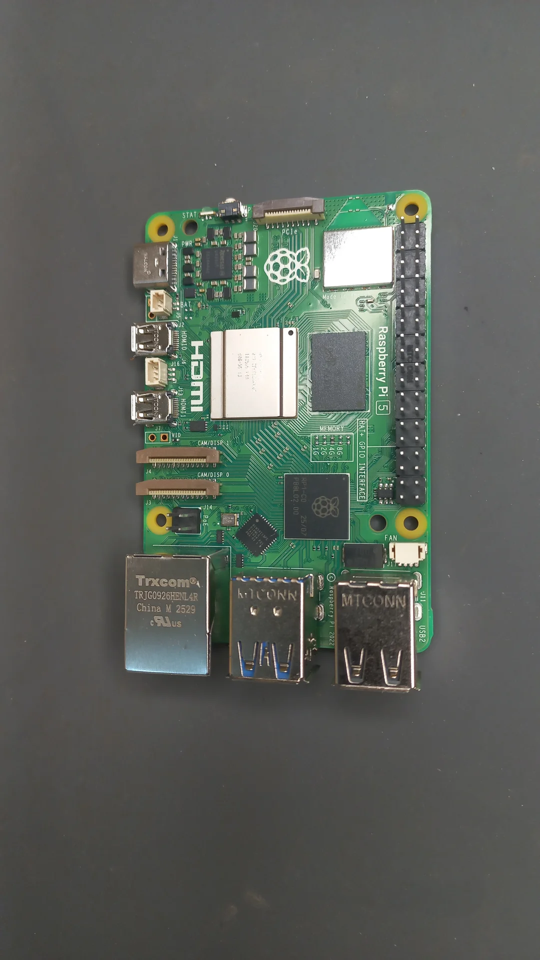
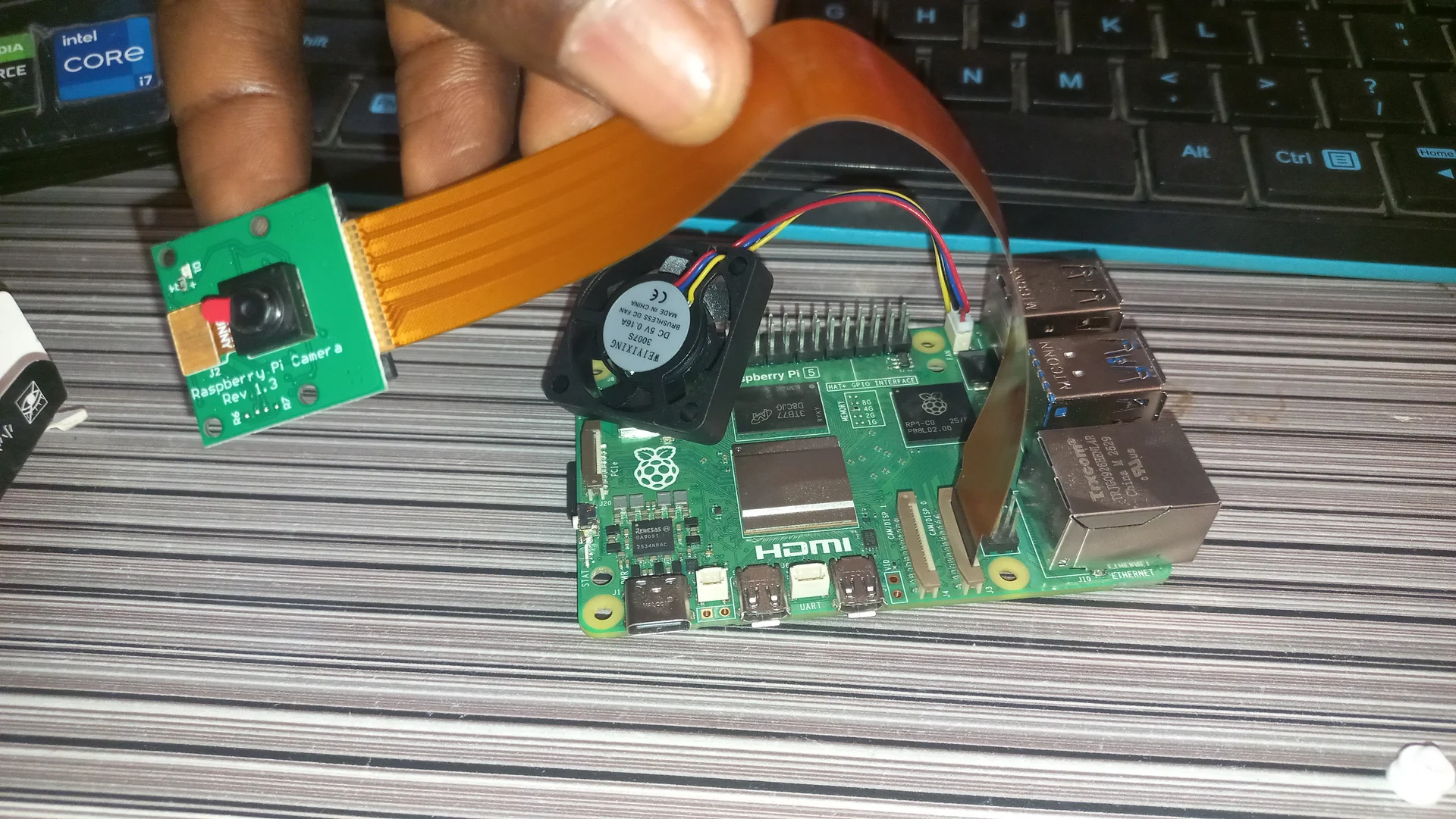
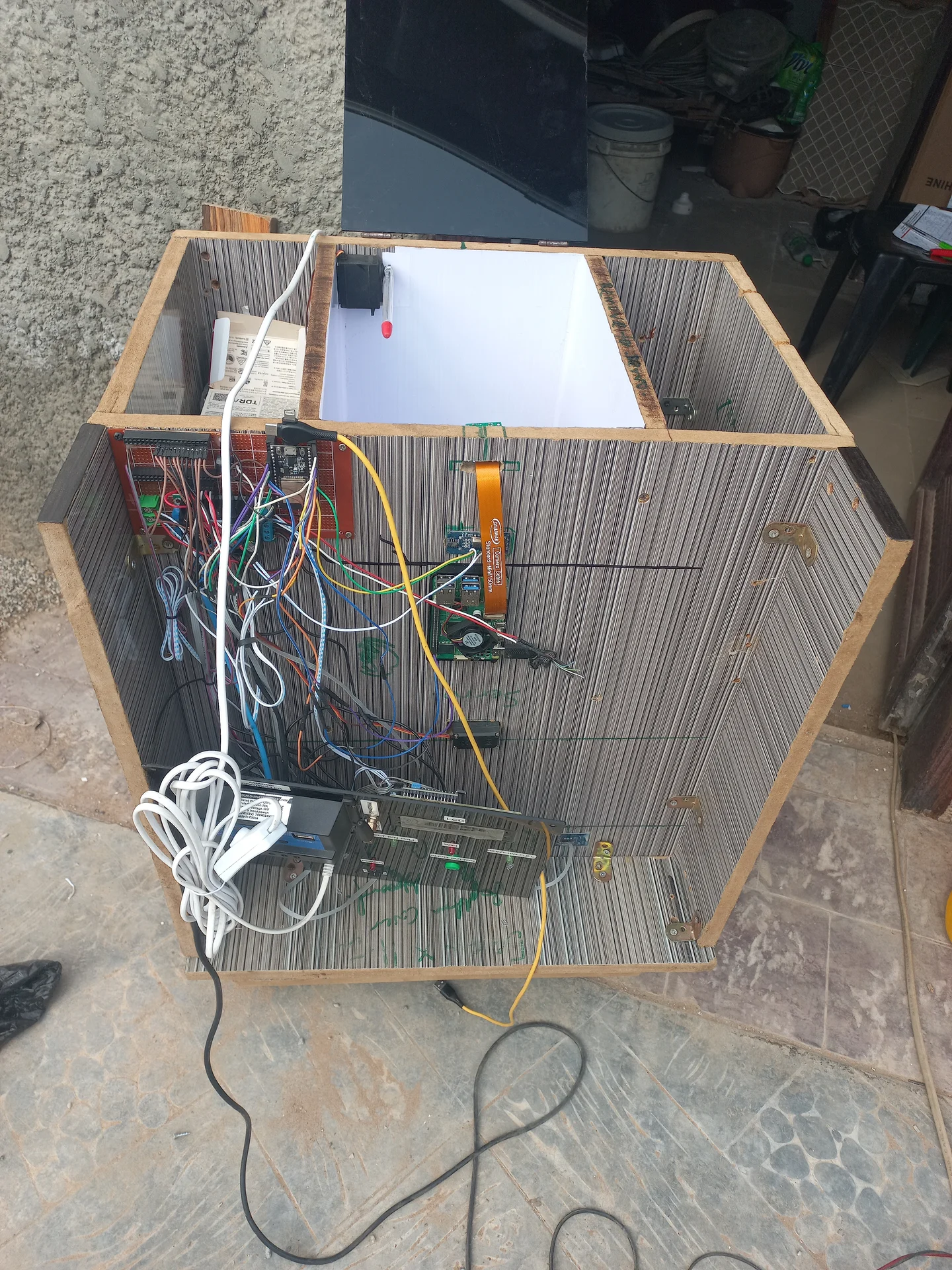
This is the AI brain of a two-processor waste sorting system. A Raspberry Pi 5 runs a custom-trained YOLO11n NCNN model that classifies waste items deposited into the bin as either Recyclable (CARDBOARD, GLASS, METAL, PAPER, PLASTIC) or Non-Recyclable (BIODEGRADABLE). The classification result is sent to an ESP32 over UART, which then physically sorts the waste using servo motors.
The Pi runs continuously in a Python state machine that waits for a SCAN trigger
from the ESP32, captures live frames with picamera2, runs NCNN inference,
votes across multiple frames over a 5-second stabilisation window, then transmits the majority
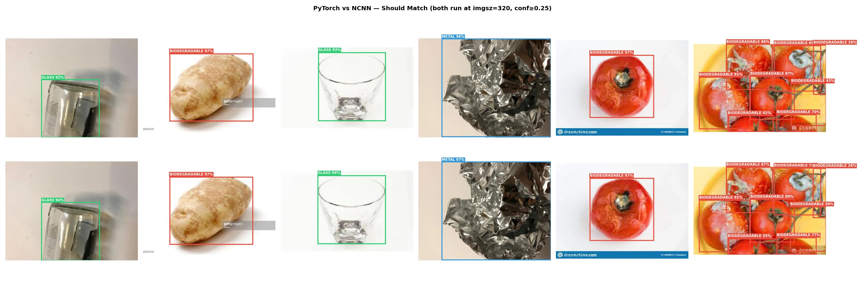
result back to the ESP32. The YOLO11n nano model was converted to NCNN for on-device ARM
optimisation, achieving 2–3× faster inference than PyTorch on the Pi 5 without any GPU.
| Component | Details |
|---|---|
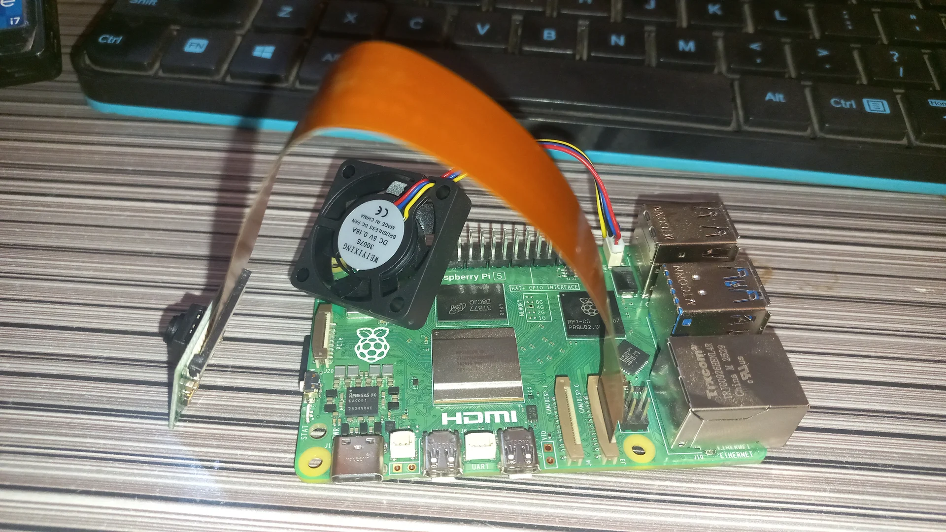
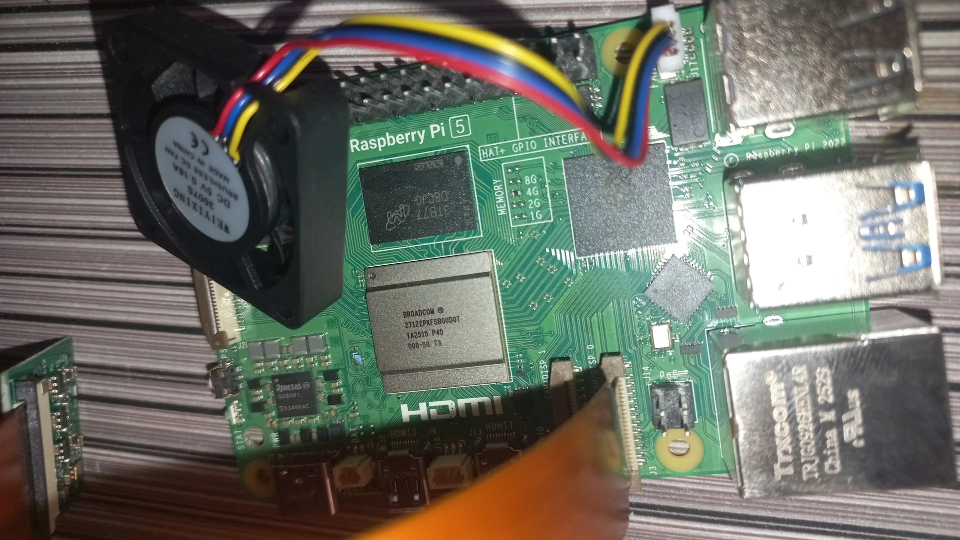
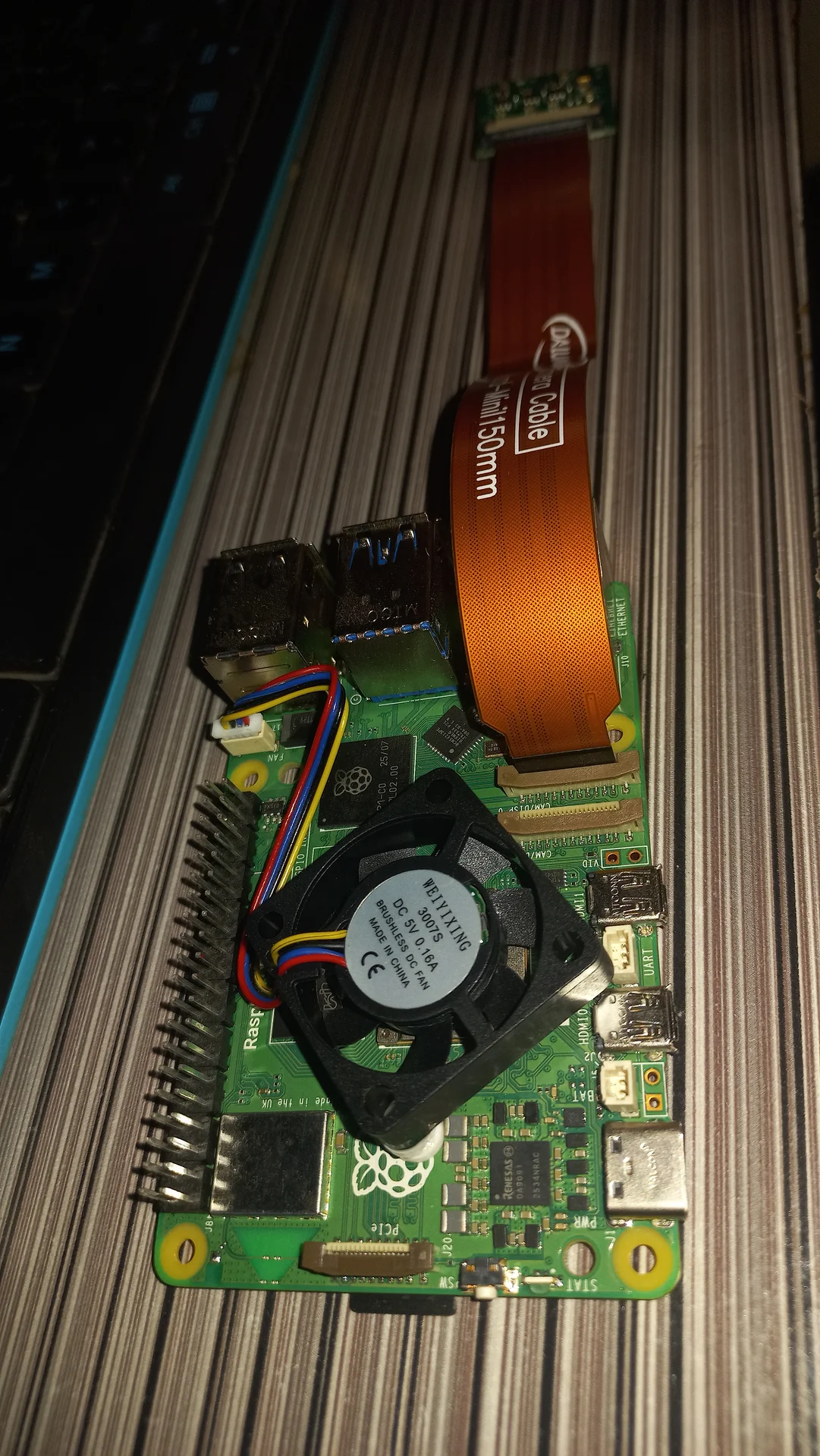
| Single-Board Computer | Raspberry Pi 5, 4 GB RAM, Broadcom BCM2712 (quad-core Cortex-A76, 2.4 GHz) |
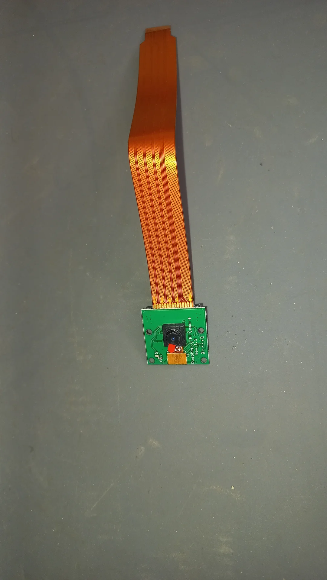
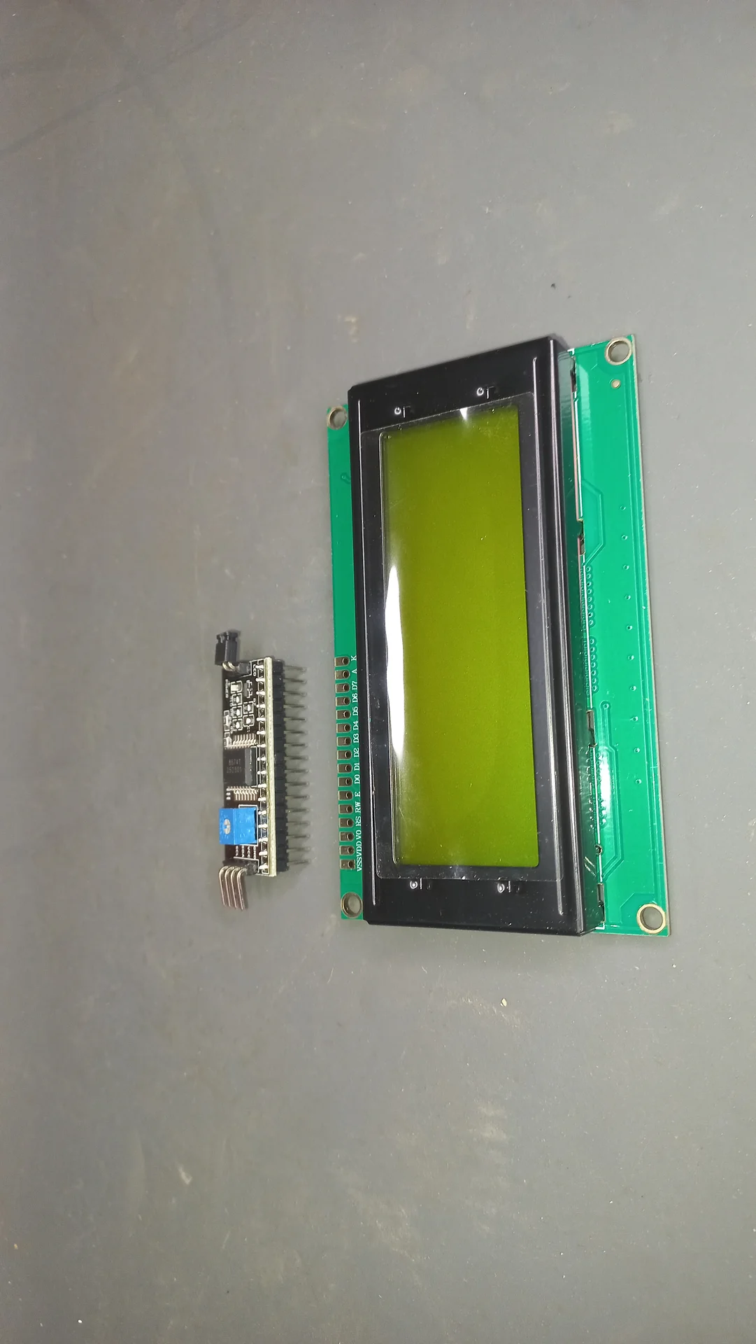
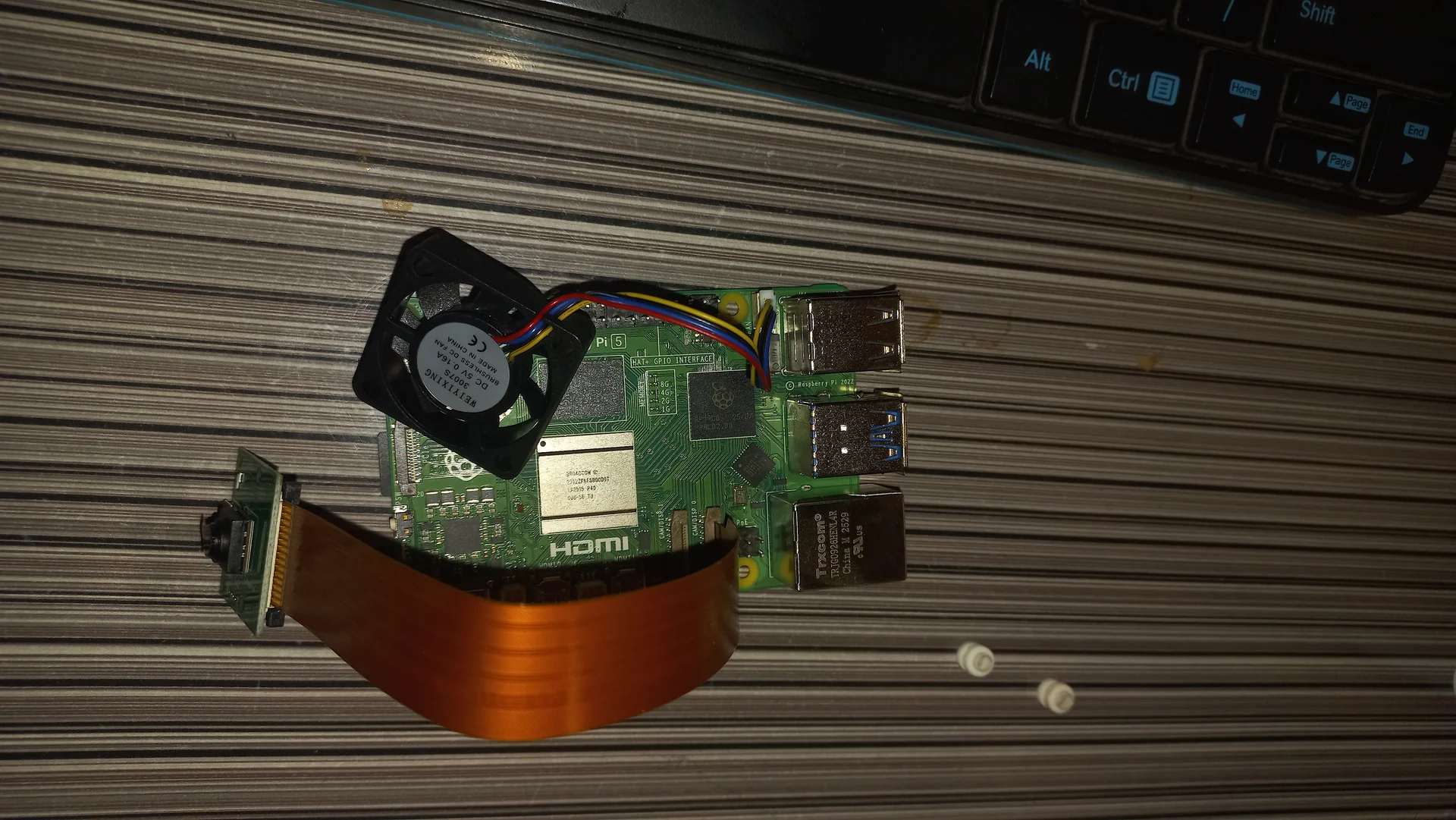
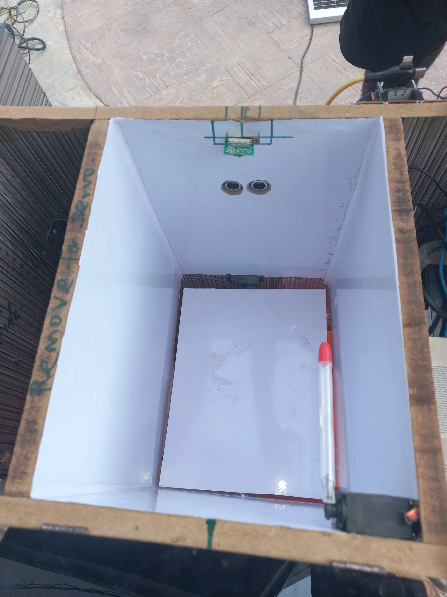
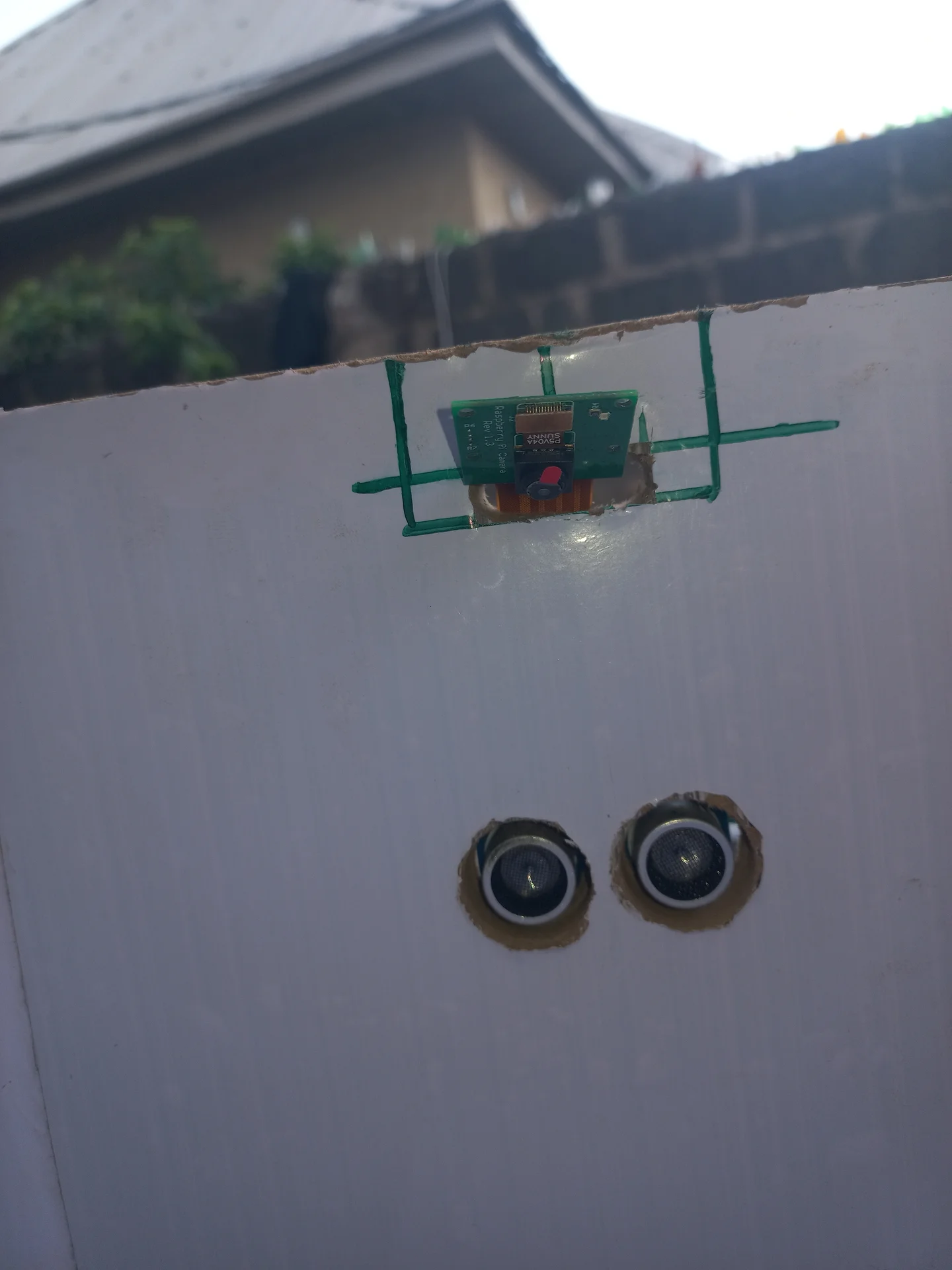
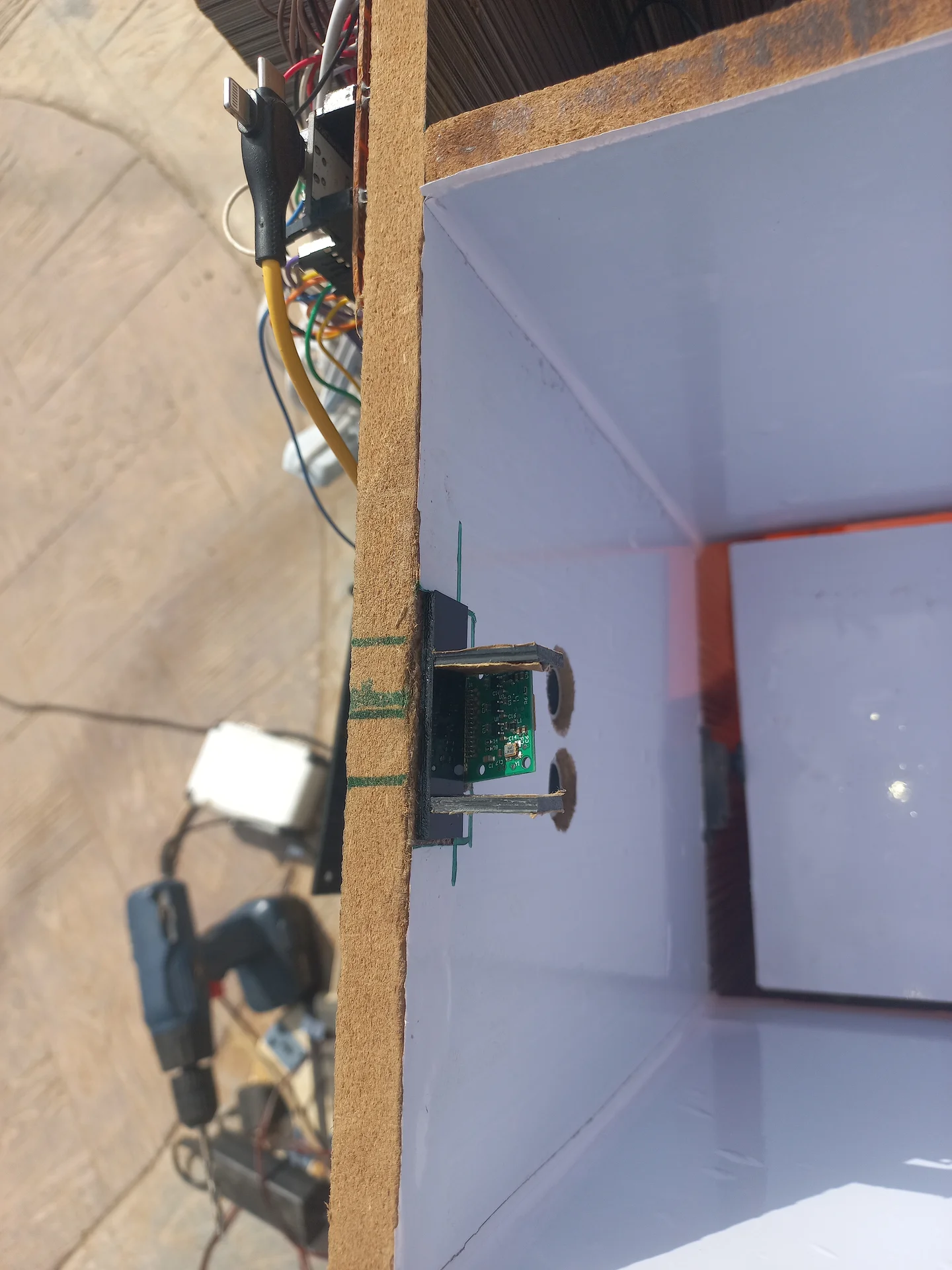
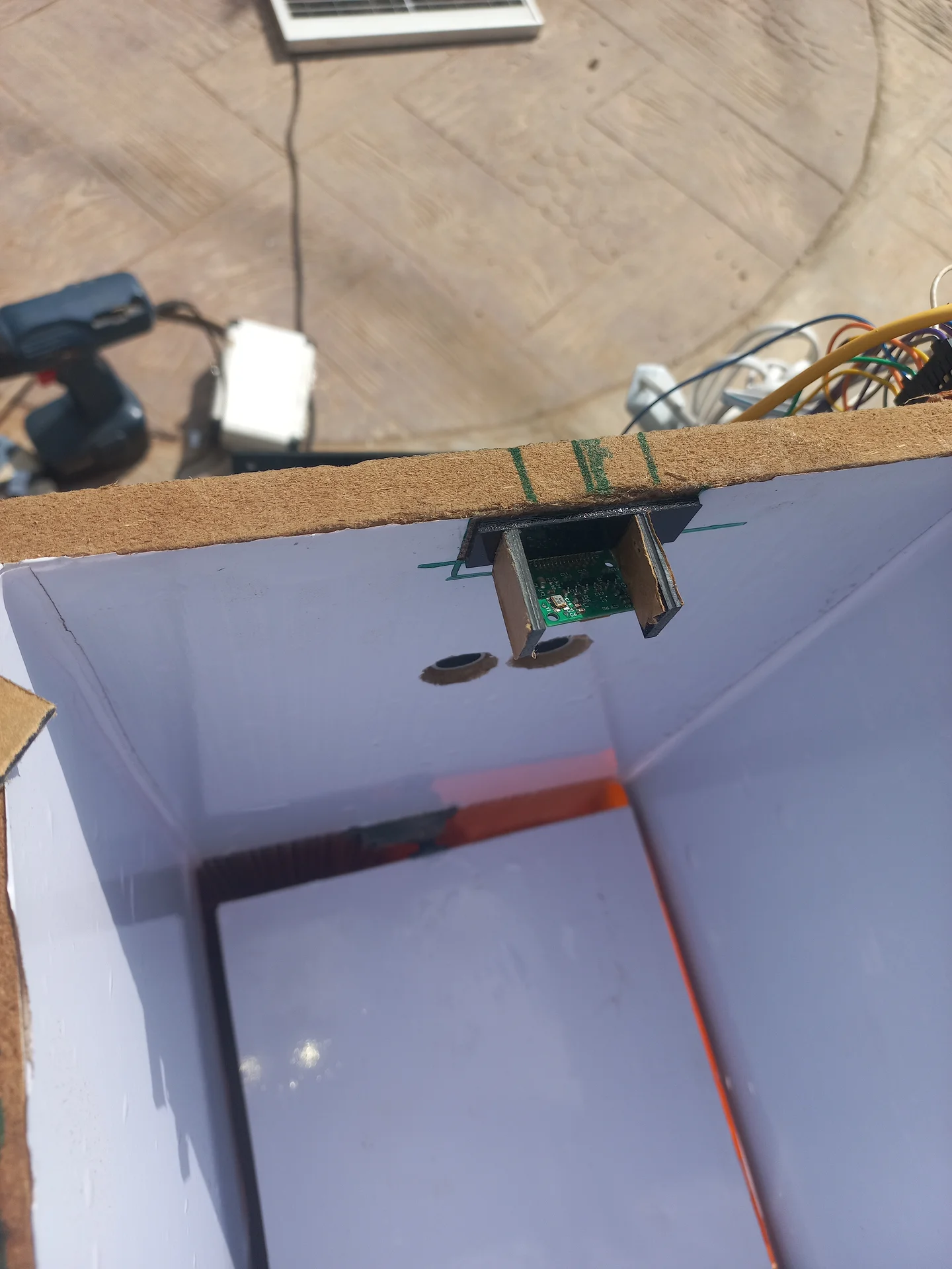
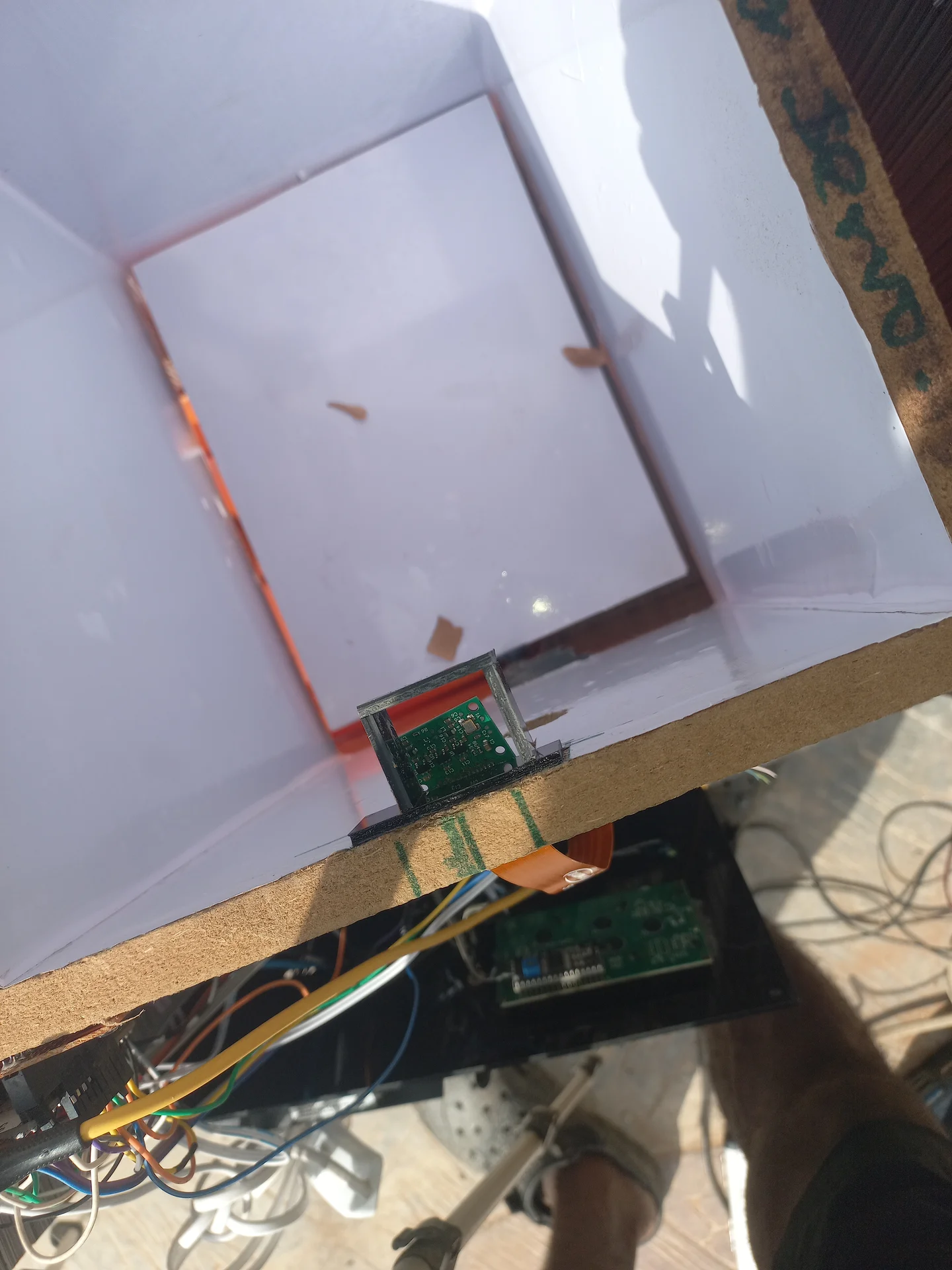
| Camera | Pi Camera Module v2, 8 MP Sony IMX219 sensor, CSI-2 interface |
| Operating System | Raspberry Pi OS Trixie (Debian 13, 64-bit) |
| UART Serial | GPIO 14 (TX) / GPIO 15 (RX), connected to ESP32 GPIO 16 / 17 at 115200 baud |
| Cooling | Active cooler recommended, NCNN inference generates sustained CPU load |
| Power | Pi 5 requires USB-C PD 5V/5A (27W) for stable operation under load |
enable_uart=1 to /boot/firmware/config.txt. Second, run
sudo raspi-config → Interface Options → Serial Port →
No (login shell) → Yes (hardware) → reboot.
The second step disables the getty process that would otherwise echo every
byte received from the ESP32 back onto the TX line, creating a UART feedback loop.dtoverlay=disable-bt. On Pi 5,
Bluetooth uses a completely separate internal path and does not share GPIO 14/15.
That overlay is only required on Pi 4 and earlier.
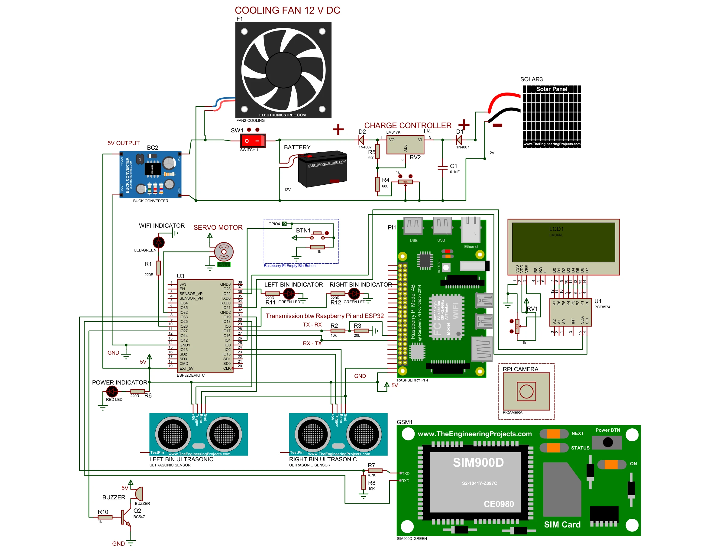
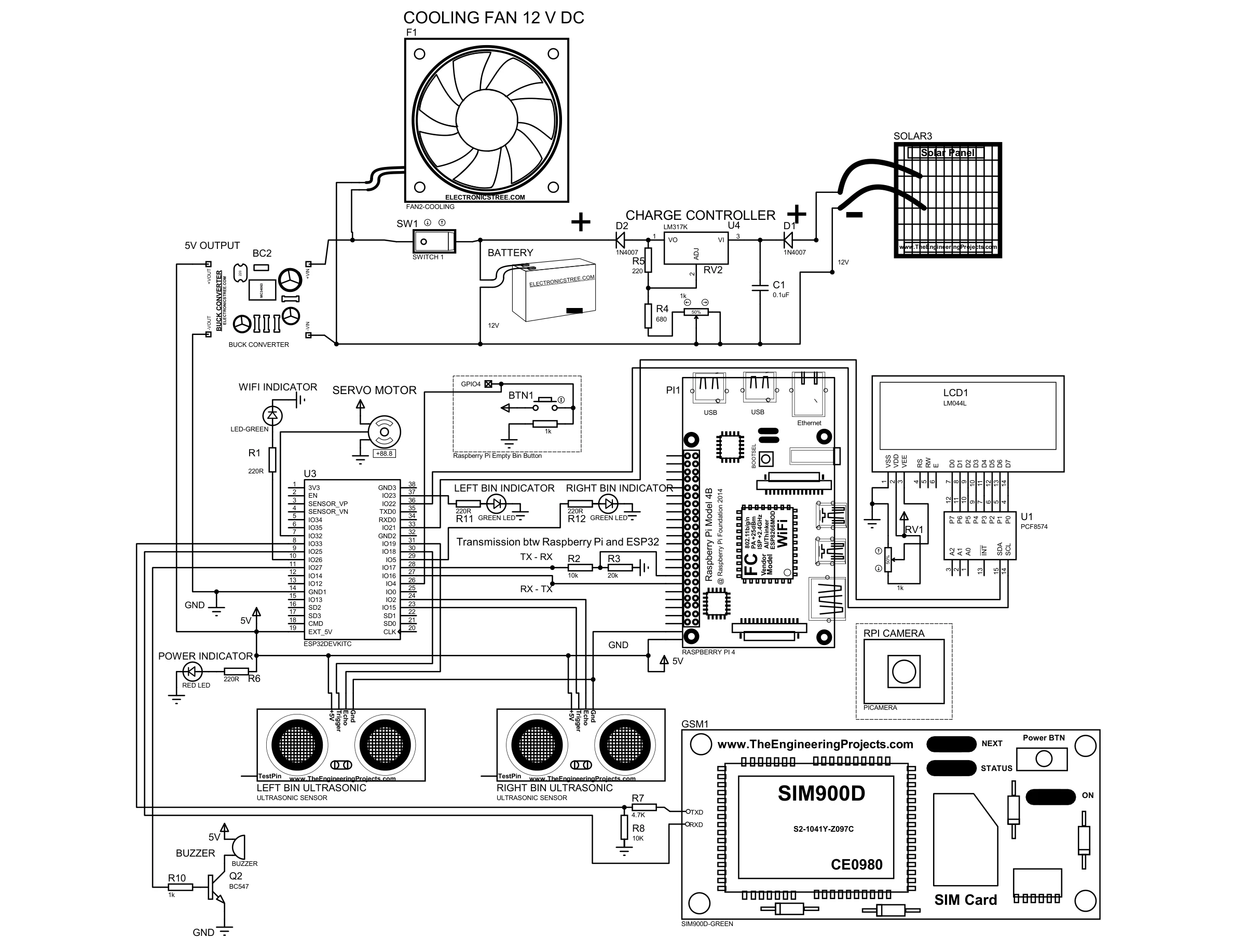
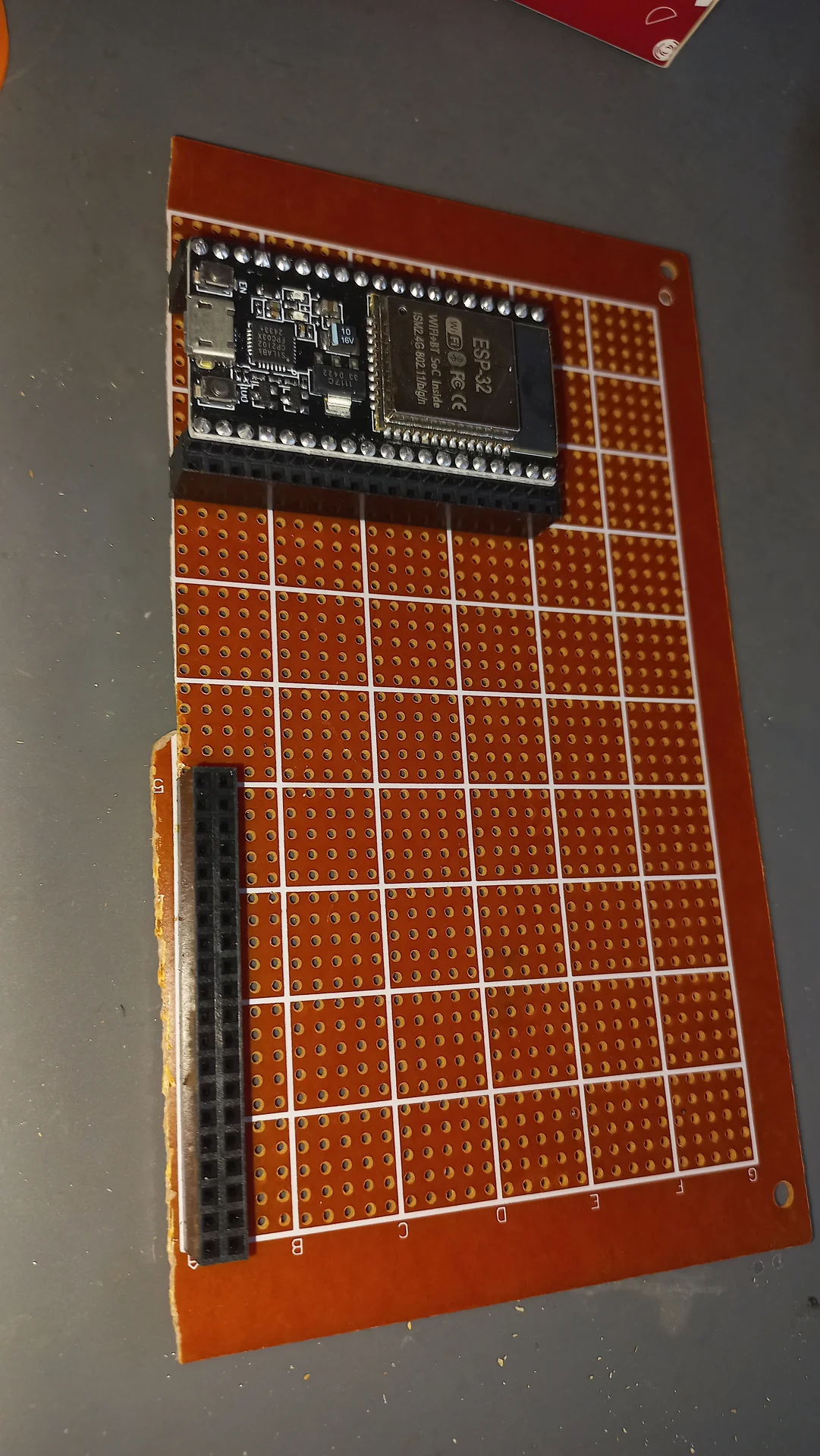
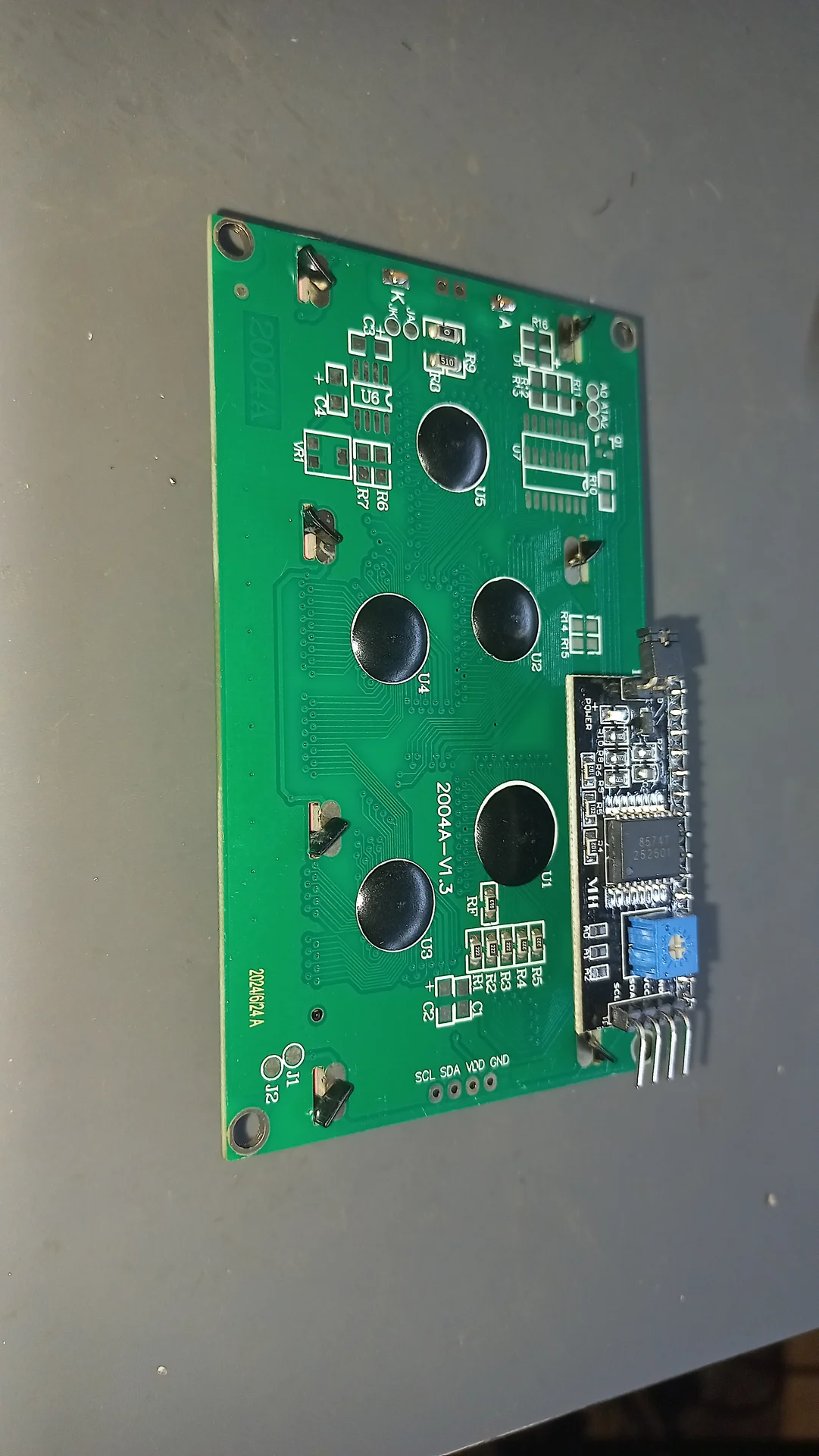
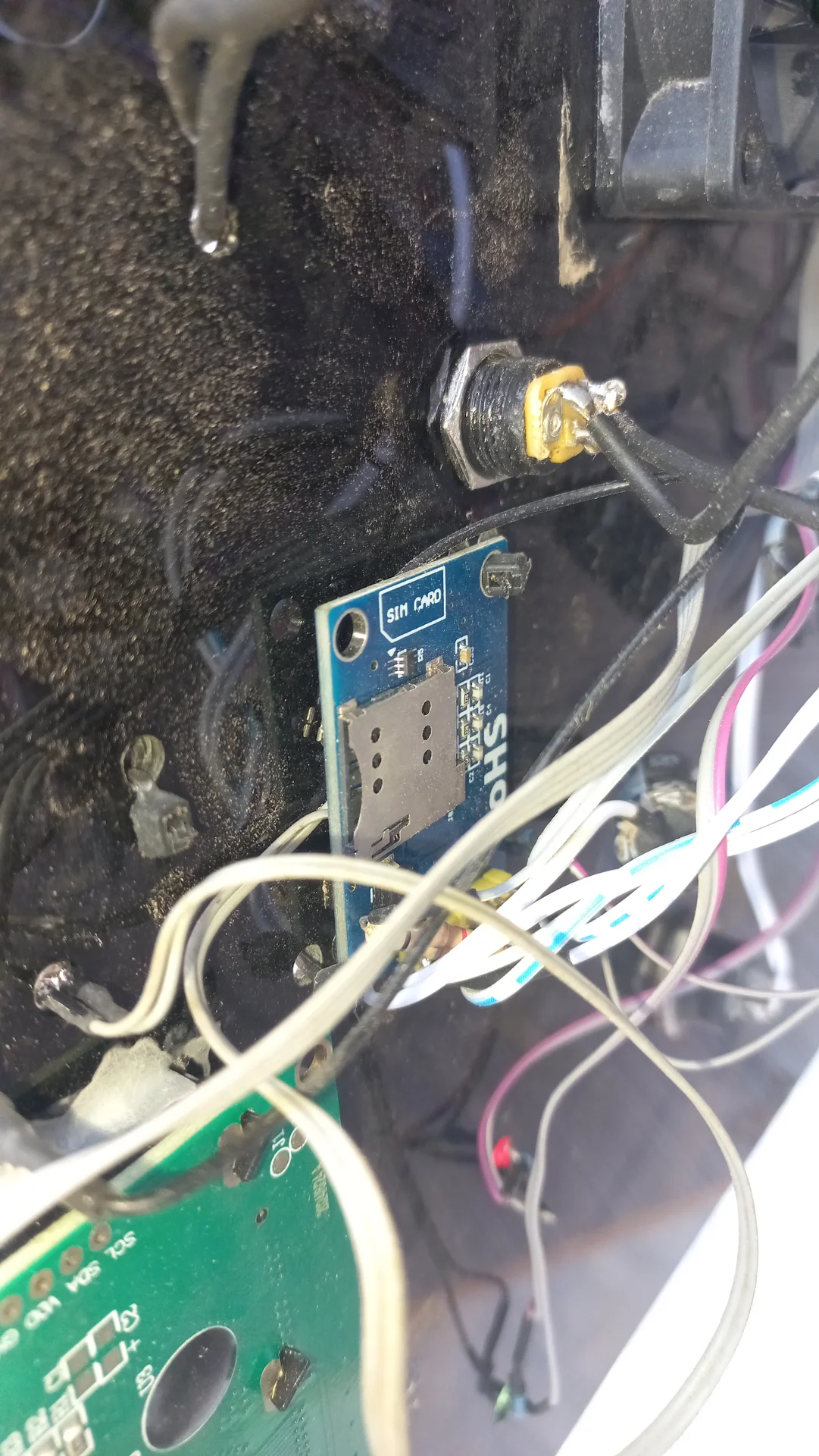
Full Proteus circuit diagram showing the complete wiring of both subsystems: the ESP32 embedded controller (sensors, servo, GSM, display, power) and the Raspberry Pi 5 inference engine (UART link, camera, power supply).
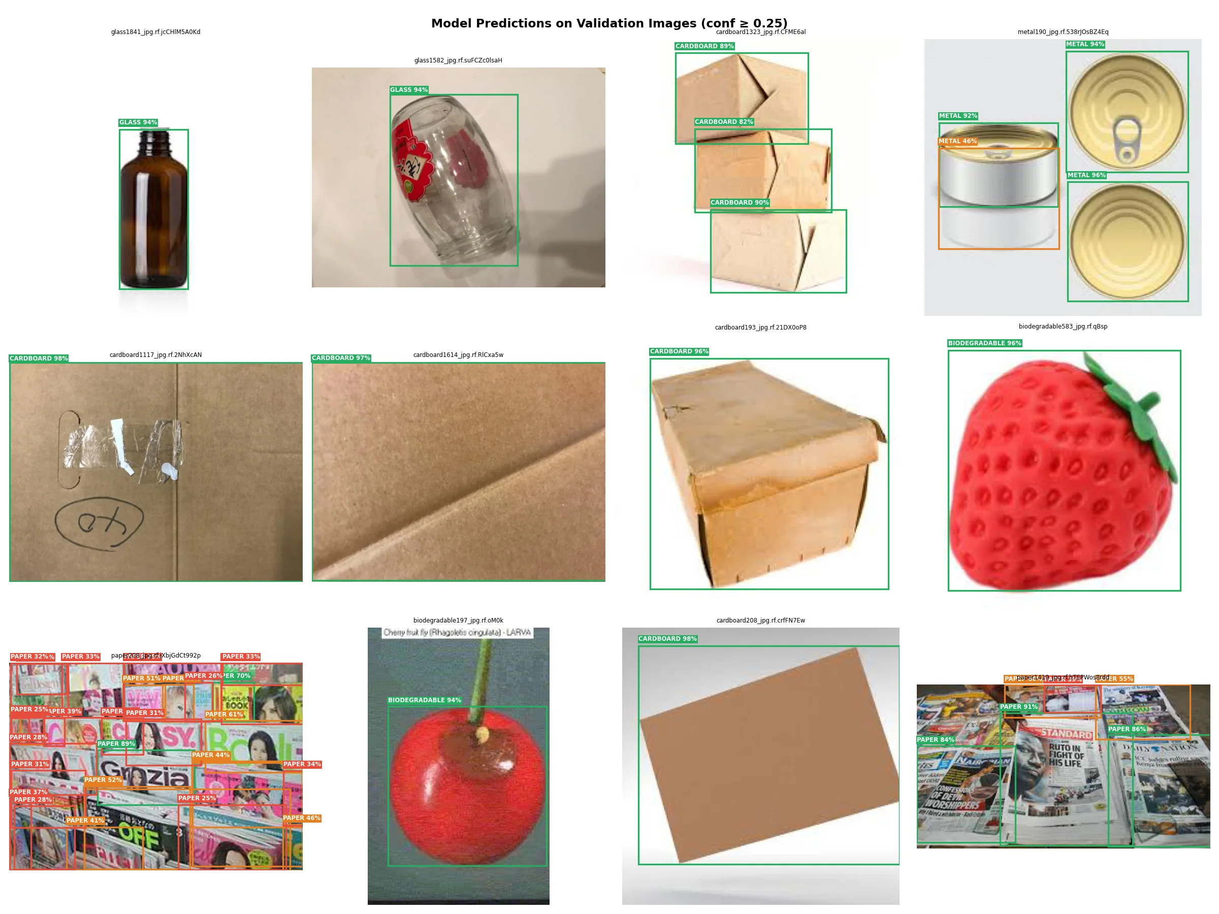
The model was trained on the GARBAGE CLASSIFICATION 3 dataset sourced from Roboflow, containing 10,464 labelled images across 6 waste categories.
| Split | Images | Share |
|---|---|---|
| Train | 7,908 | 75.6% |
| Validation | 1,776 | 17.0% |
| Test | 780 | 7.4% |
| Total | 10,464 | 100% |
Classes: BIODEGRADABLE, CARDBOARD, GLASS, METAL, PAPER, PLASTIC. Roboflow augmentations applied: horizontal flip, random crop, brightness/contrast jitter (hue/saturation were left unchanged to preserve colour as a classification signal).
Dataset split note: The Roboflow export placed all 10,464 images into
train/ with no valid/ or test/ split. The training
notebook includes a pre-training auto-split cell that moves 20% of images to
valid/ and 10% to test/ before YOLO training begins.
Without this step, validation loss cannot be computed and the best checkpoint
cannot be selected during training.
YOLO('best.pt').export(format='ncnn', imgsz=320)
via Ultralytics — do not add half=True; Pi 5 has no
FP16 hardware accelerator, so half-precision either slows inference or causes
arithmetic errors on the Cortex-A76| Training Parameter | Value |
|---|---|
| Base model | YOLO11n (nano, 2.9M parameters) |
| Framework | Ultralytics YOLO 8.3.x |
| Training environment | Google Colab, T4 GPU (16 GB VRAM) |
| Epochs | 50 (early stopping disabled) |
| Image size | 320 × 320 px |
| Batch size | 32 |
| Confidence threshold (inference) | 0.50 |
| Training duration | 1.062 hours (3,823 seconds) |
| Export format | NCNN (Tencent) for ARM CPU inference |
NCNN is a neural network inference framework developed by Tencent specifically for mobile and
embedded ARM processors. On the Raspberry Pi 5 ARM Cortex-A76 CPU, NCNN achieves
2–3× faster inference than raw PyTorch .pt due to NEON SIMD
vectorisation and Winograd convolution optimisation. OpenVINO was not used because it targets
Intel hardware. TensorRT requires Nvidia GPU. NCNN is the correct tool for this platform.
pip install ultralytics on Raspberry Pi 5 will attempt to install PyTorch with CUDA
support, which fails silently or conflicts with ARM packages. The correct install sequence for
Raspberry Pi OS (64-bit) is:sudo apt install python3-picamera2 (camera library, must use apt not pip)pip install torch --index-url https://download.pytorch.org/whl/cpu --no-deps --break-system-packagespip install ultralytics --no-deps --break-system-packagespip install ultralytics-thop --no-deps --break-system-packagespip install pyserial --break-system-packages--no-deps flag is critical on every PyTorch-related package.
Without it, pip resolves the full CUDA dependency tree and attempts to download
approximately 1.5 GB of NVIDIA libraries that do not exist for ARM and will
crash or corrupt the environment. The NCNN runtime itself does not need PyTorch;
torch is only used on Colab during the export step.
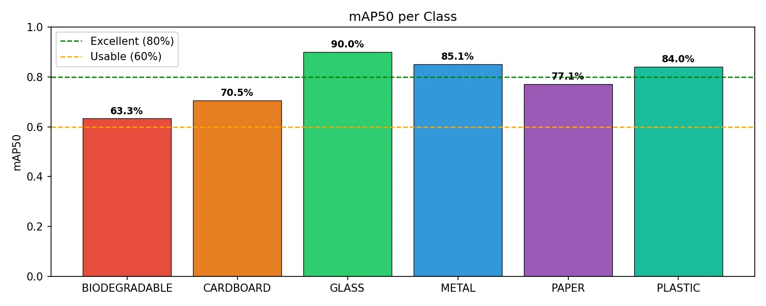
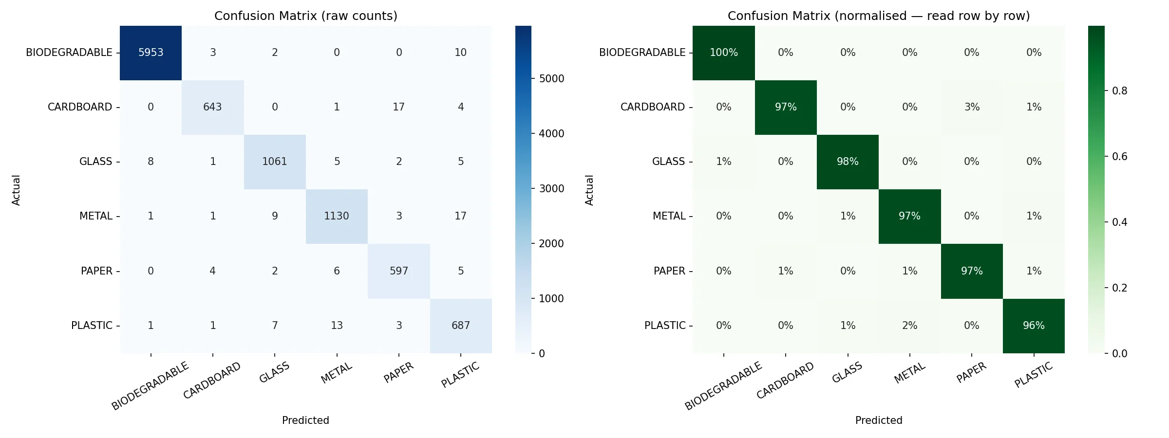
Evaluated on the held-out test set (780 images) using YOLO11n NCNN with confidence threshold 0.50 and IoU threshold 0.50 (mAP50).
The system does not need to identify the exact waste material. It only needs to decide Recyclable (R) or Non-Recyclable (N). An item correctly identified as PLASTIC (Recyclable) when the ground-truth label is GLASS (also Recyclable) is a per-class "miss" but a correct sort. In real-world testing across 4 trials, the system achieved 4/4 (100%) correct group-level sorting.
trash_sorter.py runs a four-state machine. The Pi Camera captures frames
continuously, but YOLO inference only runs in SCANNING and STABILIZING.
It is skipped entirely in WAITING and RESTING to reduce CPU temperature and power draw.
State flow: WAITING → SCANNING →
STABILIZING → RESTING → WAITING
| State | YOLO running? | Enters when | Exits when | Action on exit |
|---|---|---|---|---|
WAITING |
No | Boot complete, or RESTING timer expires | ESP32 sends SCAN\n |
Clear vote list, begin SCANNING |
SCANNING |
Yes | SCAN received from ESP32 | Any frame detects an object at ≥ 0.50 confidence | Record timestamp, start vote list → STABILIZING |
STABILIZING |
Yes | First detection in SCANNING | 5 s elapsed with object present, OR object lost mid-countdown |
5 s complete: majority vote → send R\n or N\n → RESTING.Object lost: clear votes → back to SCANNING (no signal sent). |
RESTING |
No | Result transmitted at end of STABILIZING | 5 s cooldown elapses | Return to WAITING; next cycle waits for next SCAN |
R or N has been
transmitted, the ESP32 immediately starts servo actuation. The Pi's 5-second rest
window exists solely to prevent a second SCAN from being accepted while
the physical sort is still in progress. The result is transmitted the instant the
5-second majority-vote window closes — that is the final moment of STABILIZING,
not the start of RESTING.
If the item slides out of frame or tips over during the STABILIZING countdown, the state resets to SCANNING with the vote list cleared and no signal sent. The 5-second window restarts cleanly the moment the object is re-detected above the confidence threshold. This prevents any partial or ambiguous vote from producing a sort result.
The 5-second STABILIZE window (increased from 2.5 s during development) was confirmed necessary after testing revealed that the first 1–2 seconds of detection can be dominated by a side-angle view of the item as it drops and settles, which skews the vote toward the wrong class. The longer window gives the item time to come to rest in a face-on orientation before the majority is computed.
The full source is available on GitHub. These are the most architecturally significant sections of
trash_sorter.py.
from ultralytics import YOLO
from picamera2 import Picamera2
import numpy as np

# Load NCNN model (converted from best.pt on Colab)
model = YOLO("best_ncnn_model/", task="detect")

# picamera2 setup — fixed resolution for NCNN imgsz=320
picam2 = Picamera2()
config = picam2.create_preview_configuration(
    main={"size": (640, 480), "format": "RGB888"}
)
picam2.configure(config)
picam2.start()

def classify_frame() -> str | None:
    """
    Capture one frame and return the highest-confidence class name,
    or None if no detection exceeds the confidence threshold (0.50).
    """
    frame = picam2.capture_array()          # BGR numpy array
    results = model(frame, conf=0.50, verbose=False)

    best_cls  = None
    best_conf = 0.0
    for box in results[0].boxes:
        cls_id = int(box.cls[0])
        conf   = float(box.conf[0])
        if conf > best_conf:
            best_conf = conf
            best_cls  = model.names[cls_id]  # e.g. "GLASS"

return best_cls # None if nothing detected above thresholdThe condensed logic below shows how SCANNING and STABILIZING are separate states, and where the UART signal is actually transmitted.
import serial, time

ser = serial.Serial("/dev/ttyAMA0", baudrate=115200, timeout=0)

STABILIZE_SEC = 5.0    # hold the item for this long before sending result
REST_SECONDS  = 5      # post-sort cooldown; no new SCAN accepted
CONF_THRESH   = 0.50   # frames below this confidence do not count

RECYCLABLE = {"CARDBOARD", "GLASS", "METAL", "PAPER", "PLASTIC"}

STATE_WAITING     = "WAITING"
STATE_SCANNING    = "SCANNING"
STATE_STABILIZING = "STABILIZING"
STATE_RESTING     = "RESTING"

state        = STATE_WAITING
stable_start = None
stable_votes = []
rest_end     = None

while True:
    # Non-blocking UART read — checked every frame regardless of state
    incoming = ""
    if ser.in_waiting > 0:
        incoming = ser.read(ser.in_waiting).decode("utf-8", errors="ignore").strip()

    frame_bgr = picam2.capture_array()  # Pi Camera v2 delivers BGR bytes

    # ── WAITING: YOLO is OFF; only listening for SCAN ────────────────────
    if state == STATE_WAITING:
        if incoming == "SCAN":
            state = STATE_SCANNING
        # frame captured but NOT passed to model

    else:
        # ── Run YOLO inference (SCANNING and STABILIZING only) ────────────
        results = model(frame_bgr, imgsz=320, conf=CONF_THRESH, verbose=False)
        detected_label = None
        for r in results:
            for box in r.boxes:
                detected_label = model.names[int(box.cls[0])]

        # ── SCANNING: wait for the first detection ────────────────────────
        if state == STATE_SCANNING:
            if detected_label:
                state        = STATE_STABILIZING
                stable_start = time.time()
                stable_votes = [detected_label]

        # ── STABILIZING: accumulate votes for 5 s ────────────────────────
        elif state == STATE_STABILIZING:
            if detected_label:
                stable_votes.append(detected_label)
                elapsed = time.time() - stable_start
                if elapsed >= STABILIZE_SEC:
                    # Majority vote → send signal → RESTING
                    final  = max(set(stable_votes), key=stable_votes.count)
                    signal = b"R\n" if final in RECYCLABLE else b"N\n"
                    ser.write(signal)          # signal sent here, end of STABILIZING
                    ser.flush()
                    state    = STATE_RESTING
                    rest_end = time.time() + REST_SECONDS
                    stable_votes = []
            else:
                # Object lost before countdown finished — no signal sent
                state        = STATE_SCANNING
                stable_votes = []
                stable_start = None

        # ── RESTING: cooldown only; no classification, no signals ─────────
        elif state == STATE_RESTING:
            if time.time() >= rest_end:
                state    = STATE_WAITING
rest_end = NoneThe Pi script starts automatically on boot via a systemd unit. The service uses
Restart=on-failure so the detector restarts after unexpected crashes
but does not loop endlessly after a deliberate stop.
cv2.imshow() will immediately raise a
cv2.error: (-215) !_src.empty() and crash the service.
The variable SHOW_PREVIEW = False must be set in
trash_sorter.py before deploying the systemd service.
Preview mode is only useful during interactive development sessions.
# /etc/systemd/system/trash-sorter.service

[Unit]
Description=Trash Sorter AI Detection System
After=multi-user.target

[Service]
Type=simple
User=adegoke
WorkingDirectory=/home/adegoke/trash_project
ExecStart=/usr/bin/python3 /home/adegoke/trash_project/trash_sorter.py
Restart=on-failure
RestartSec=5
StandardOutput=journal
StandardError=journal

[Install]
WantedBy=multi-user.target

# sudo systemctl daemon-reload
# sudo systemctl enable trash-sorter.service
# sudo systemctl start  trash-sorter.service
# sudo journalctl -fu trash-sorter.service (live logs)READY handshake within 20 seconds
of Pi power-on, and waste sorting proceeds normally.
Ten real hardware and software engineering challenges were solved during development. Each solution directly shaped the final system architecture.
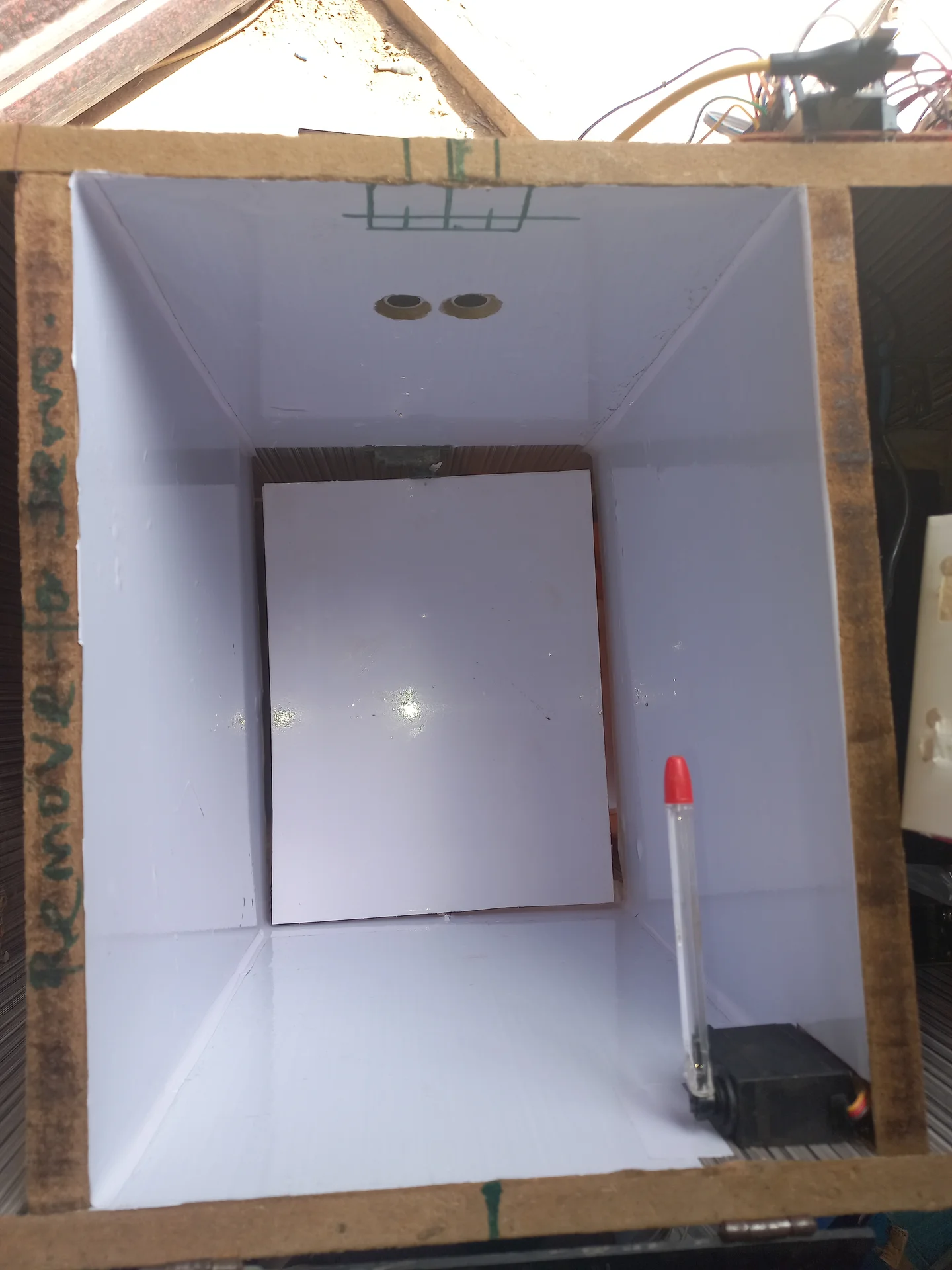
A piece of waste falling through the air momentarily reflects sound waves, making the bin appear full before it lands. The fix was an Obstruction Verification Delay: the ESP32 sets a flag and starts a millis() timer. Only if the reading stays below FULL_THRESHOLD continuously for 4.5 seconds is the bin officially locked. Transient reflections clear themselves.
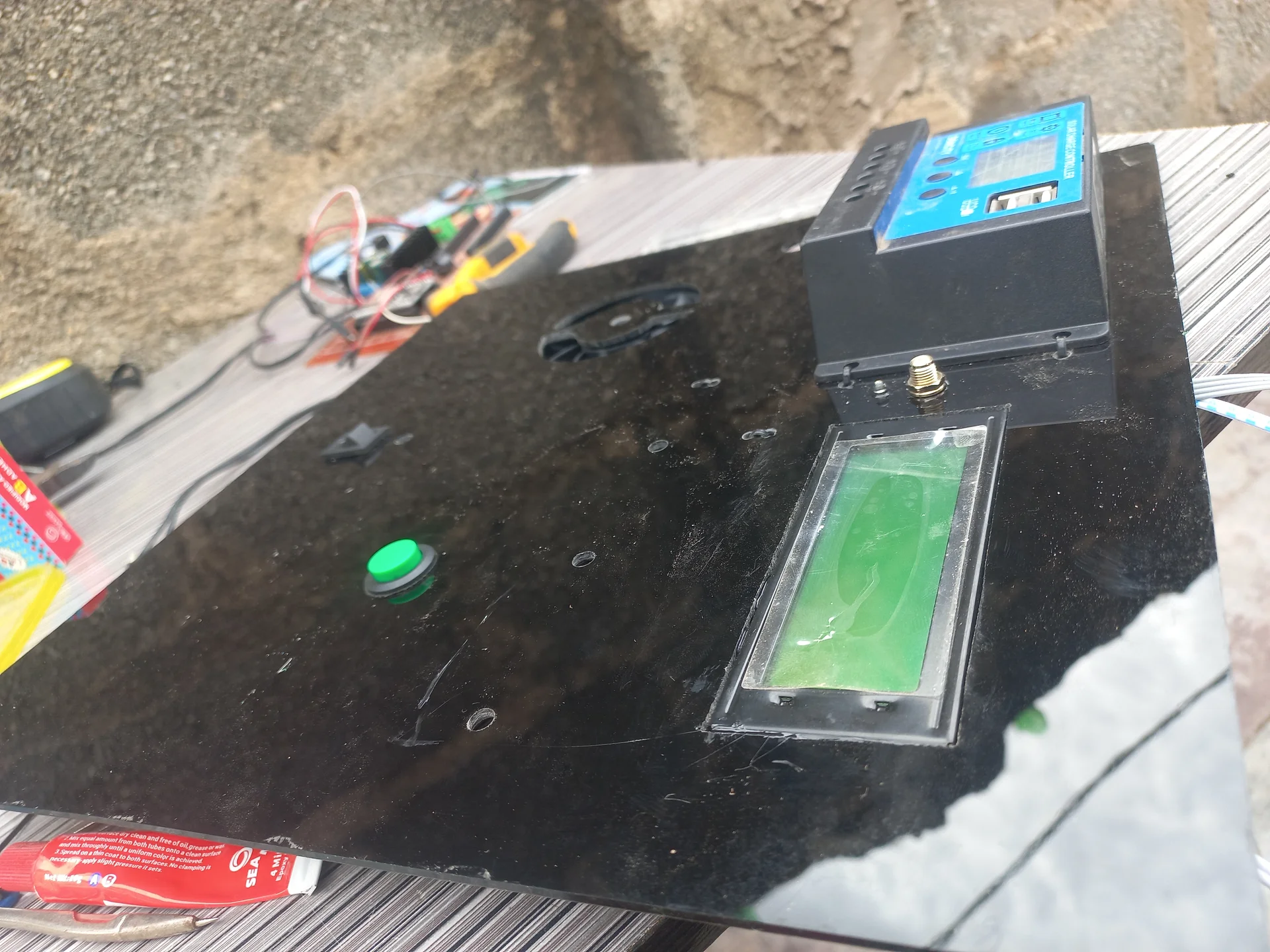
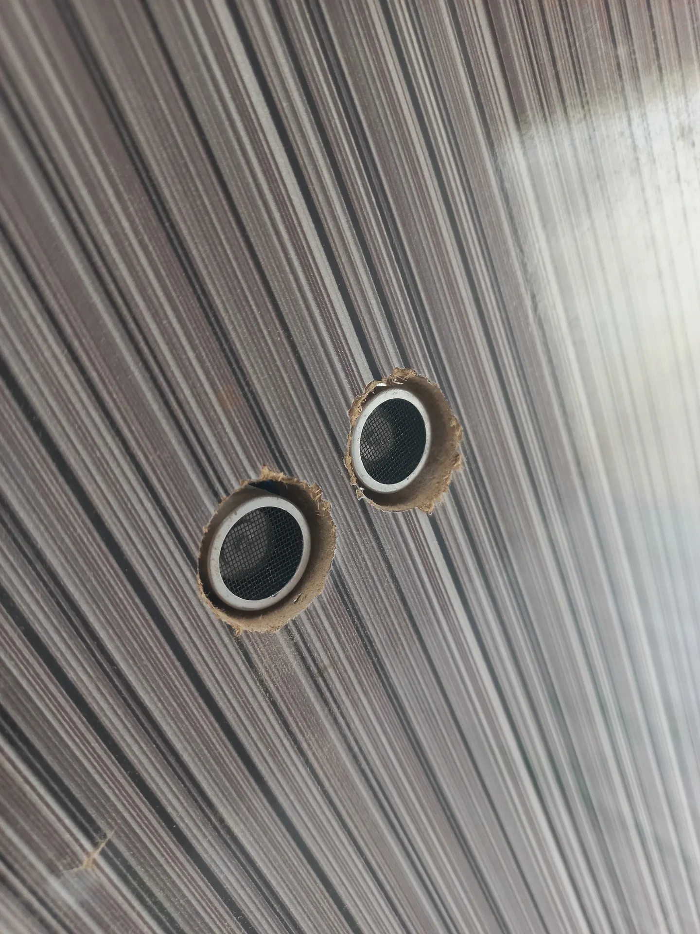
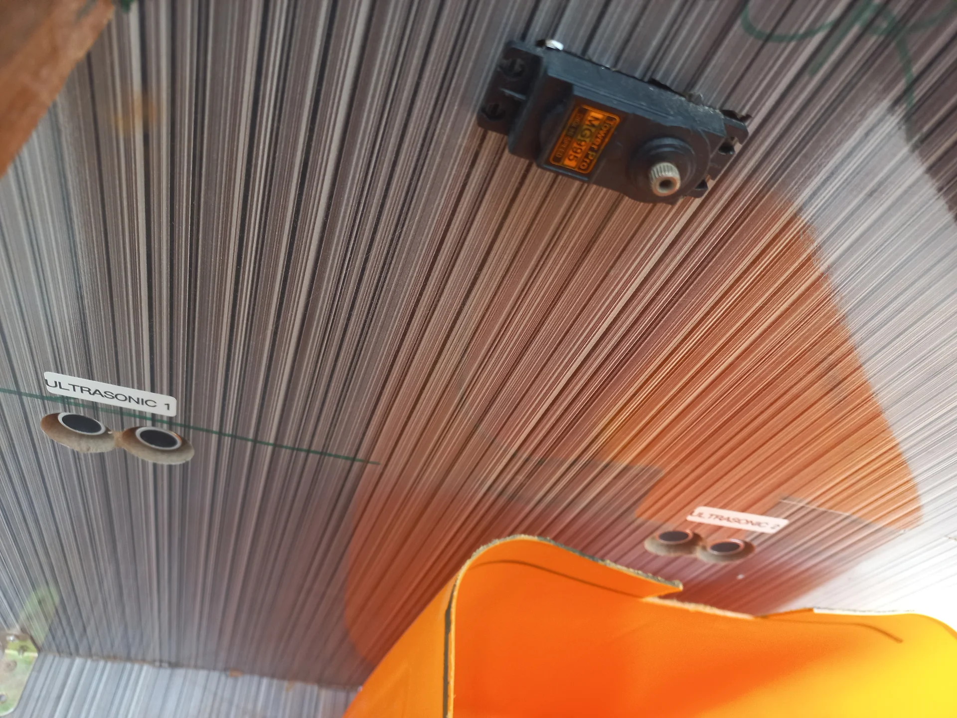
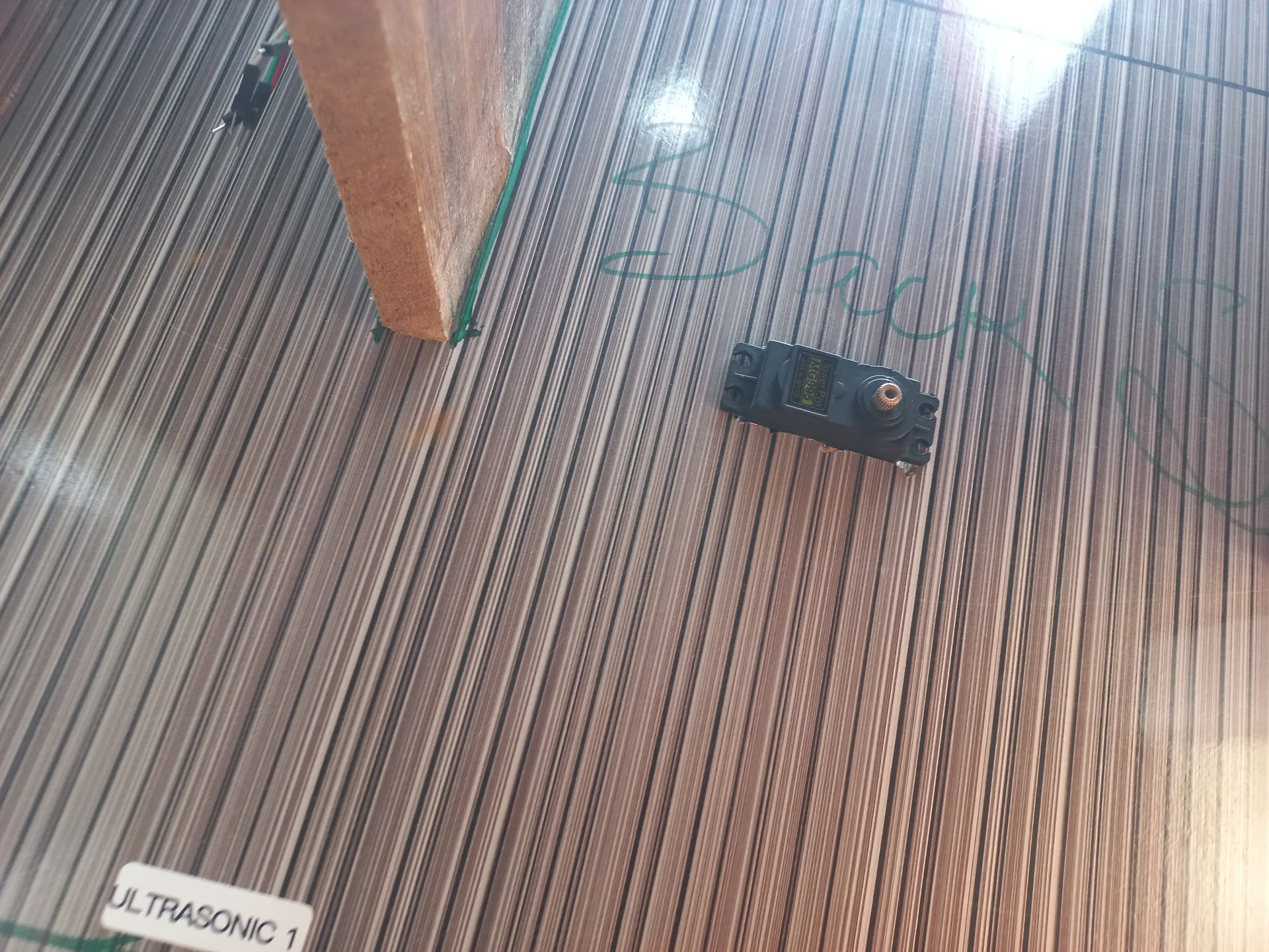
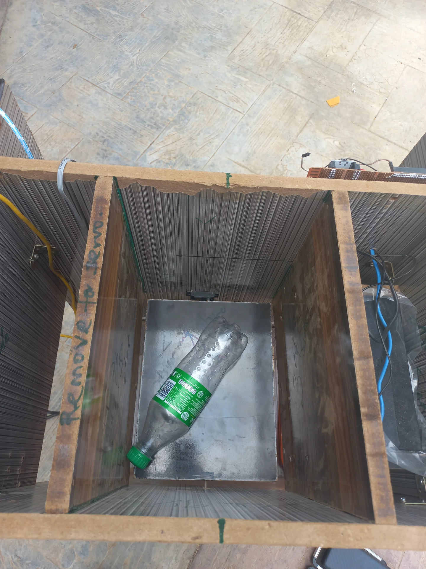
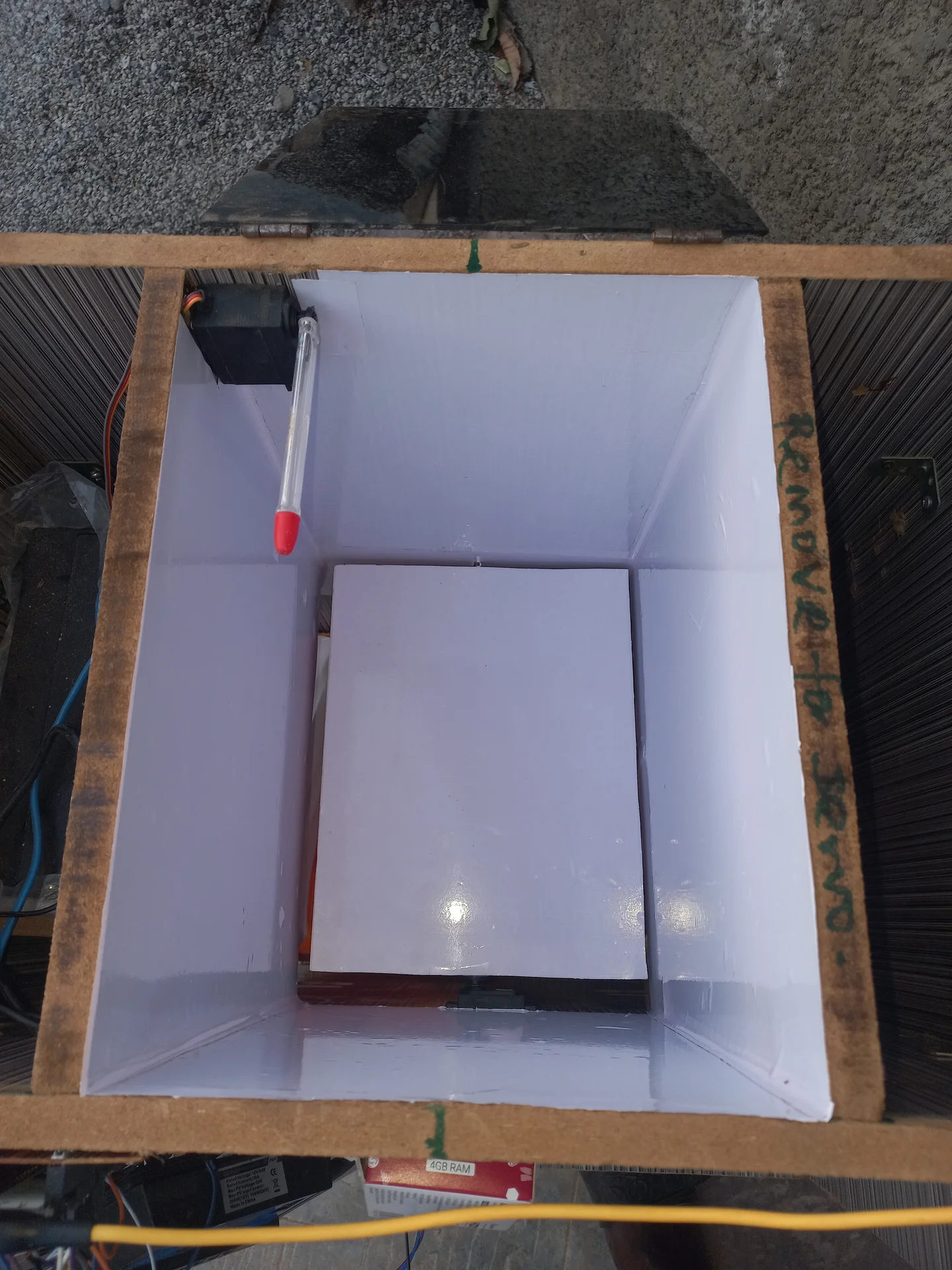
Downward-pointing sensors produce inaccurate fill levels because waste piles unevenly (a bottle standing upright in the centre triggers a false "full" while 90% of the space is empty). Mounting sensors horizontally across the brim turns them into a tripwire: any reading below 16 cm means the horizontal beam is physically blocked, which only happens when the bin is actually full.
At 30 fps, the Pi would send 30 classification signals per second, flooding the ESP32 serial buffer and causing the servo to repeat its sweep until the system crashed. The solution was a Handshake & Cooldown Protocol: after sending one R\n or N\n, the Pi enters a 5-second STATE_RESTING. On the ESP32 side, immediately after executing the mechanical sweep, a buffer flush loop reads and discards any stale serial bytes before accepting the next command.
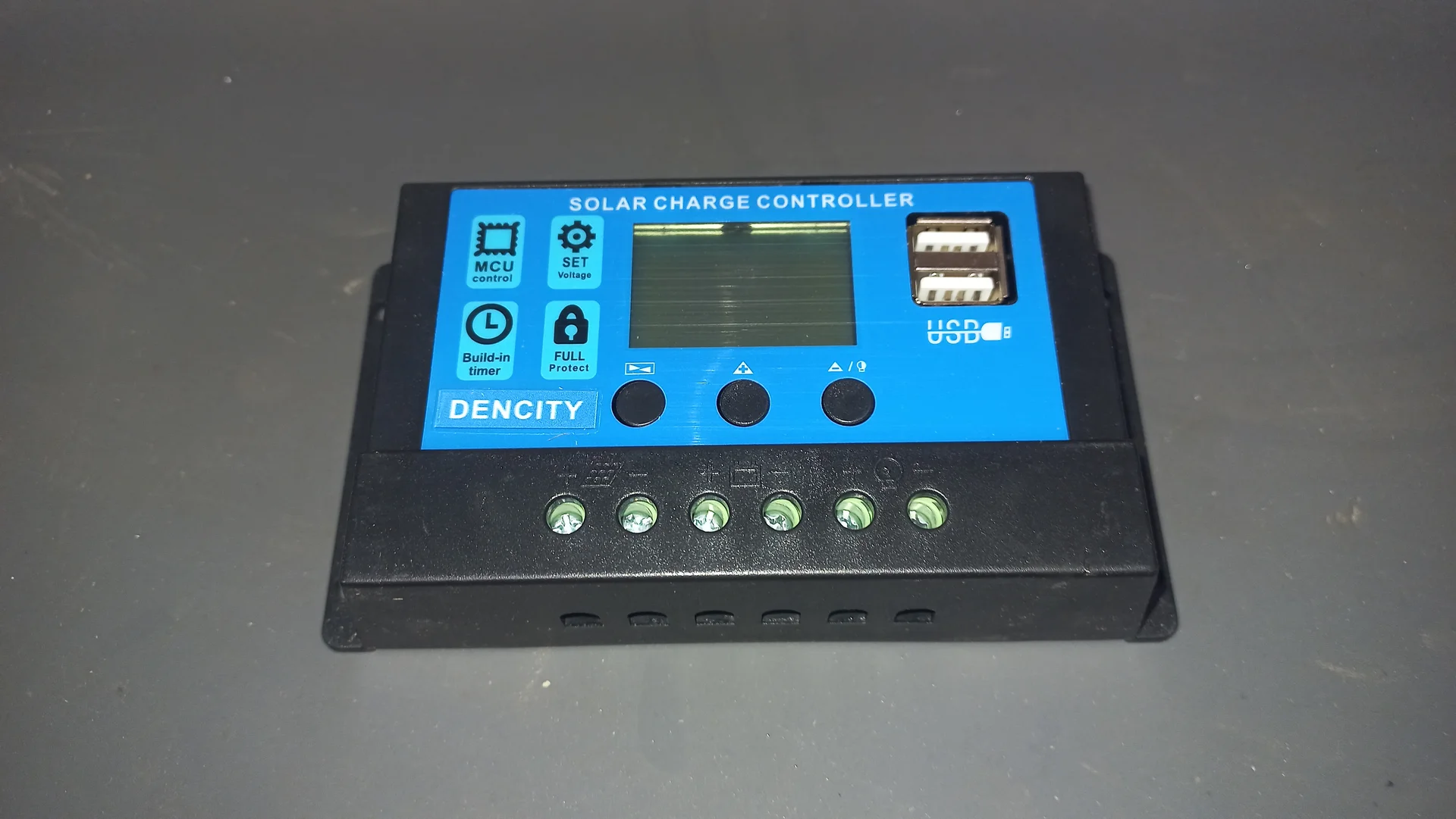
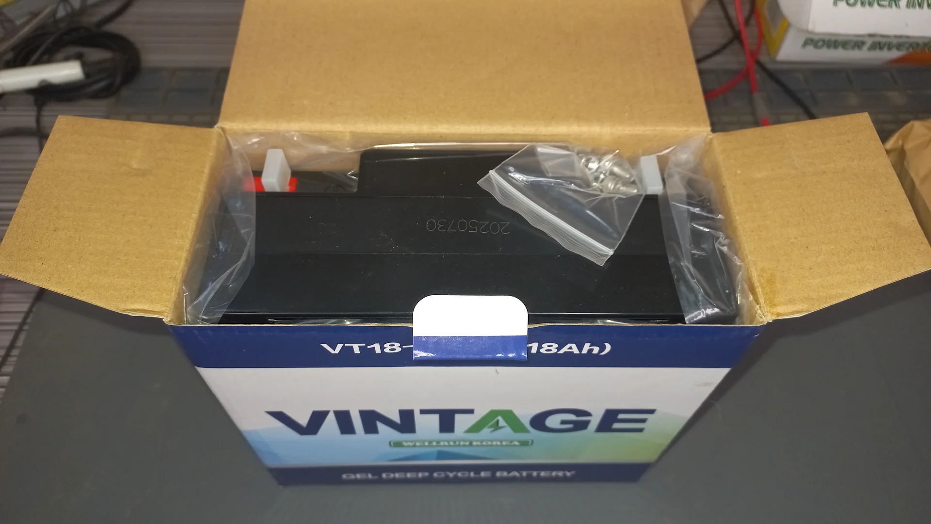
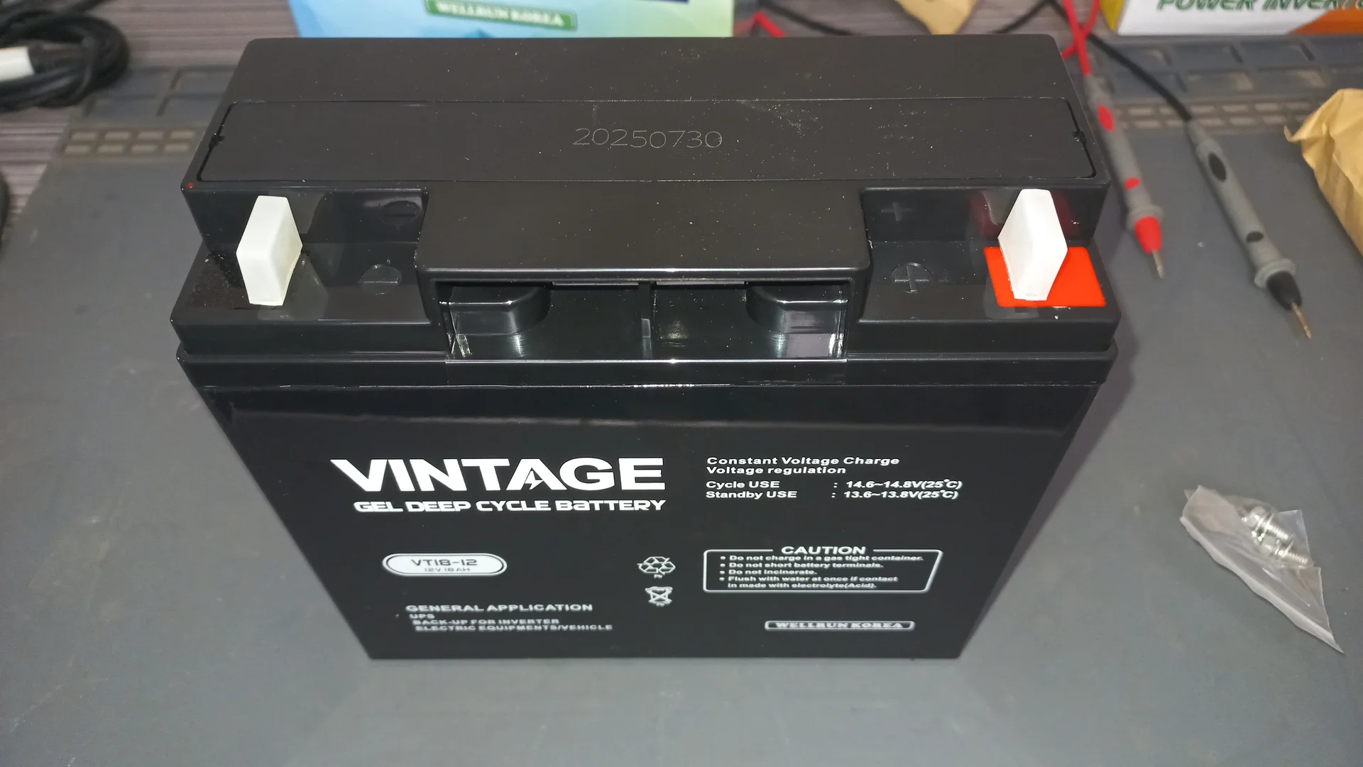
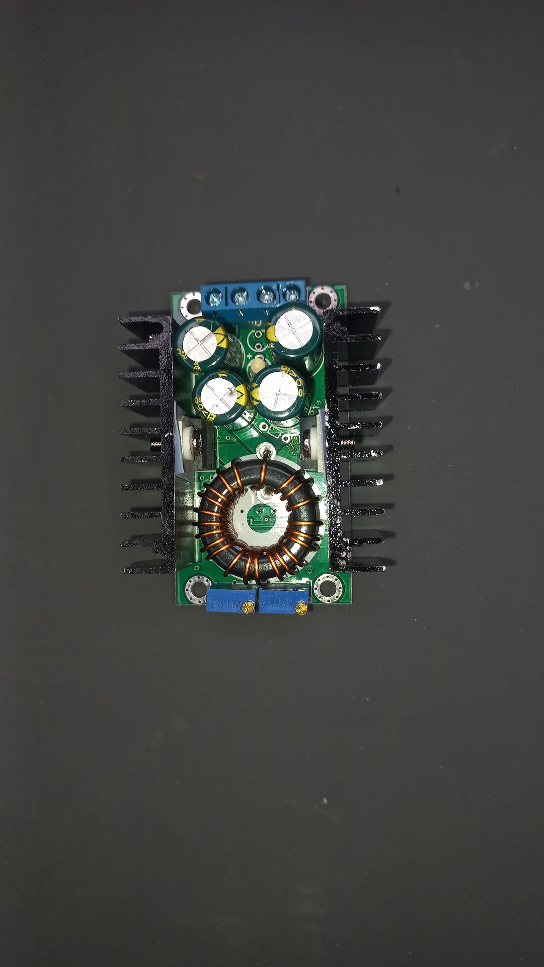
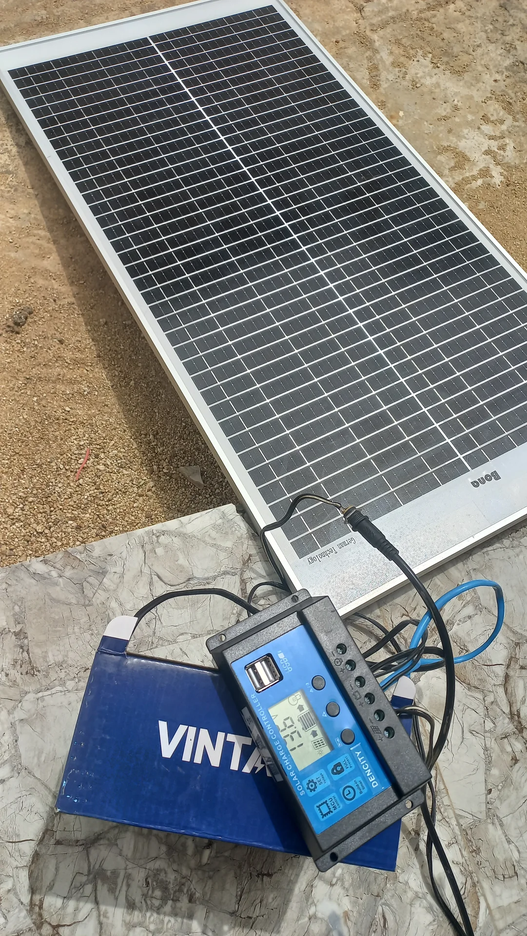
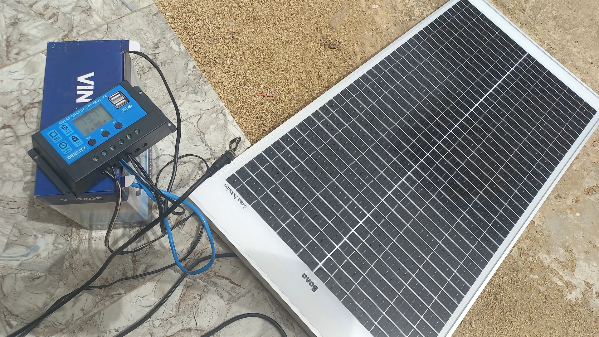
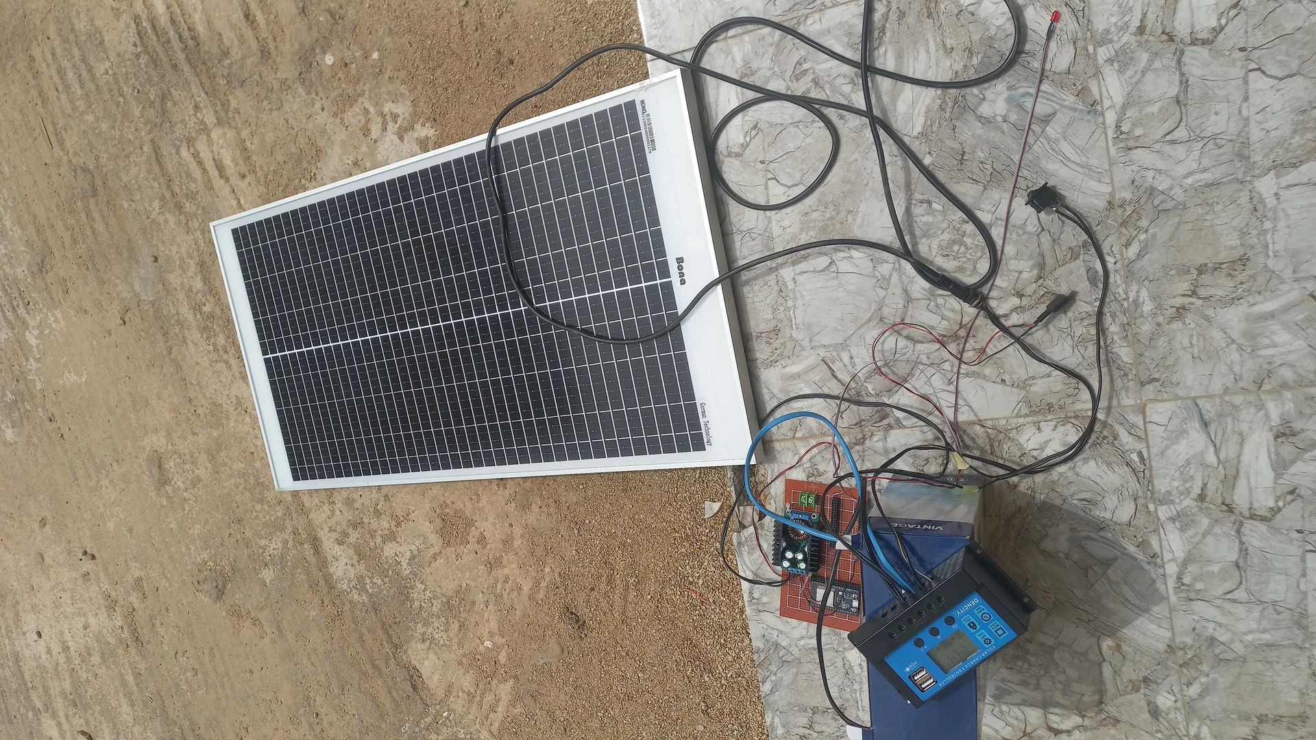
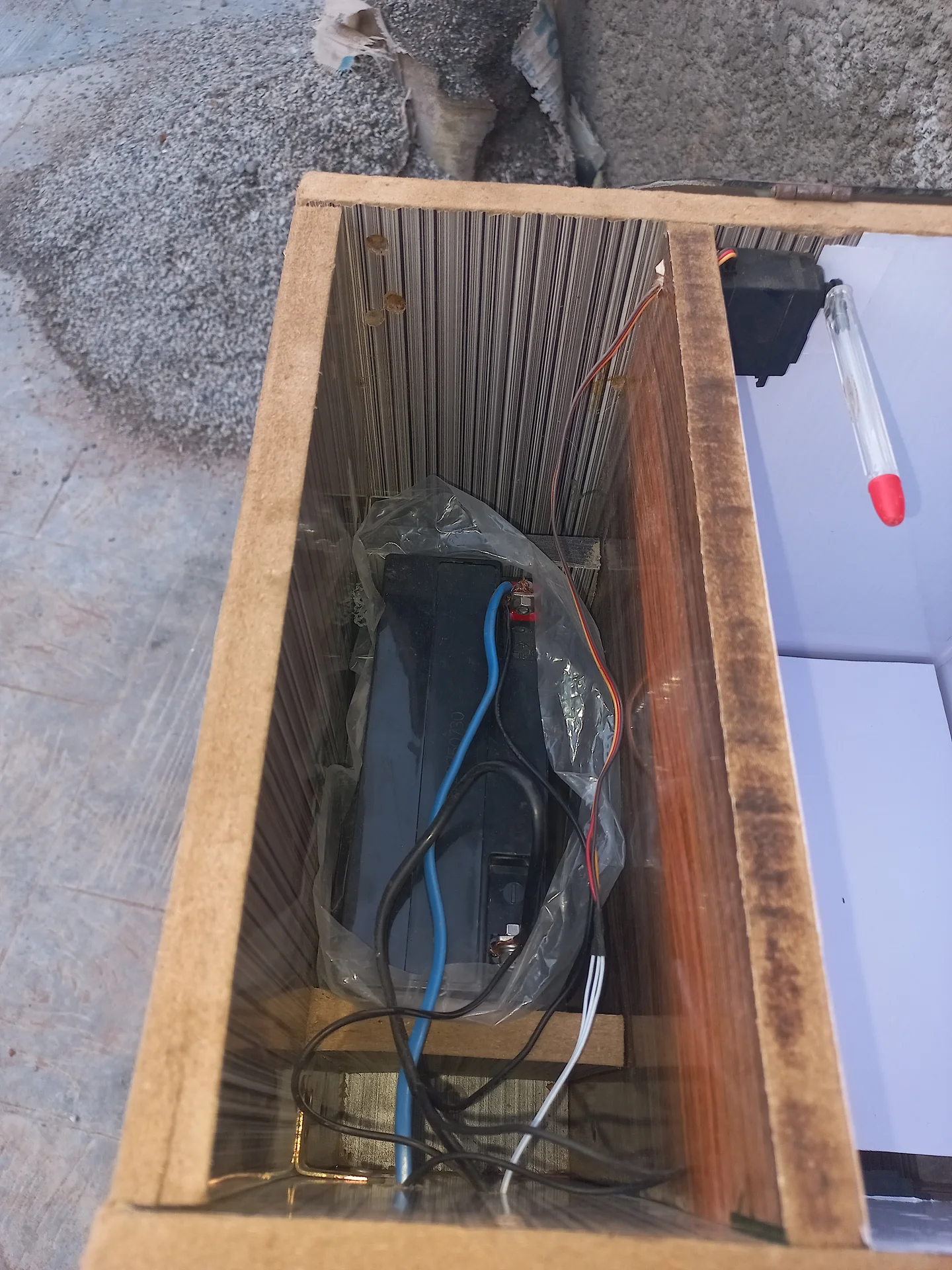
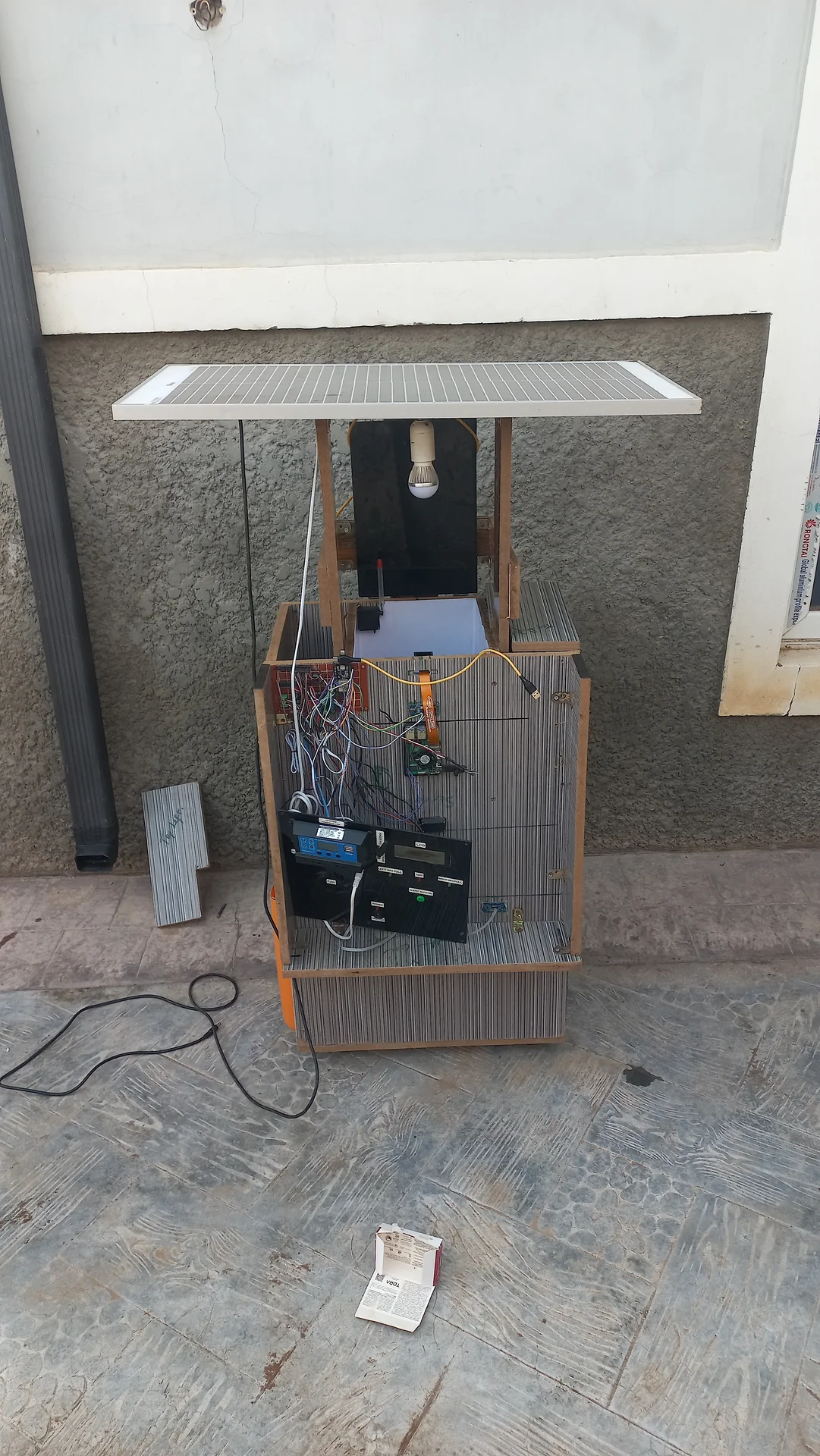
The Pi 5 displayed a lightning-bolt low-voltage warning; vcgencmd get_throttled returned 0xd0000, confirming active CPU throttling. The fix involved three steps: replacing thin jumper wires with high-gauge copper wire to lower resistance; tuning the XL4016 300W DC-DC buck converter to output 5.39–5.40 V (a deliberate over-voltage to compensate for remaining wire drop under load); and turning the current potentiometer to maximum to keep the module in Constant Voltage (green LED) mode. Stress-tested with stress -c 4 -t 60 achieving throttled=0x0.
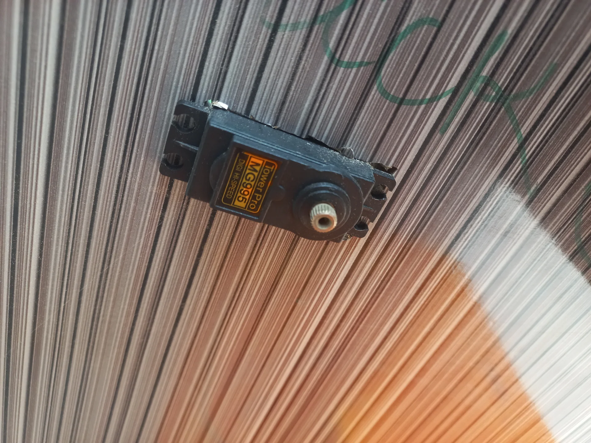
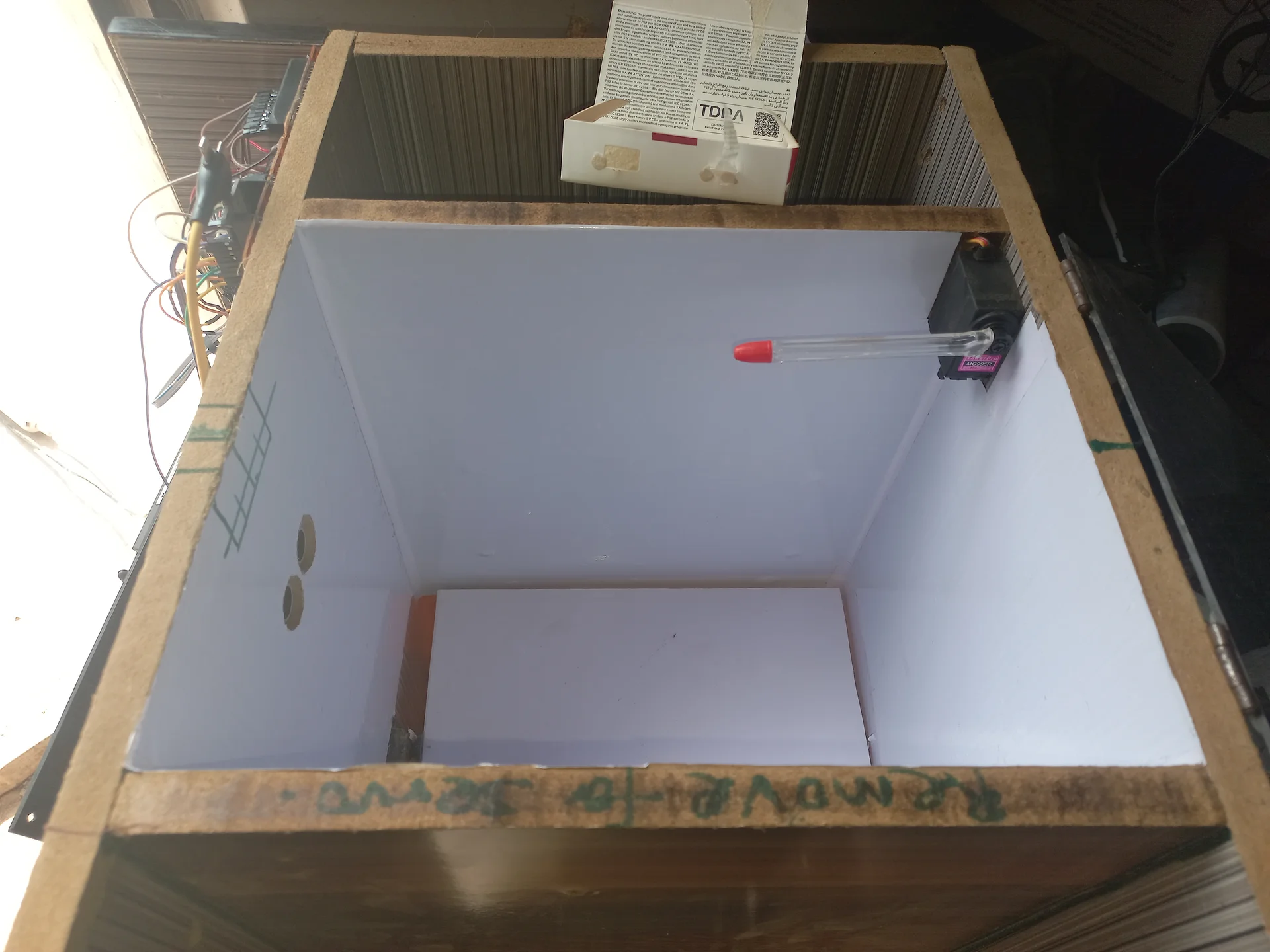
The sorting servo buzzed and shook continuously when holding the centre position because the ESP32's PWM signal made the servo motor micro-correct against gravity indefinitely. A "Quiet Mode" (Detach Logic) was implemented: moveAndDetach() attaches the servo, sweeps it to the target angle, waits 200 ms for physical arrival, then calls sortServo.detach() to cut the PWM signal entirely. The top-cover servo intentionally retains continuous attachment to maintain holding torque.
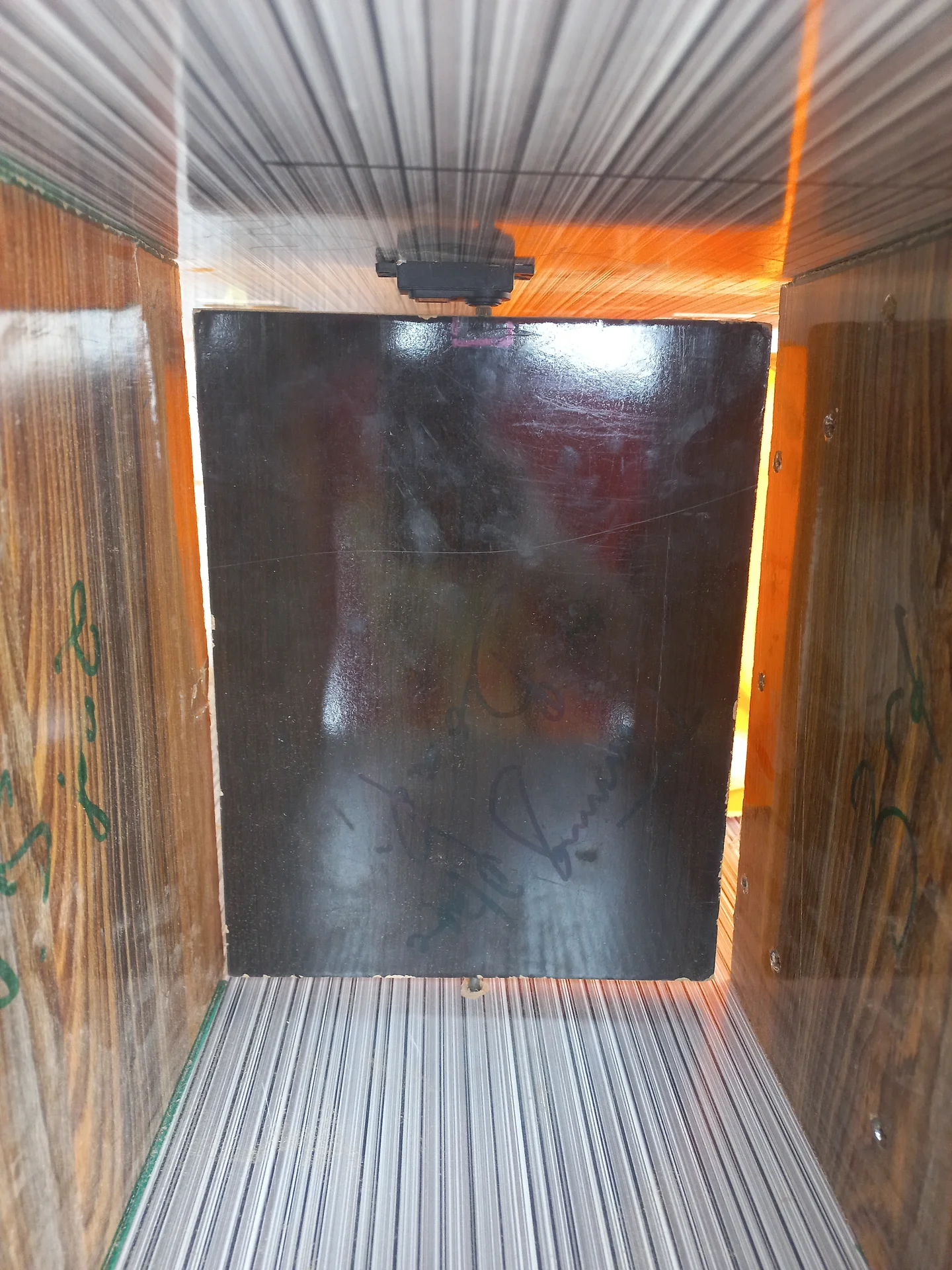
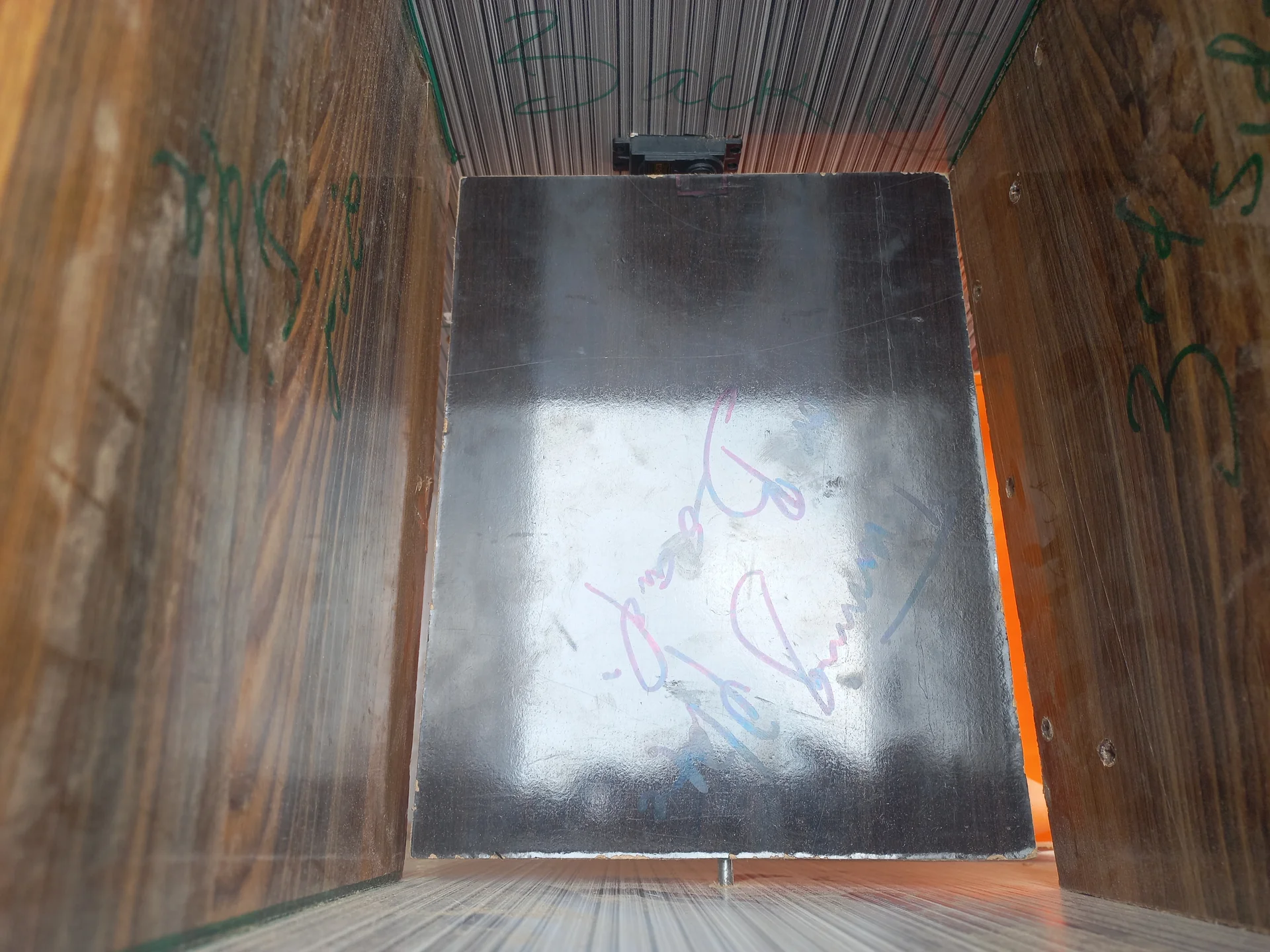
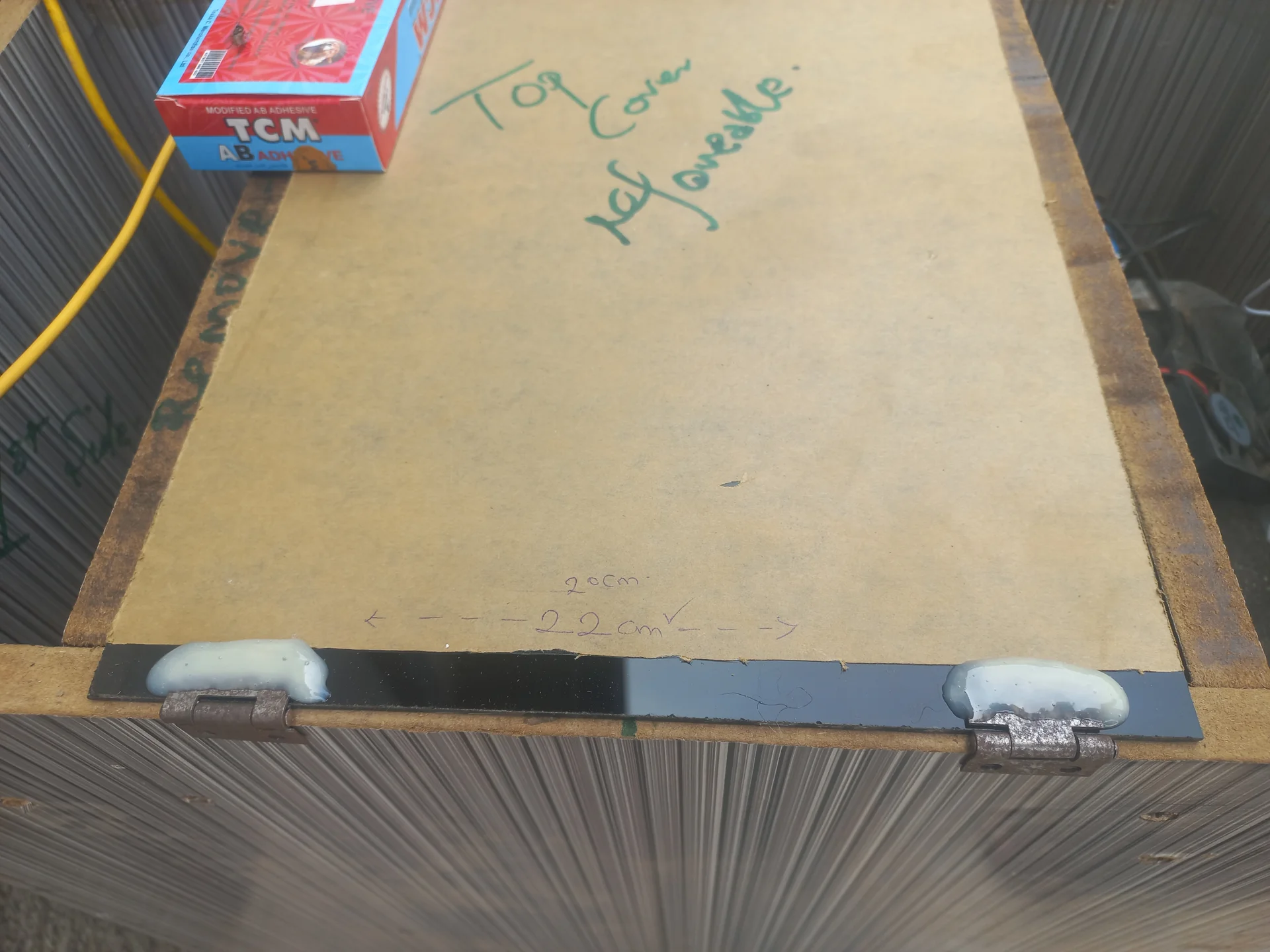
Due to how the servo horn was physically mounted, the expected open/close directions were reversed and the original per-trash-item actuation was slow and awkward. The redesign redefined 0° = OPEN, 90° = CLOSED and repurposed the cover as a System Lockout Hatch: permanently open during normal operation, closing only when a bin is full. Smooth actuation functions (openTopCover() / closeTopCover()) use 15 ms per-degree delays to prevent violent jerks.
Running YOLO continuously at 30 fps while the bin was idle caused the Pi to run hot and risk "phantom" detections (e.g., a blue shirt triggering "Plastic"). A third ultrasonic sensor in the deposit compartment solved this: when a user's hand is detected (<25 cm), the ESP32 waits 4 seconds for the hand to leave and the item to stop wobbling, then sends a single SCAN\n UART command. The Pi's 5-state machine keeps YOLO completely bypassed in WAITING and RESTING states, running inference only during SCANNING and STABILIZING.
Serial2.readStringUntil('\n') is a blocking call: a malformed message without a newline would freeze the entire ESP32 loop() for 1,000 ms, causing sensor misses and an unresponsive button. The fix was a single line in setup(): Serial2.setTimeout(50);. This caps the blocking wait at 50 ms, keeping the main loop effectively real-time.
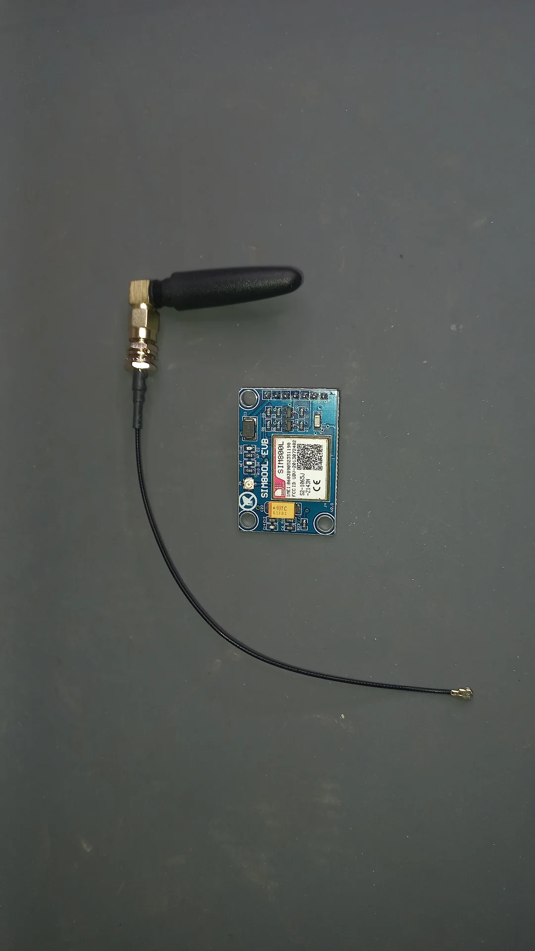
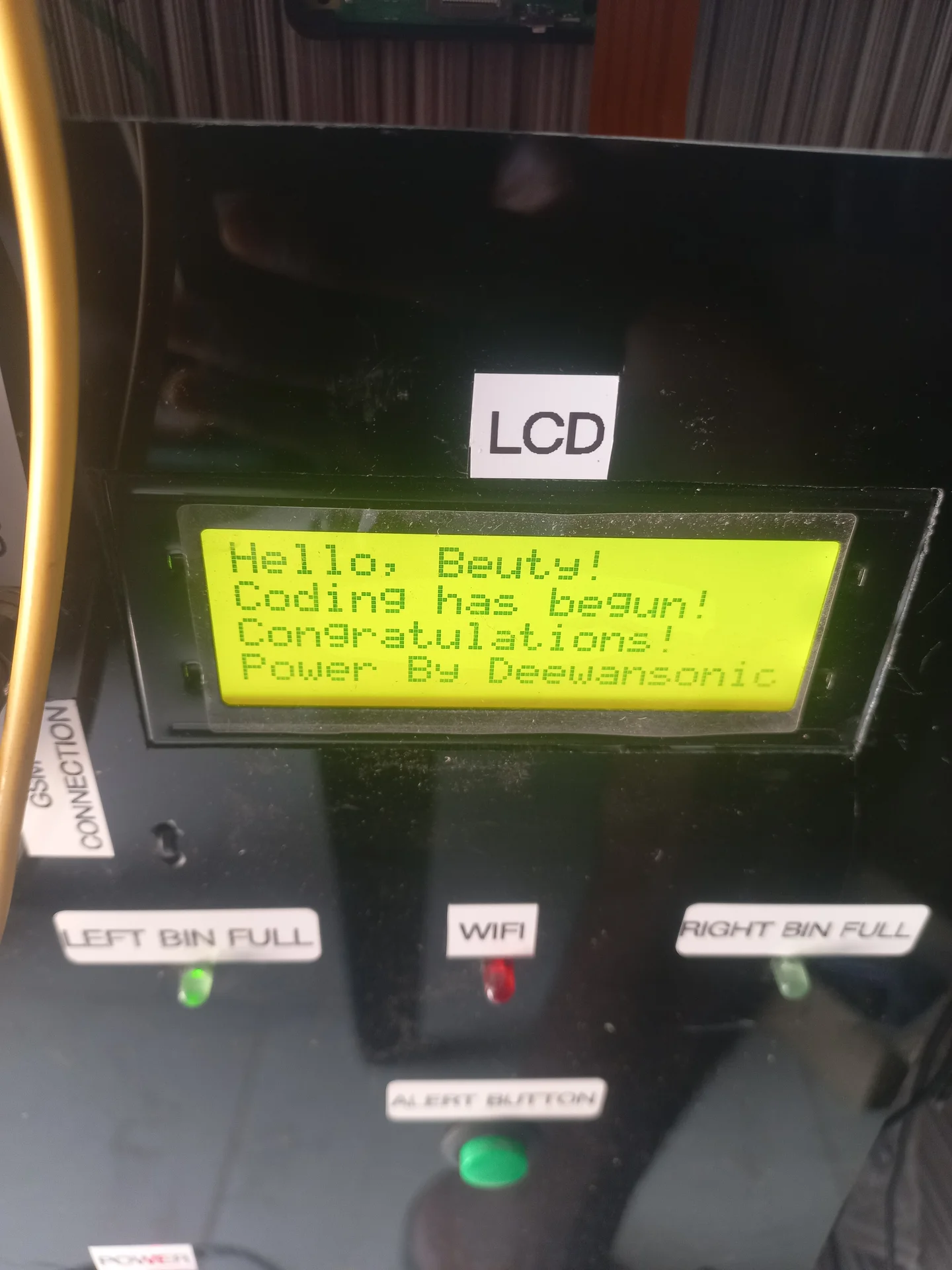
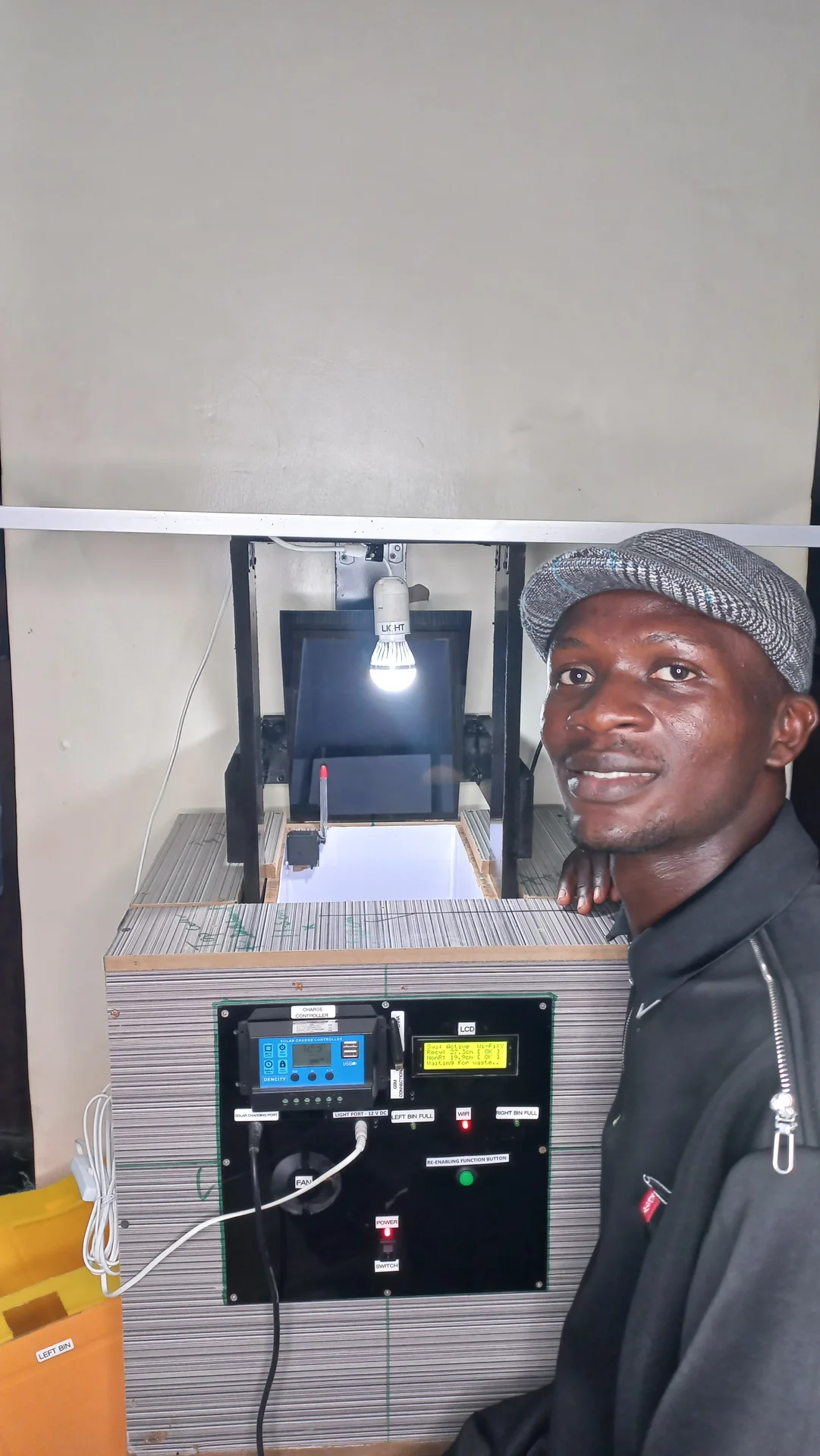
The ESP32 boots in ~1 second; the Pi takes ~30 seconds to load the OS, Python, the NCNN model, and the camera. Without synchronisation, the ESP32 had no way to know when the AI was actually ready. The Pi script sends READY\n the moment initialisation completes, followed by WIFI_OK\n or WIFI_NO\n after pinging Google DNS. The ESP32 catches these signals and advances the LCD through a multi-stage splash screen, finally settling on "Waiting for waste..".
Even after a janitor empties a full bin, the sensor instantly reads clear. If the code unlocked automatically, any debris falling over could trigger infinite lock/unlock loops. The design requires manual acknowledgment: leftBinLocked stays true until the janitor presses the physical push button (Pin 13). A 50 ms debounce filter ensures clean presses. On press, all lock booleans and SMS flags are reset, the buzzer beeps once to confirm, and the top cover sweeps open.
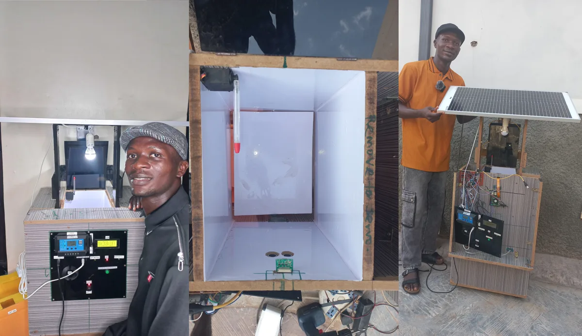
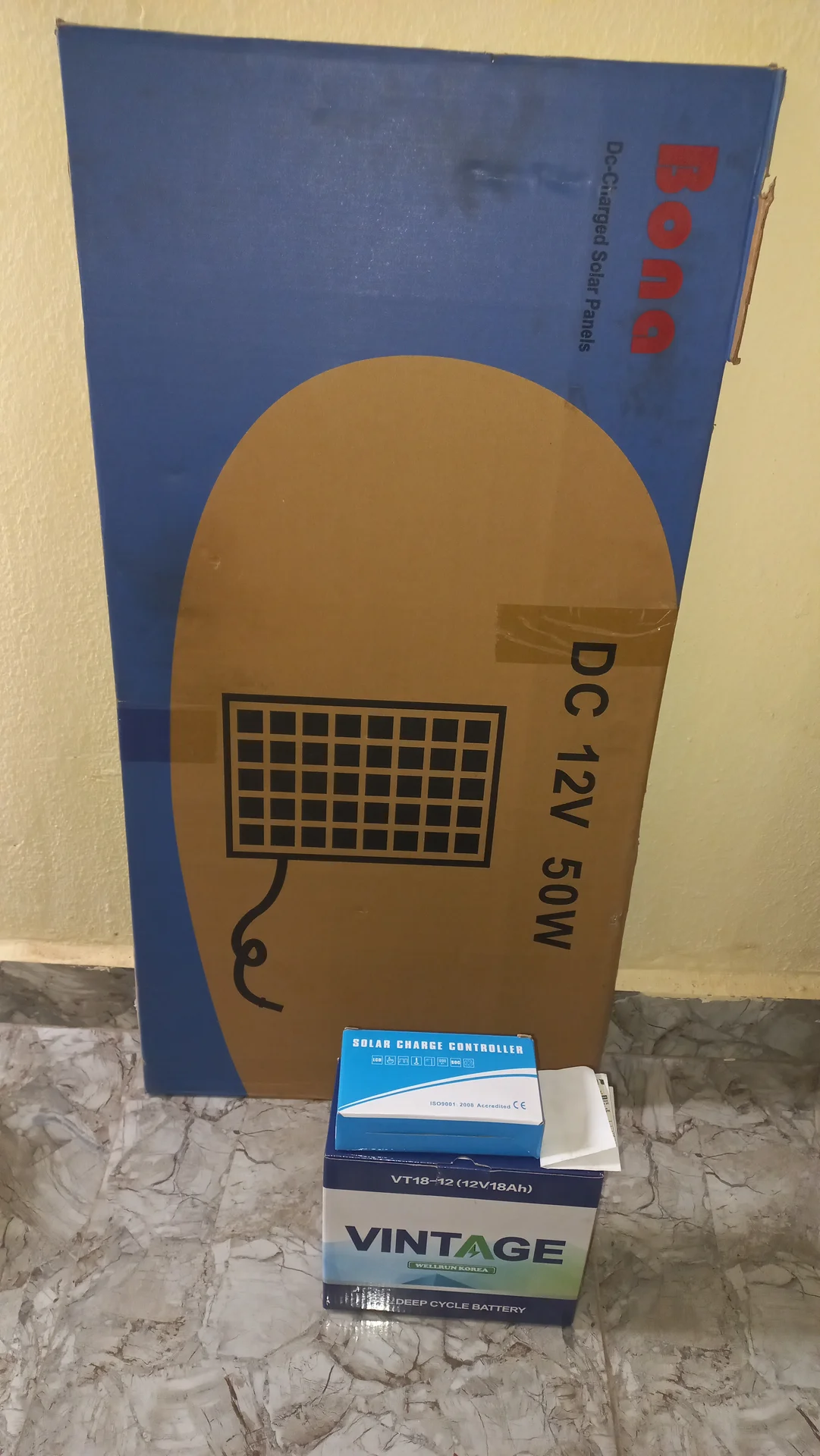
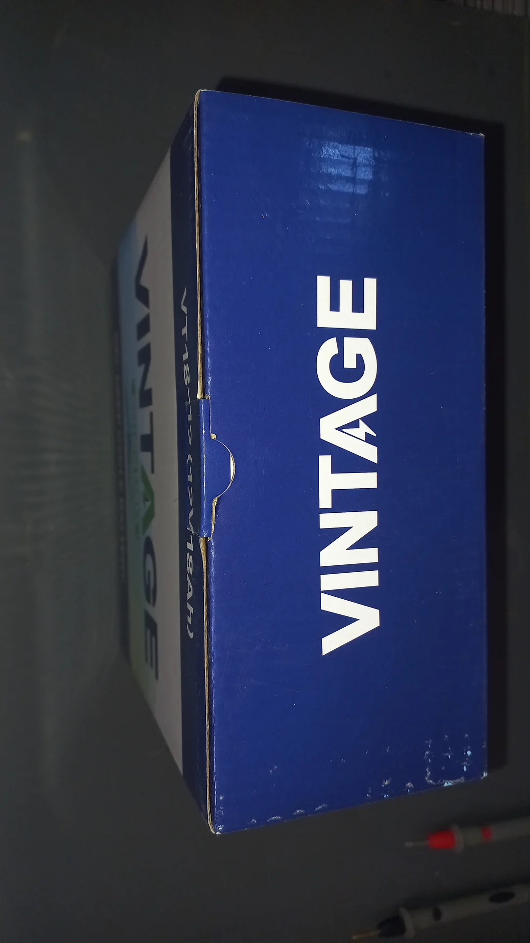
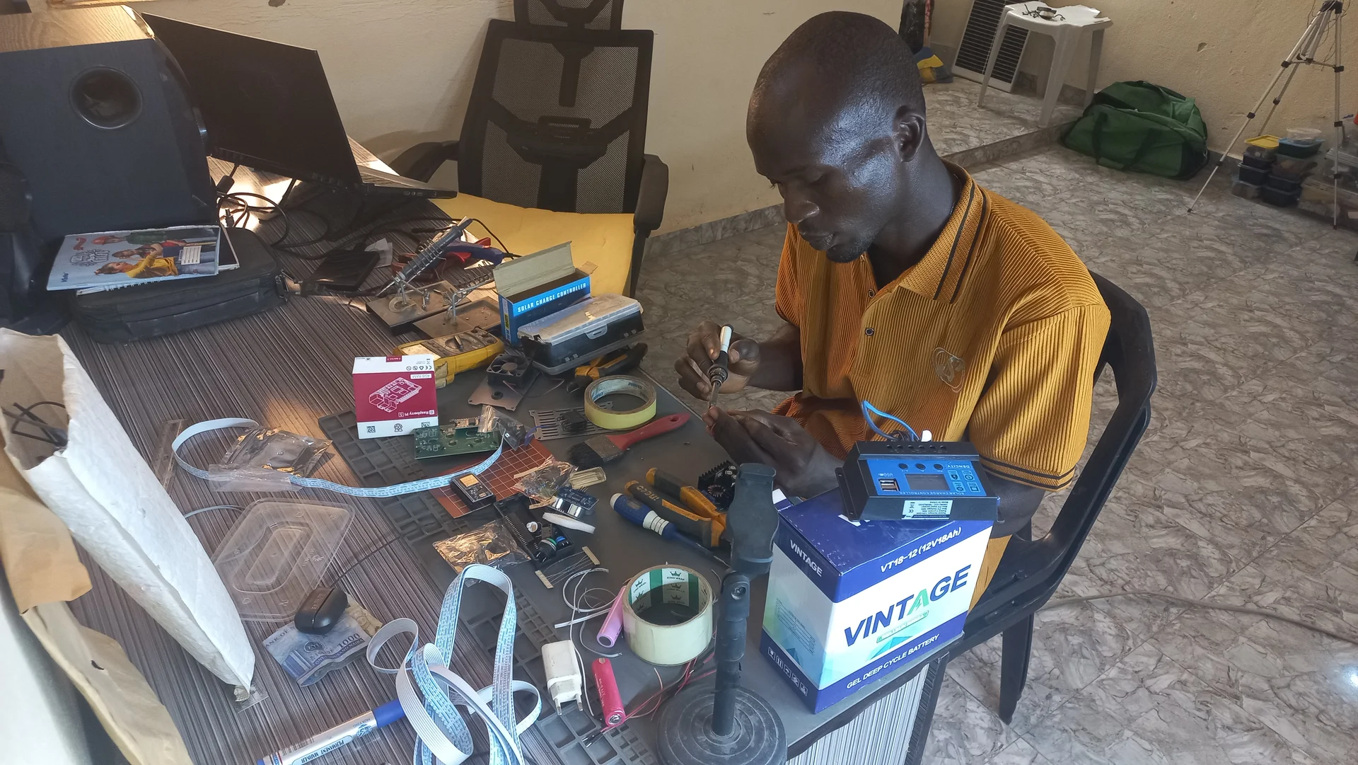
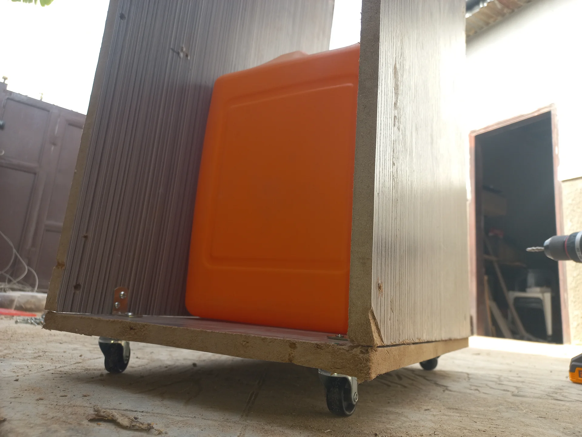
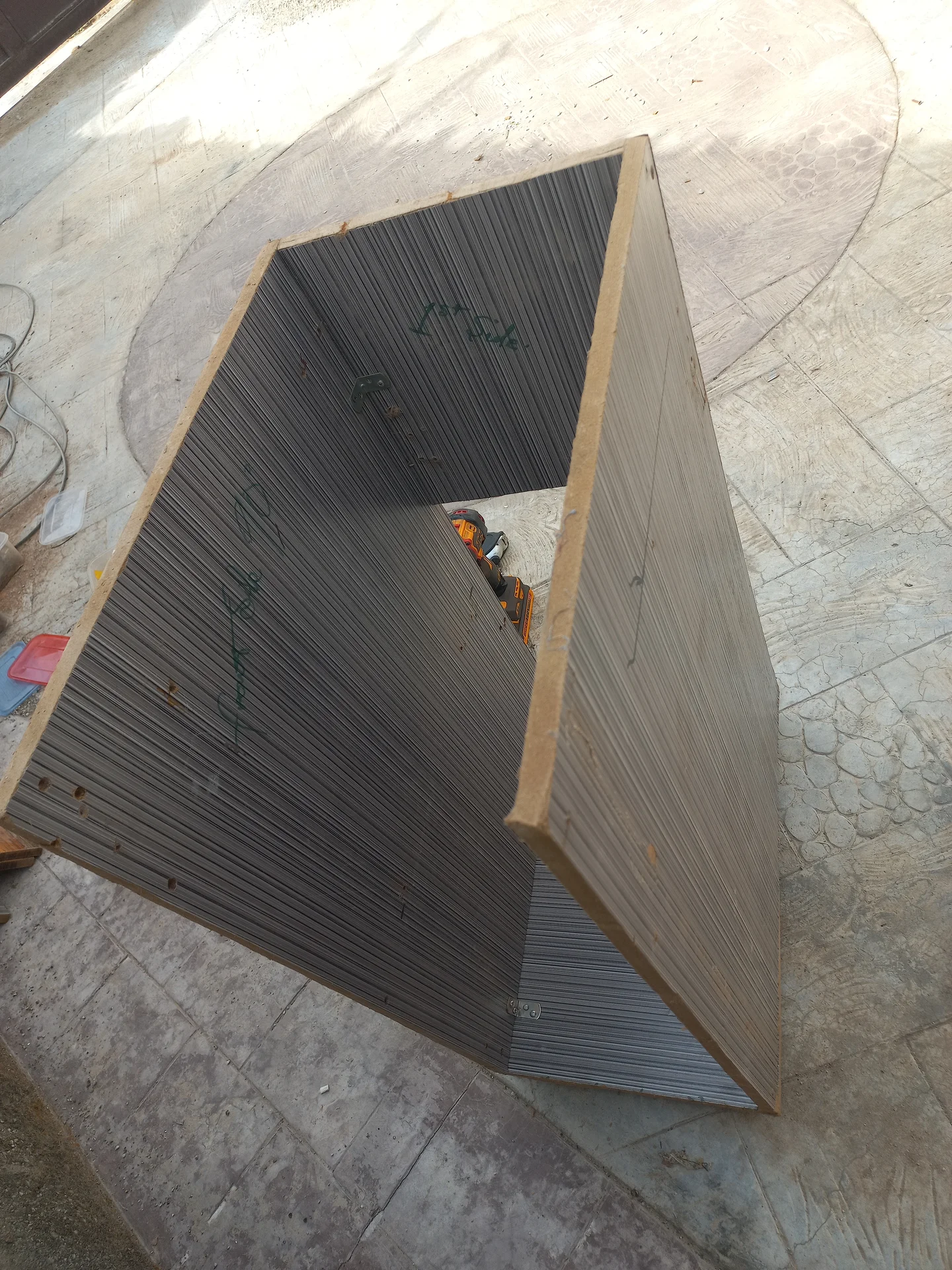
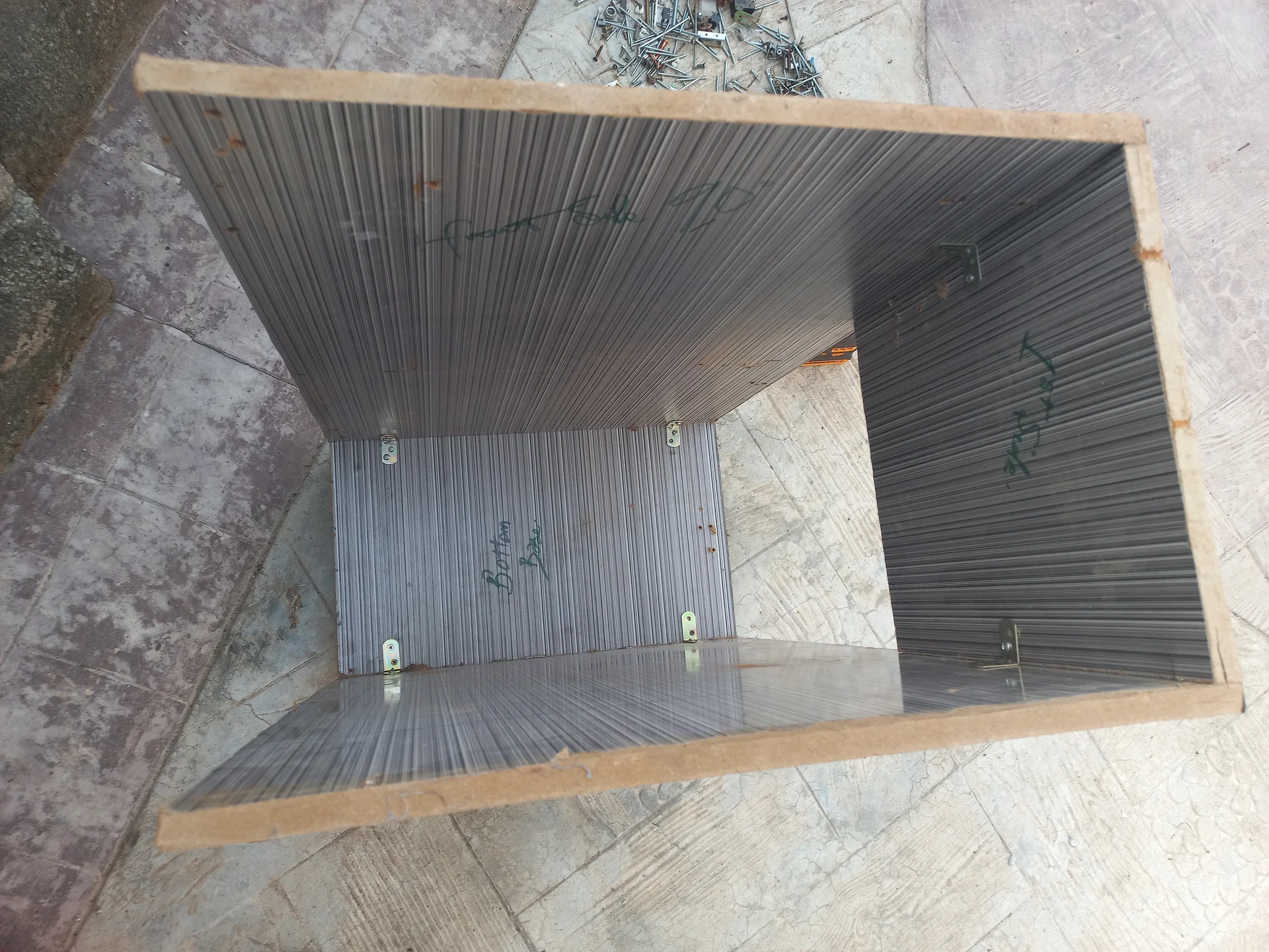
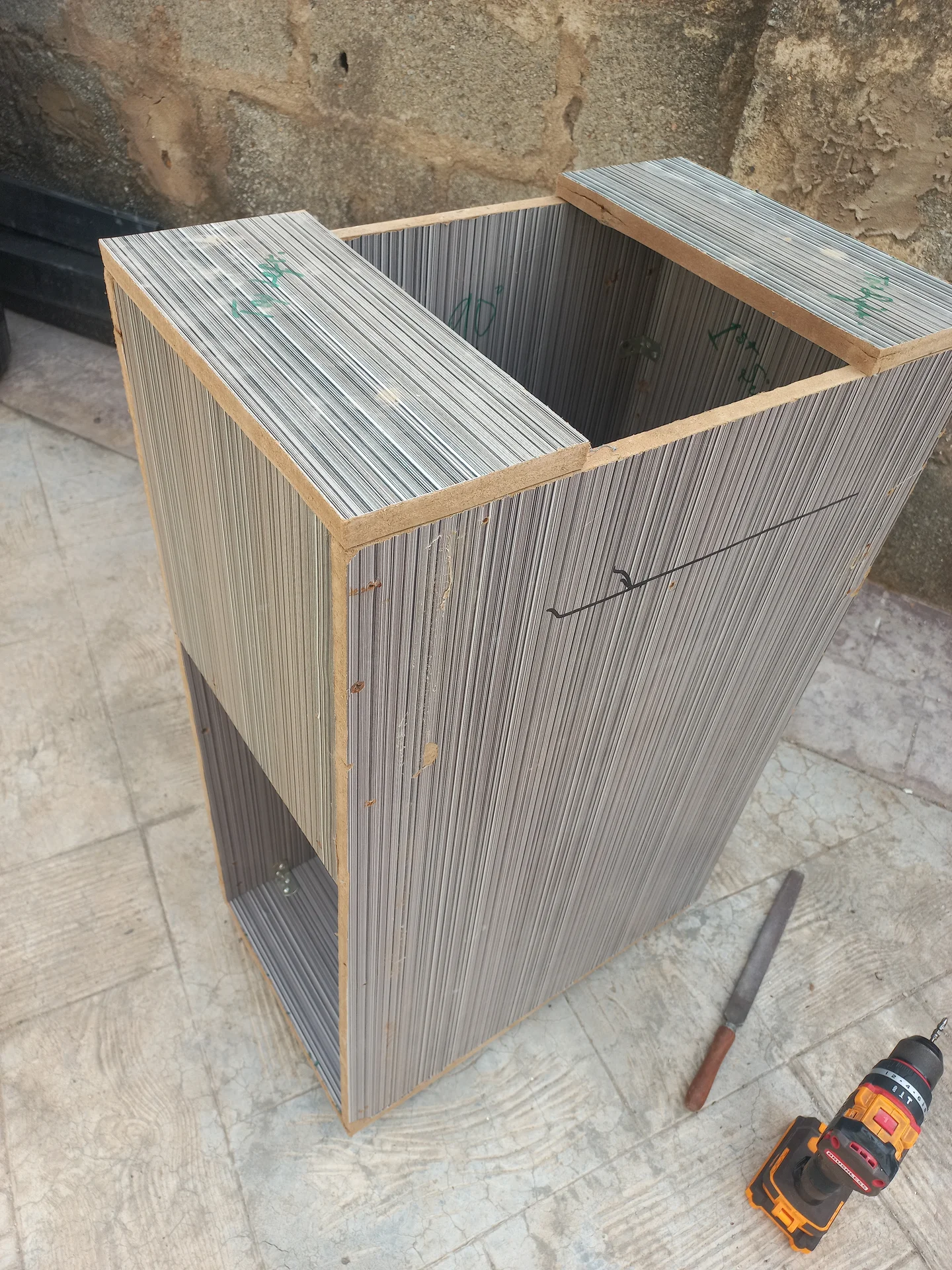
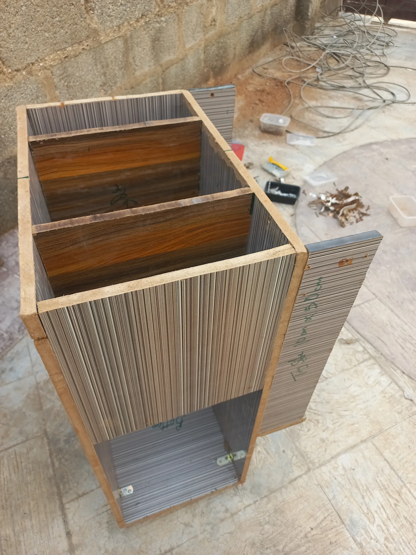
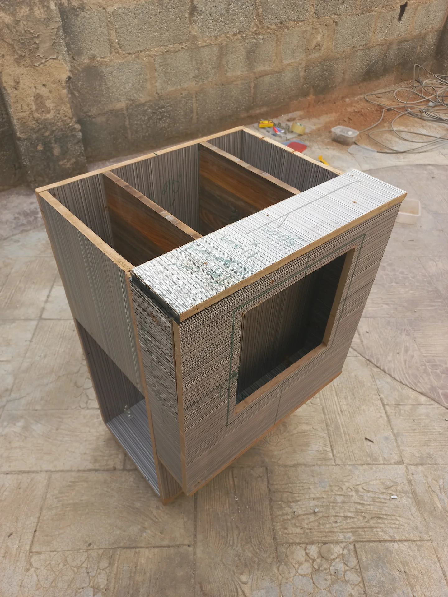
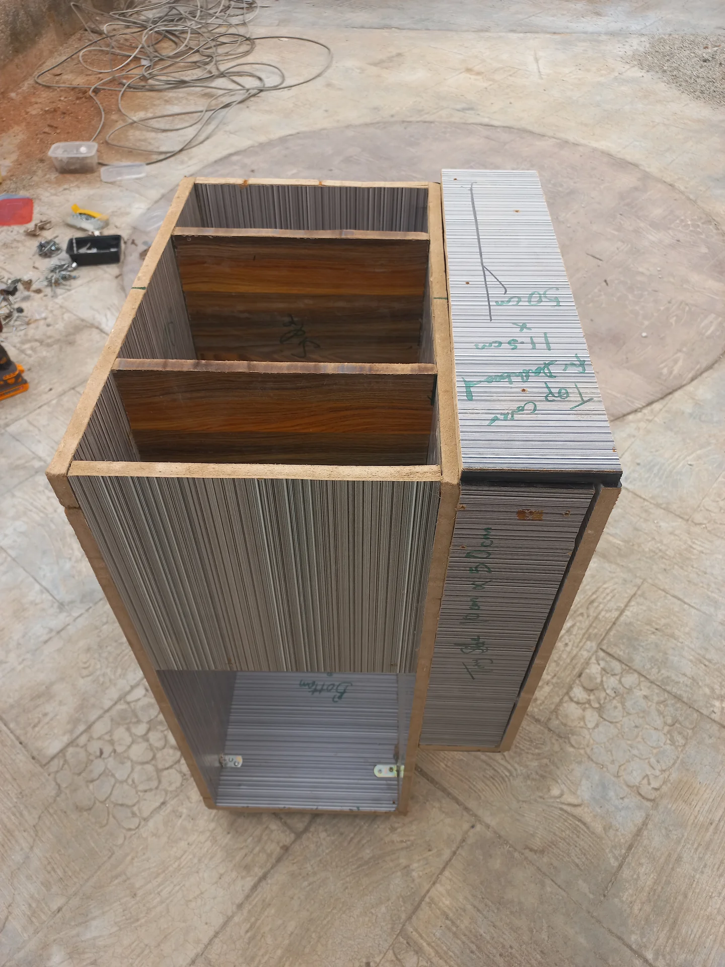
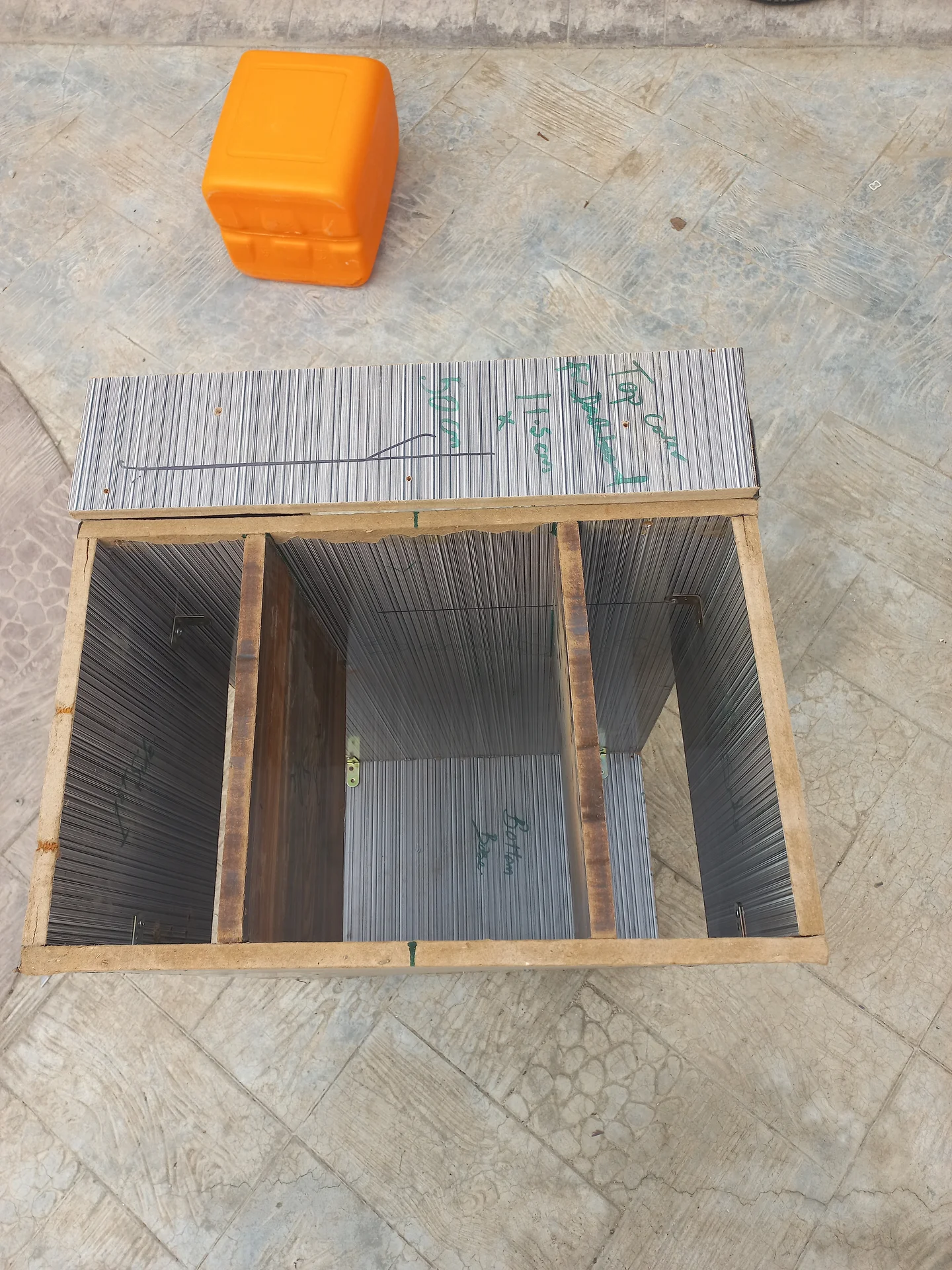
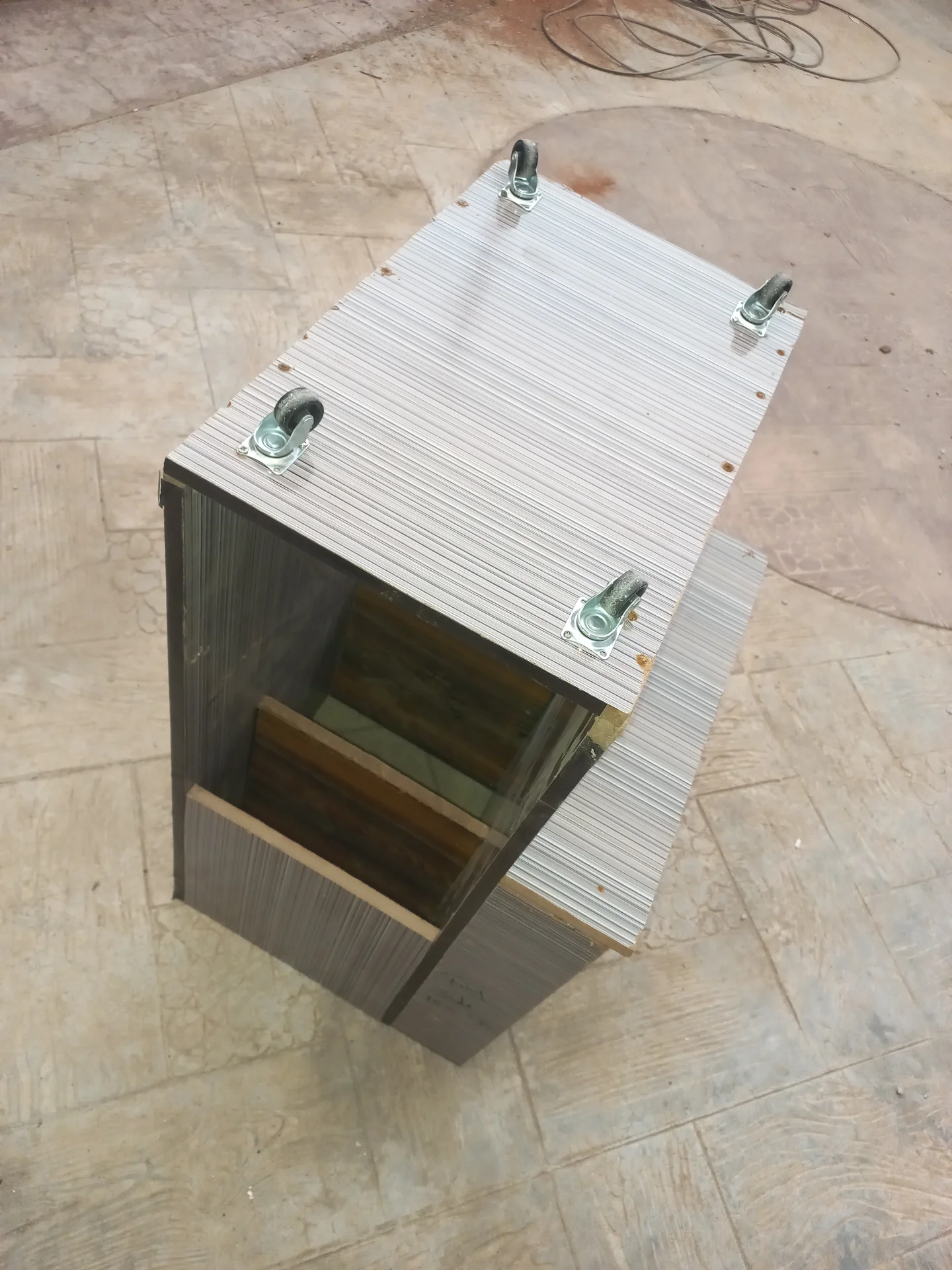
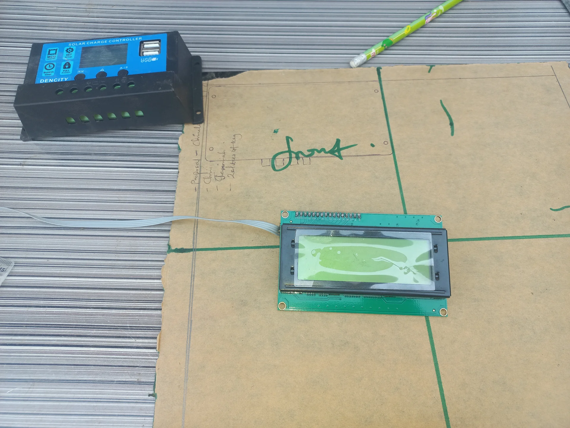
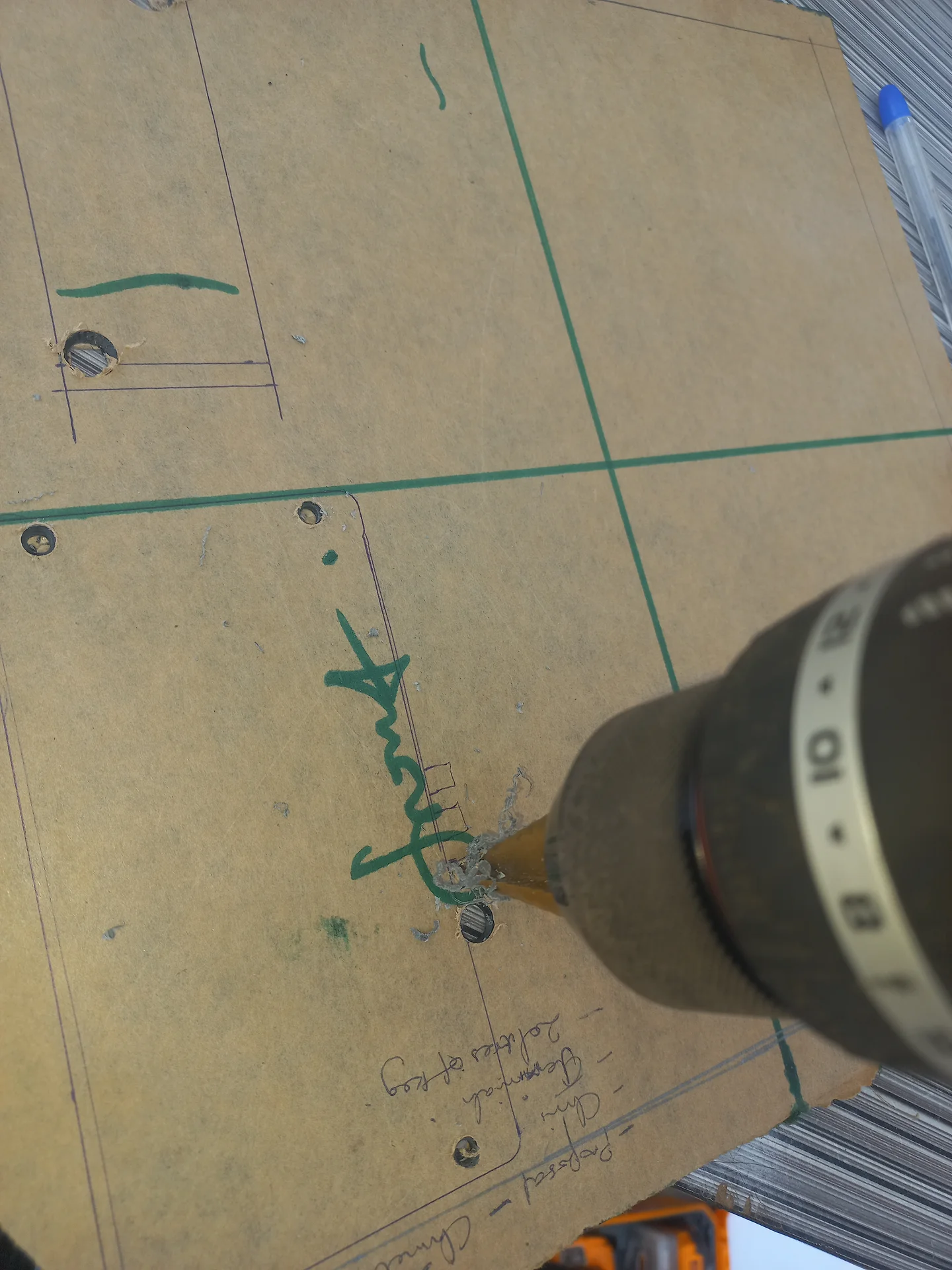
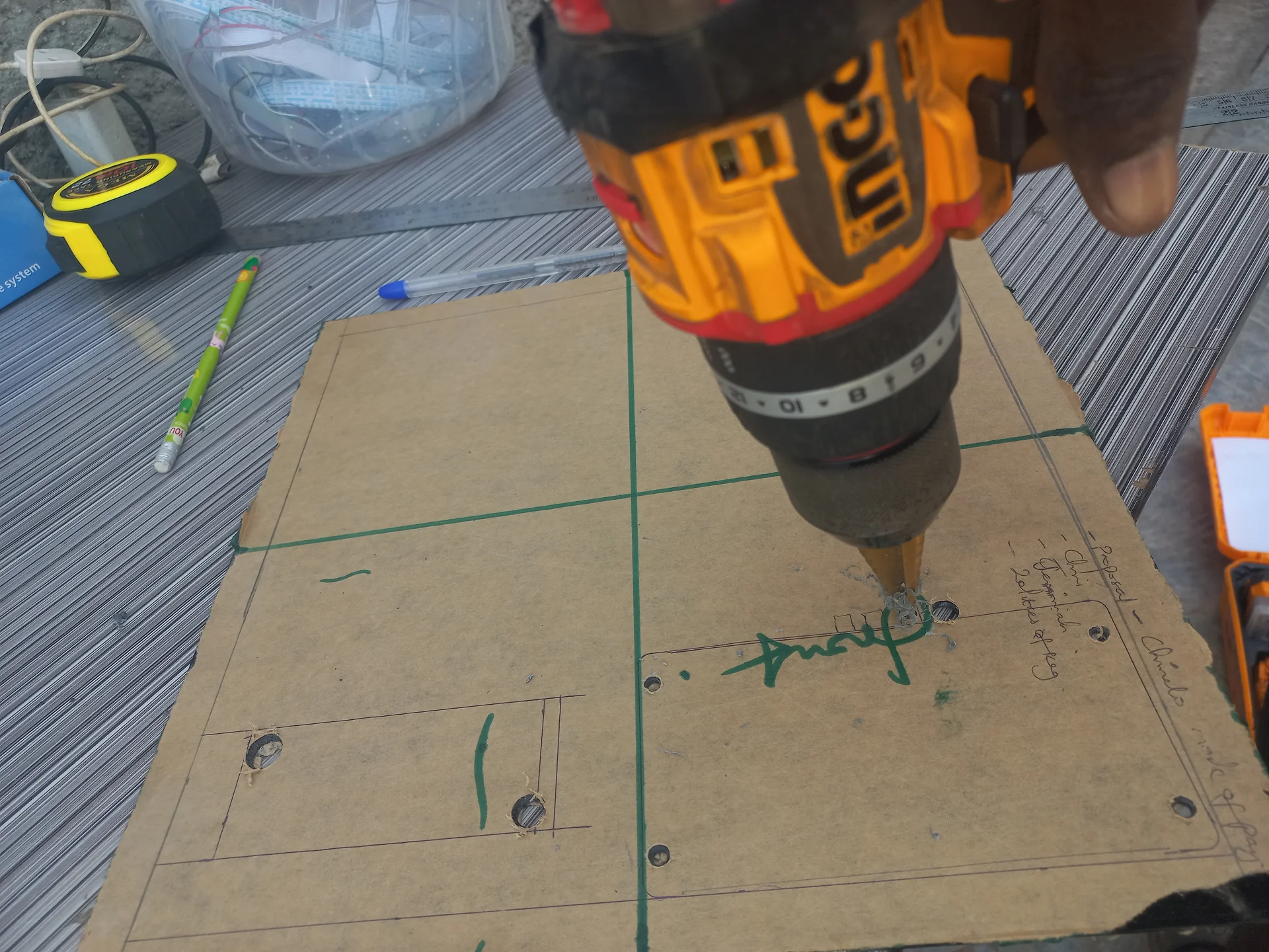
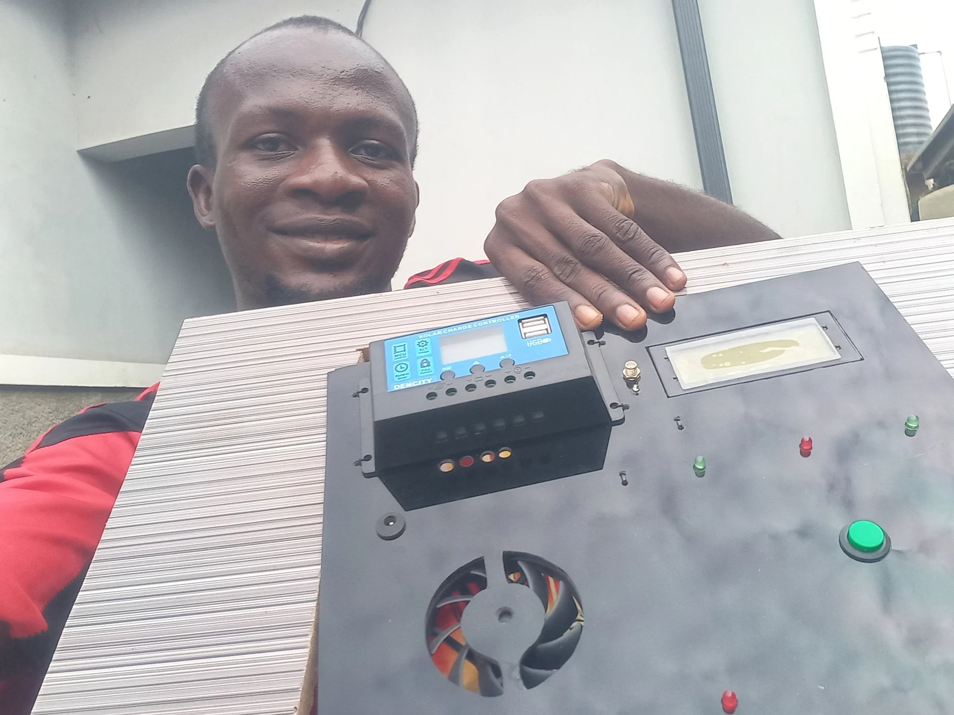
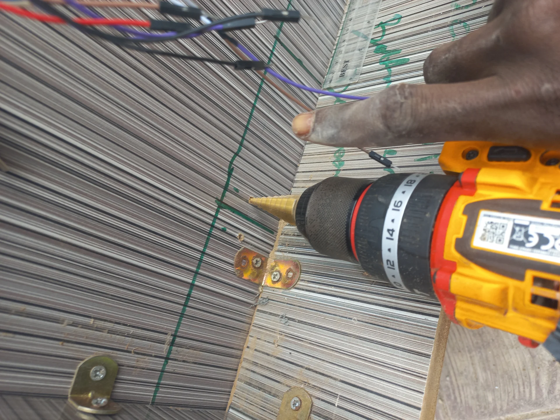
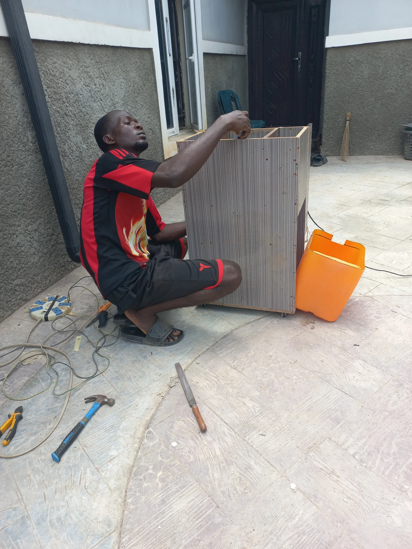
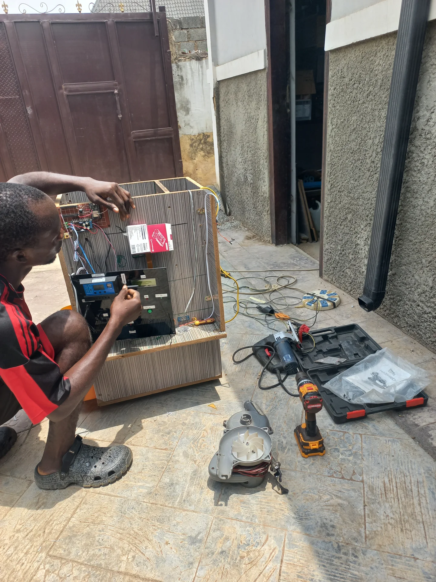
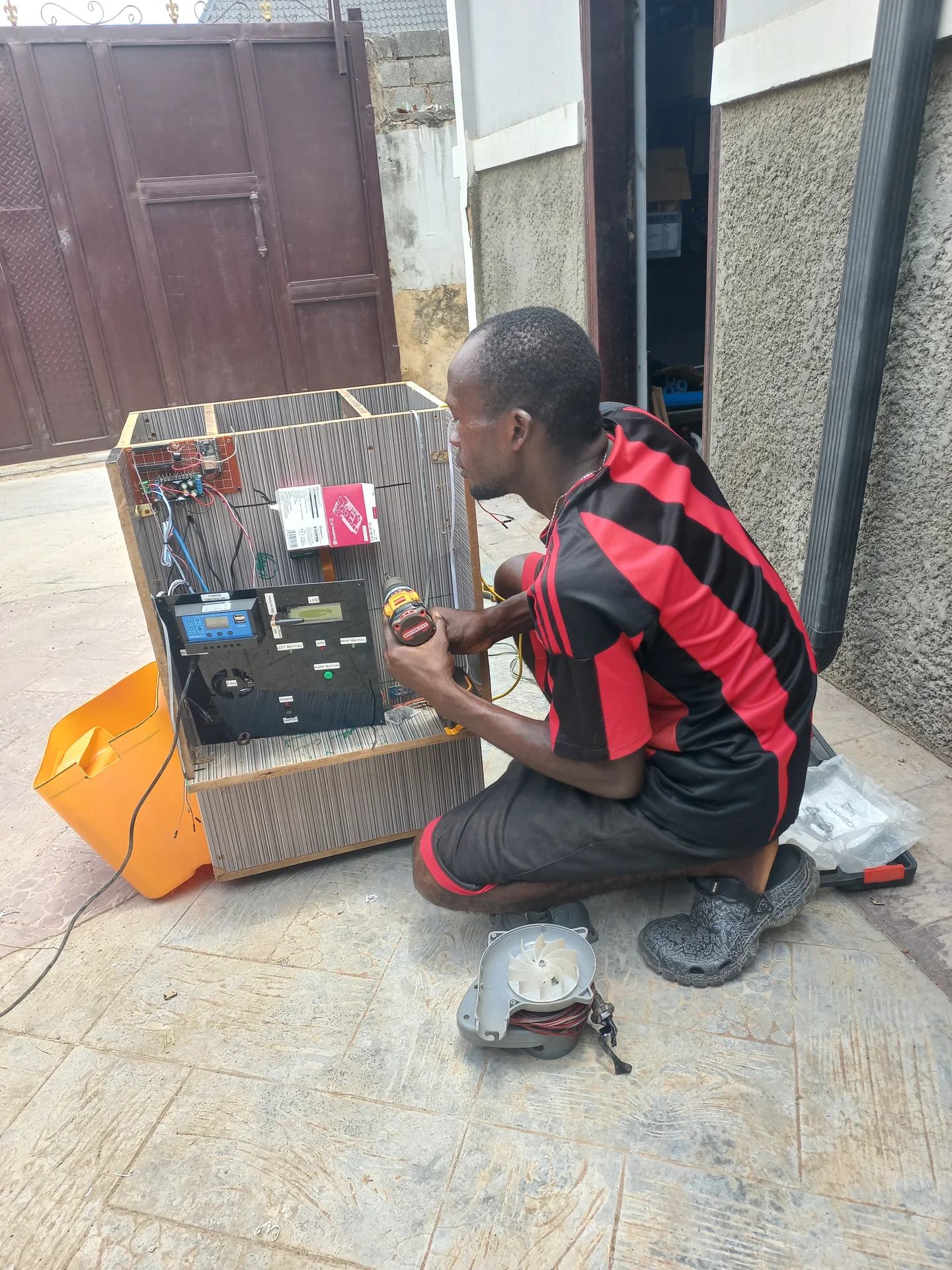
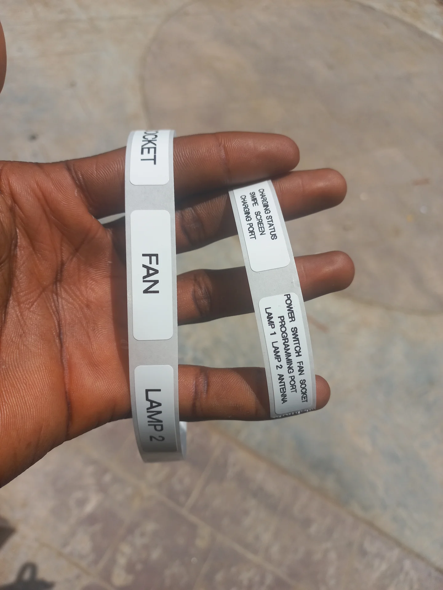
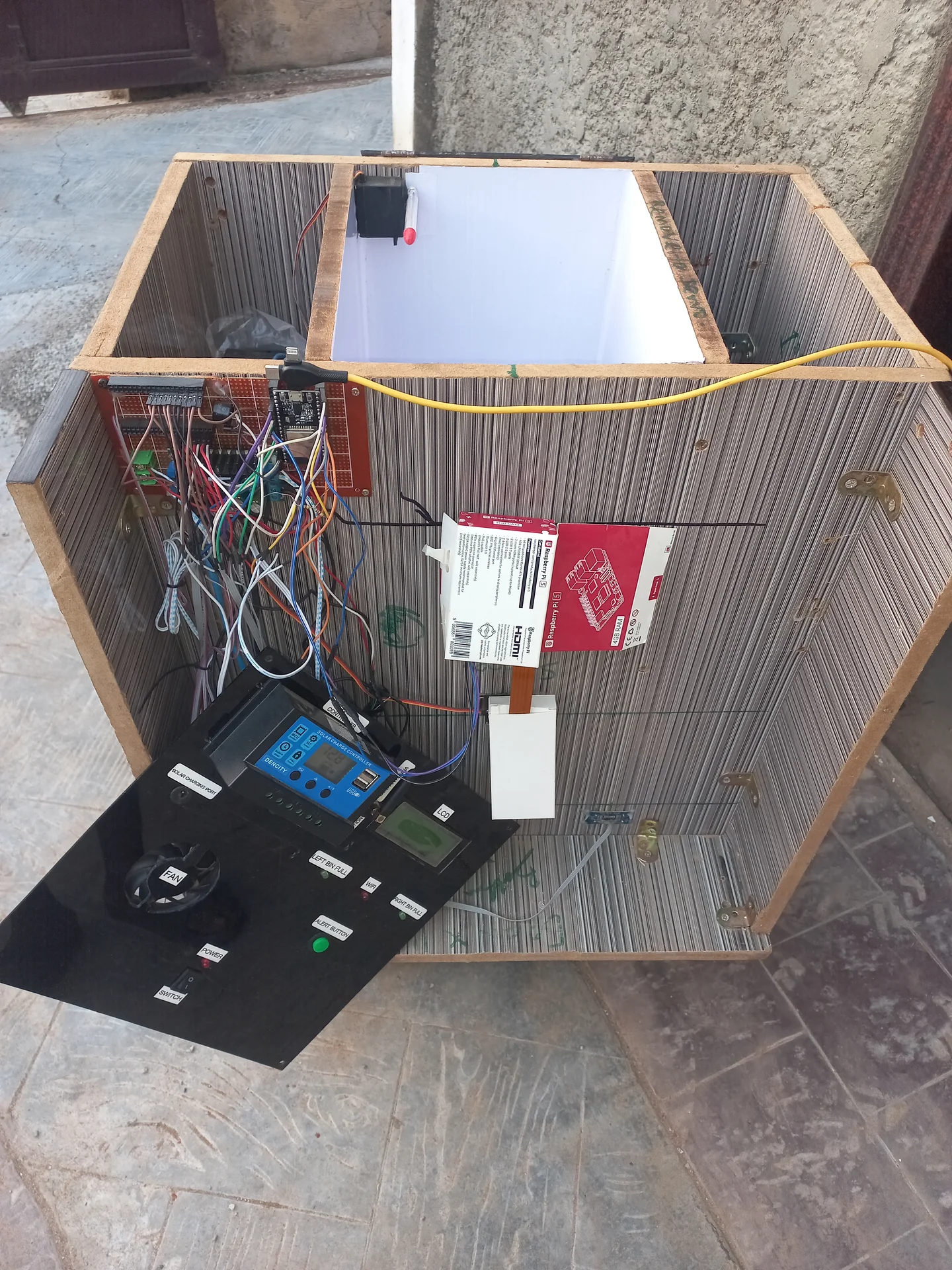
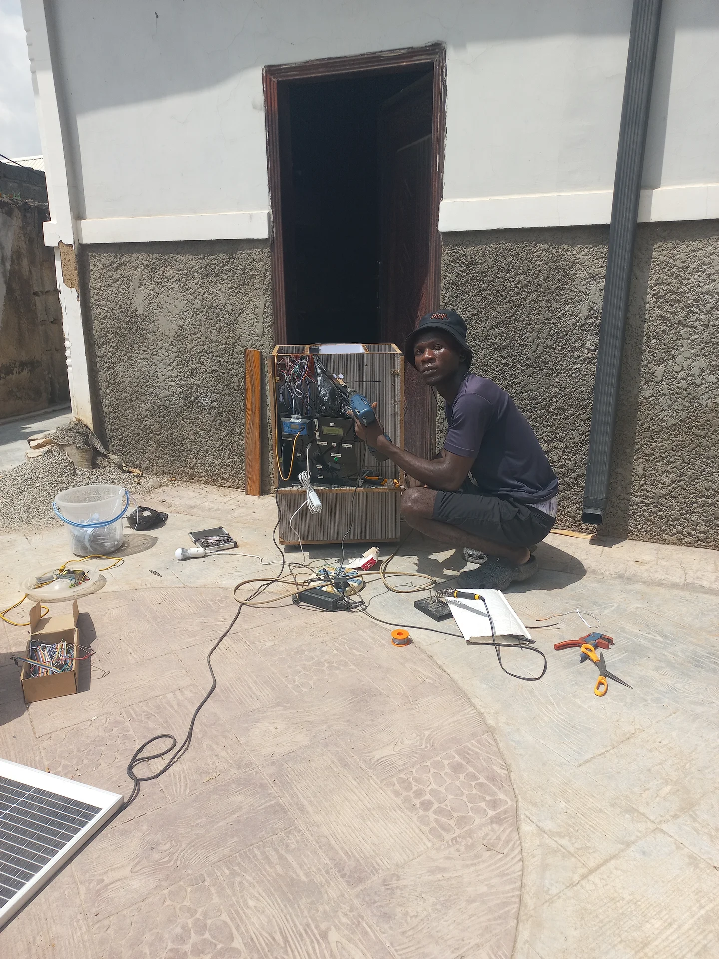
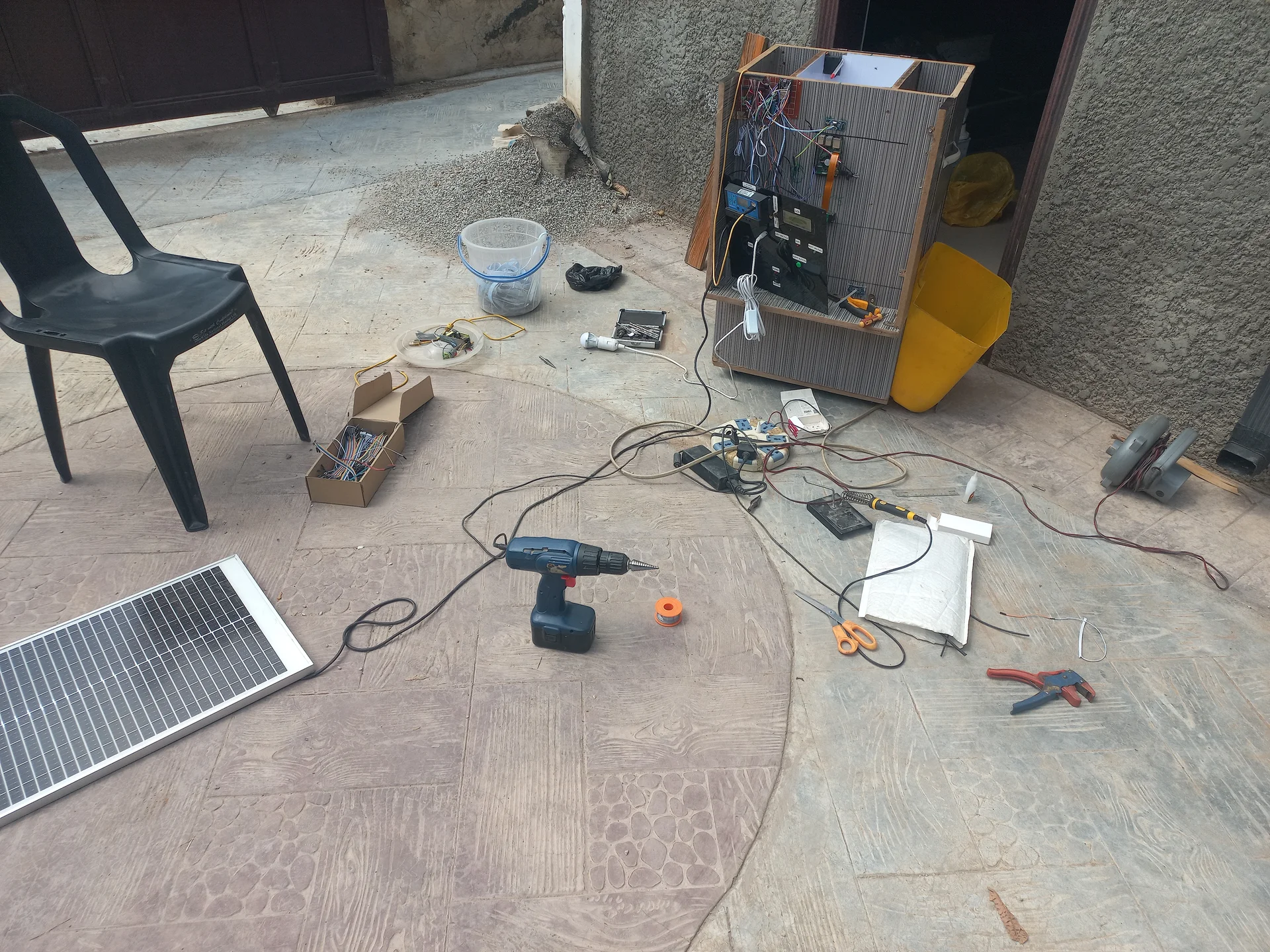
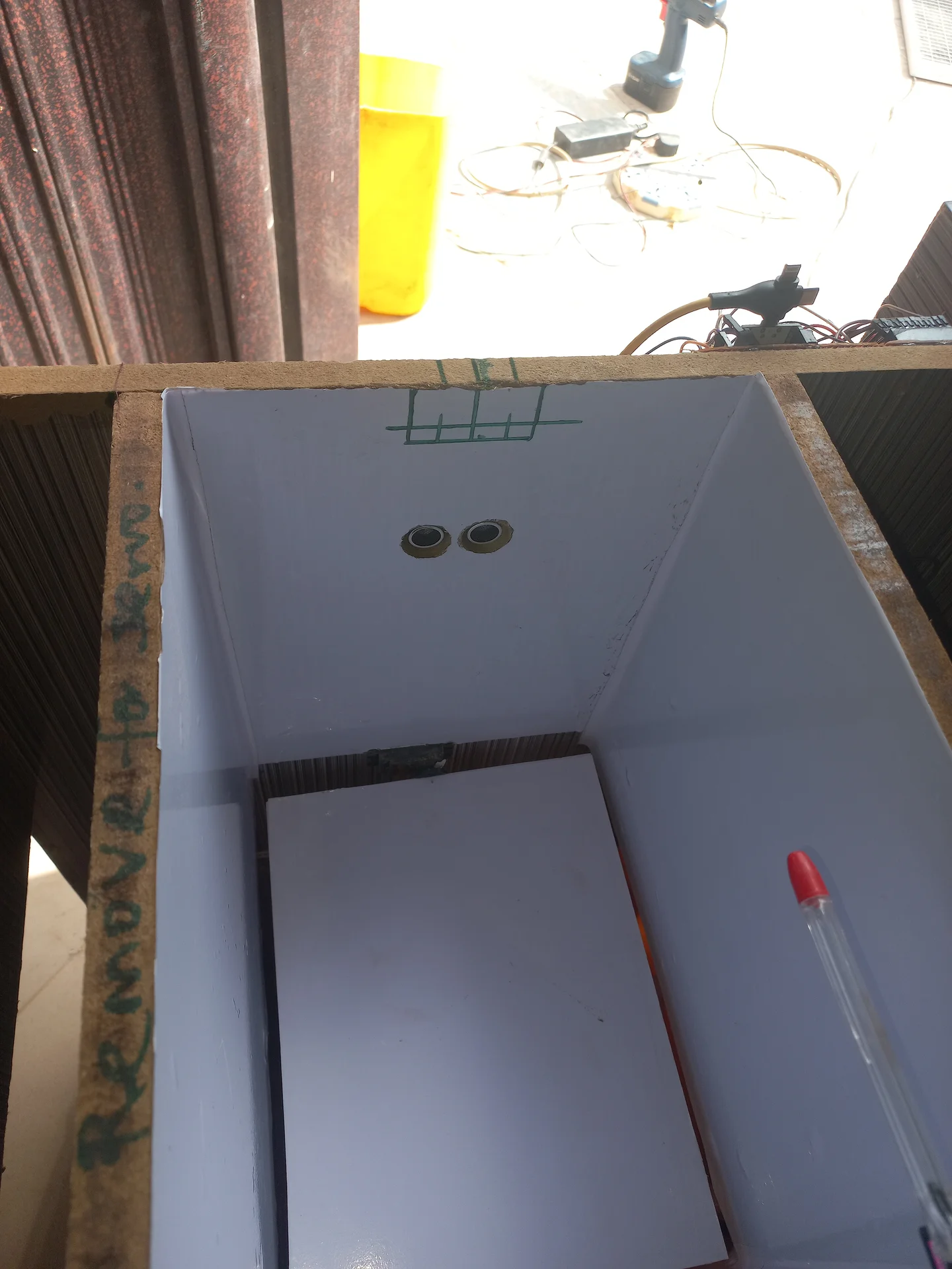
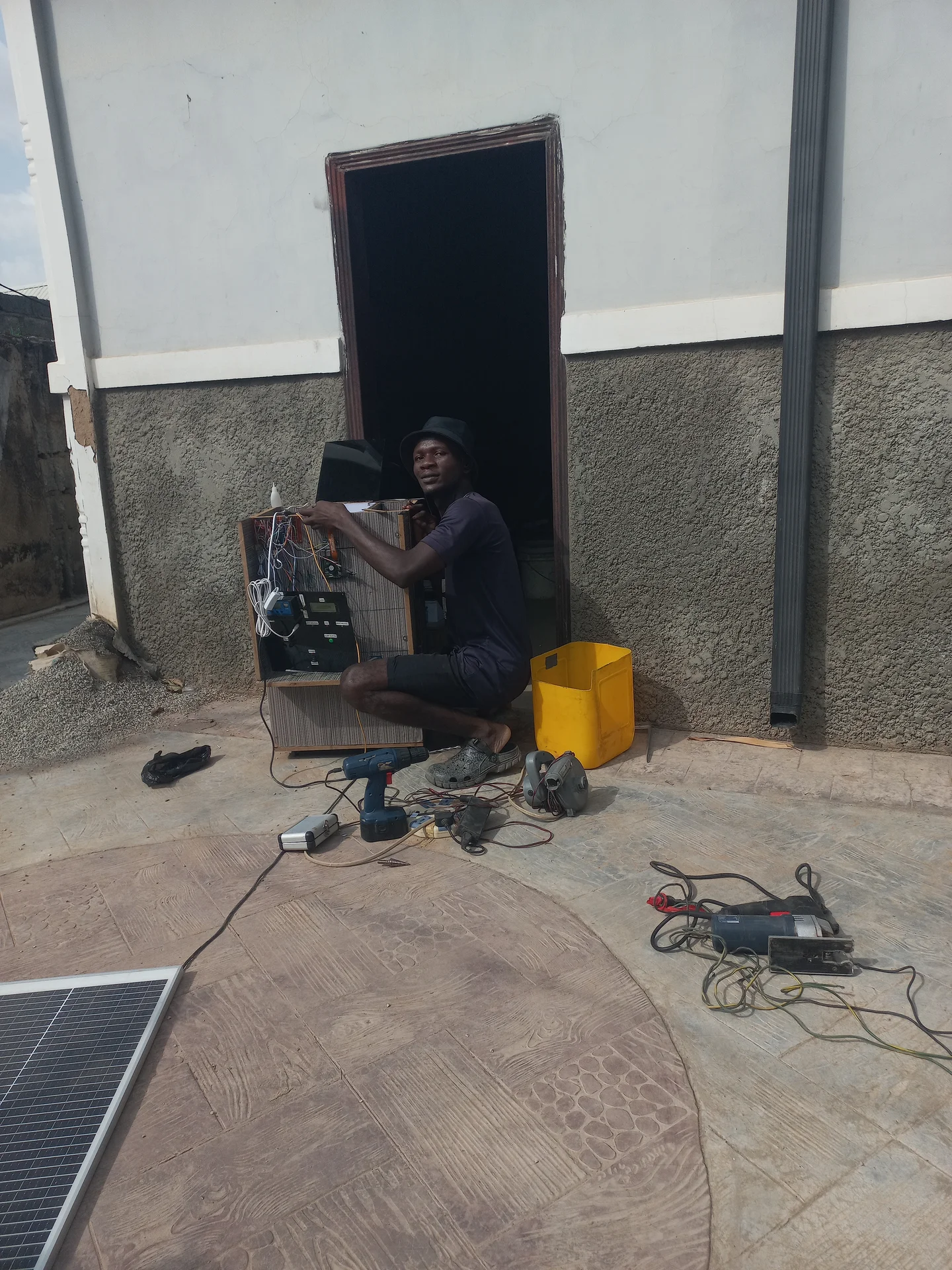
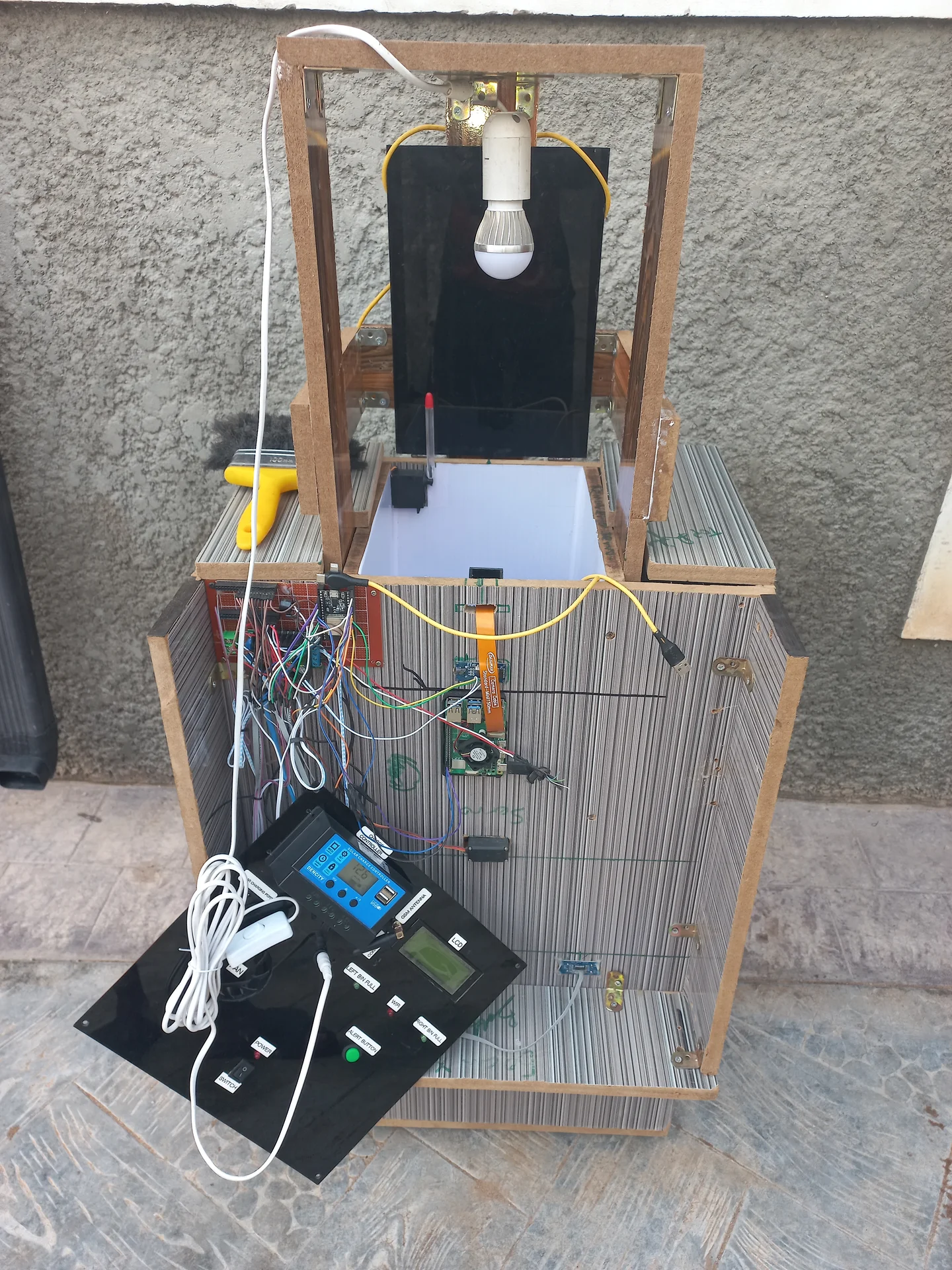
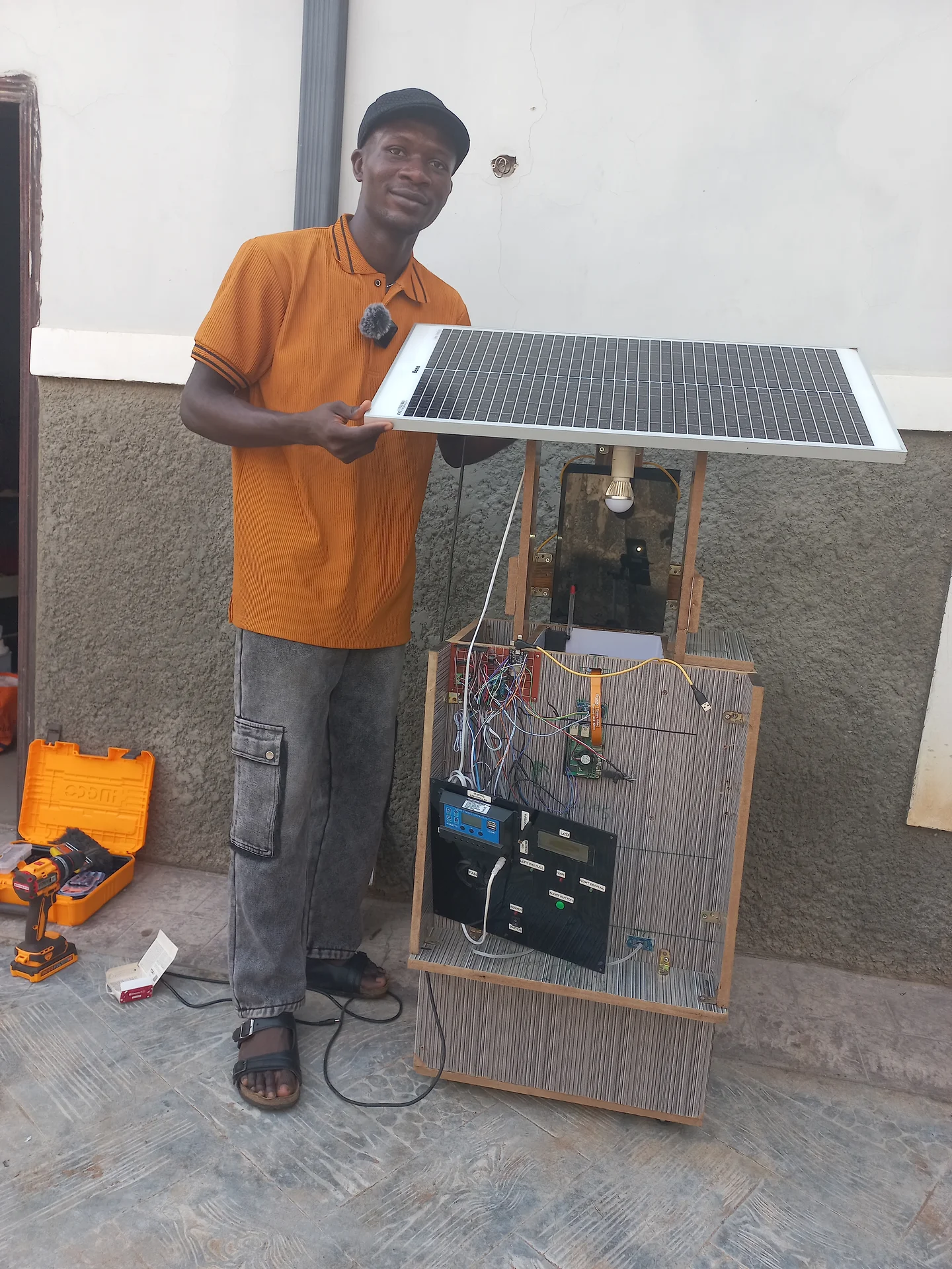
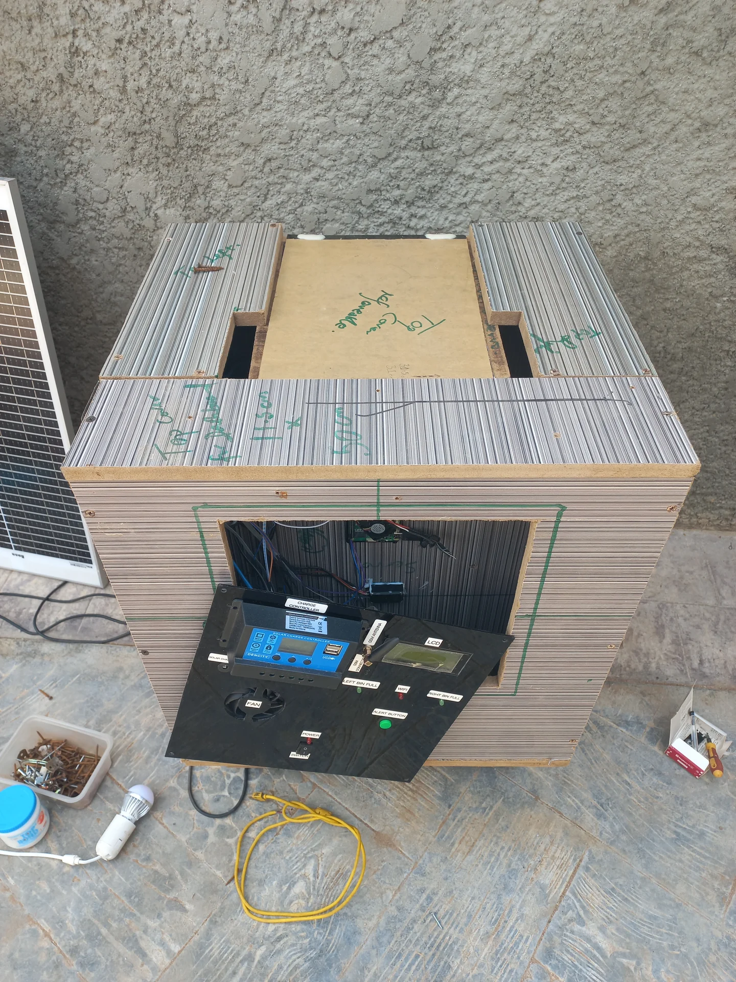
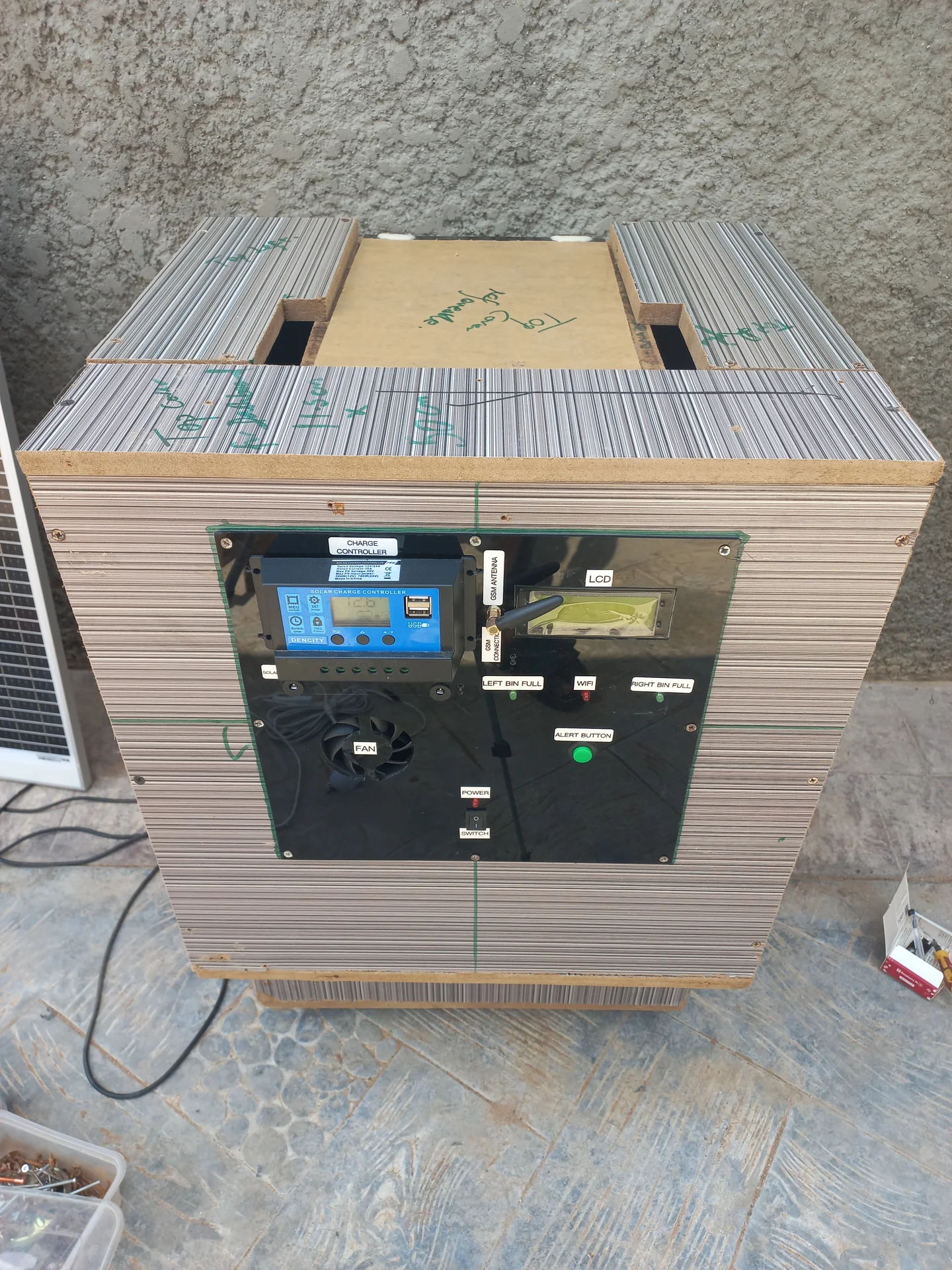
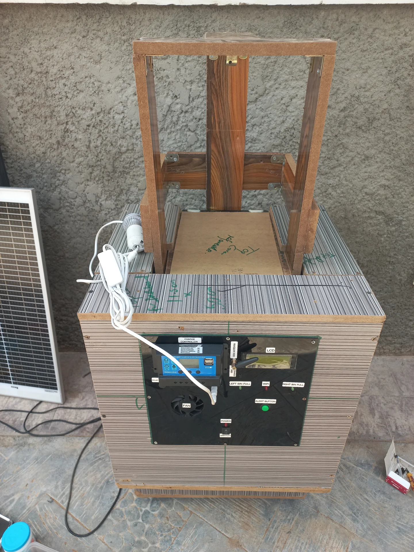
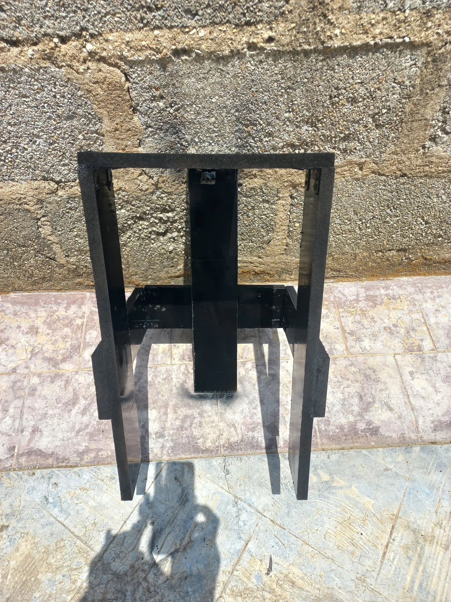
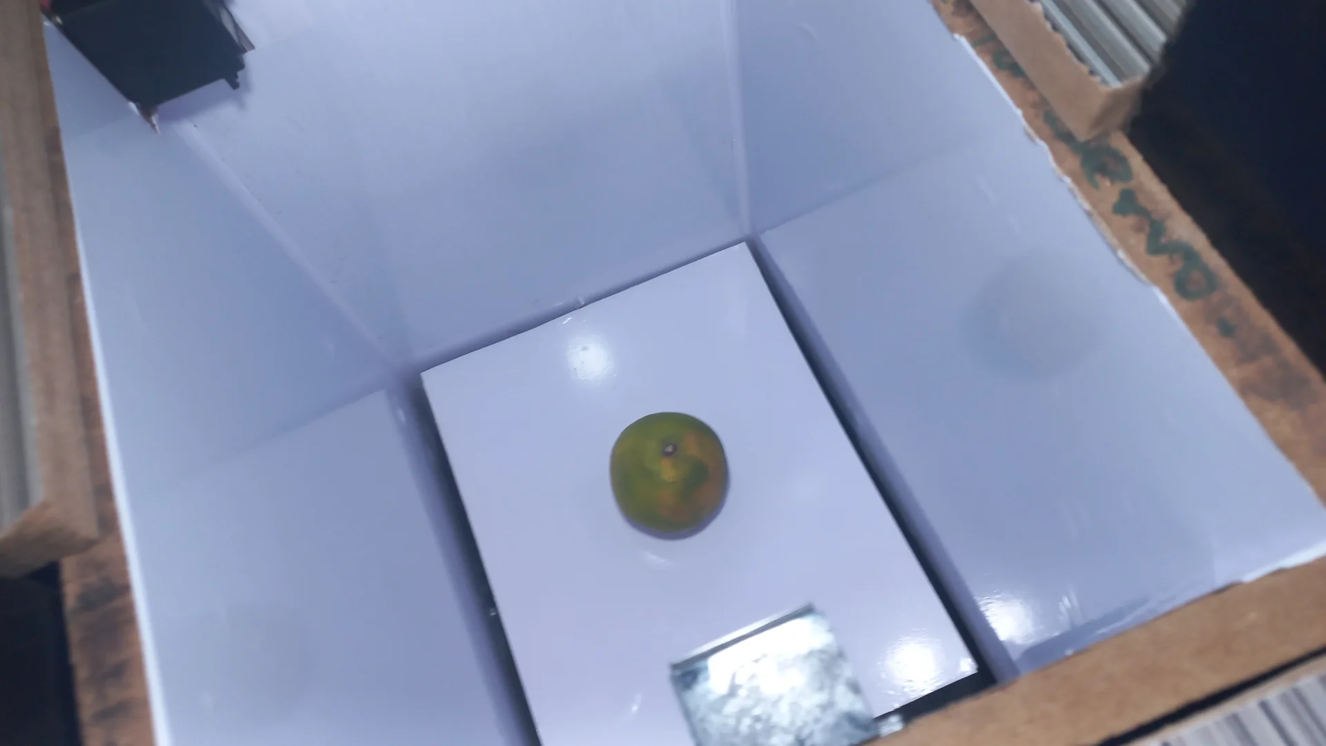
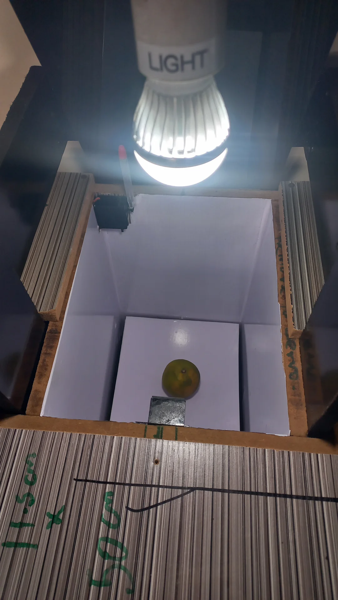
Full build documentation from component procurement to the completed, live-running system.


YouTube Demo, coming soon
A full walk-through of the AI classification pipeline and live sorting system will be uploaded to YouTube.
I sincerely appreciate you taking the time to explore my portfolio and learn about my work and expertise. If you have any questions or wish to discuss potential collaborations, please feel free to reach out via the Contact section.
Best regards,
Damilare Lekan, Adekeye.