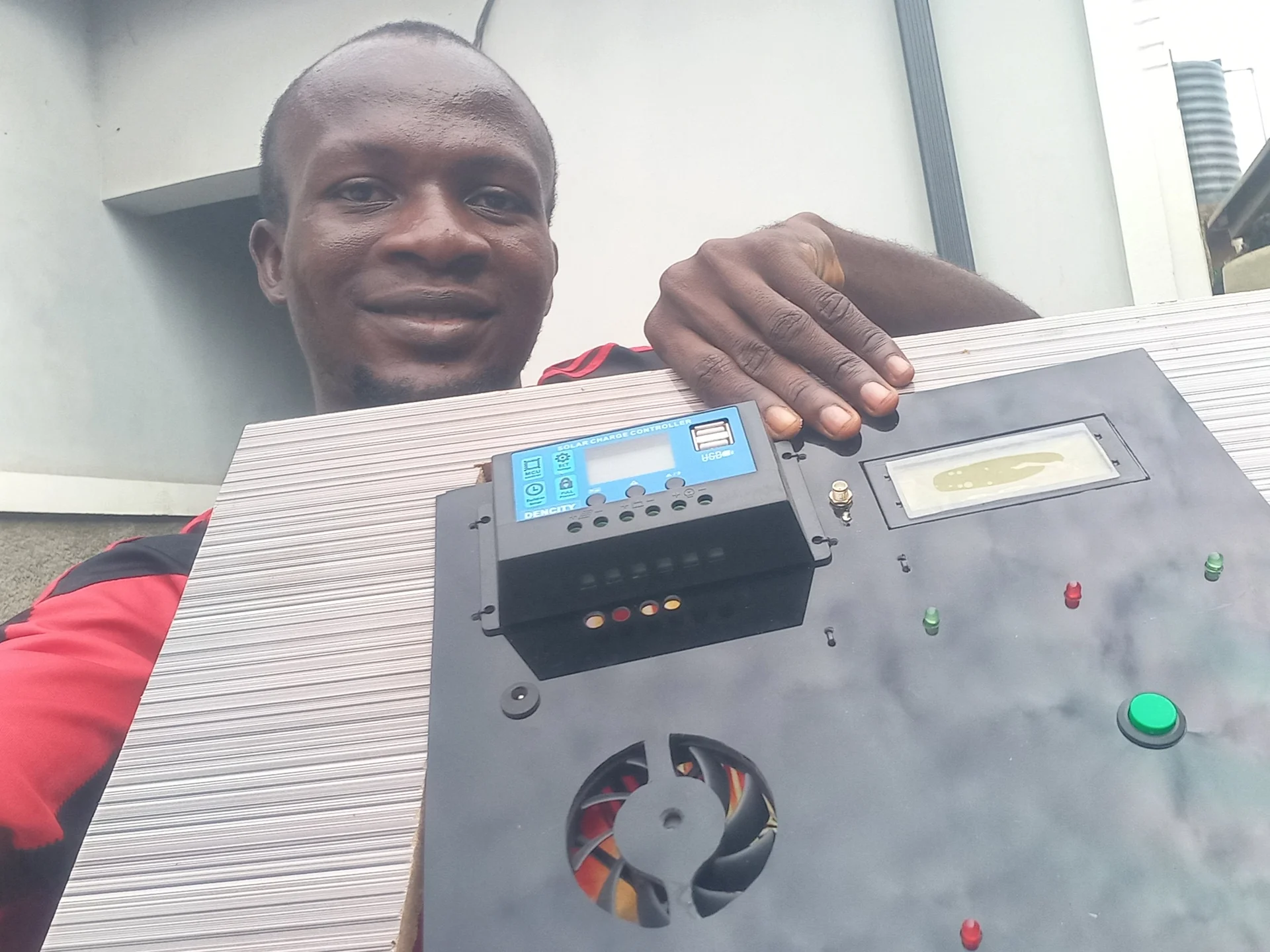
ESP32 Hardware Controller: Servo Sorting, Ultrasonic Fill-Level Sensing, SIM800L GSM Alerts, and UART Bridge to Raspberry Pi 5 AI Engine
This project automates household or institutional waste segregation using a two-processor architecture: a Raspberry Pi 5 handles AI-based camera classification using a YOLO11n NCNN model, while the ESP32 manages all real-time hardware control: servo actuation, ultrasonic bin sensing, GSM alerts, and LCD feedback. The two processors communicate over a UART serial link at 115200 baud.
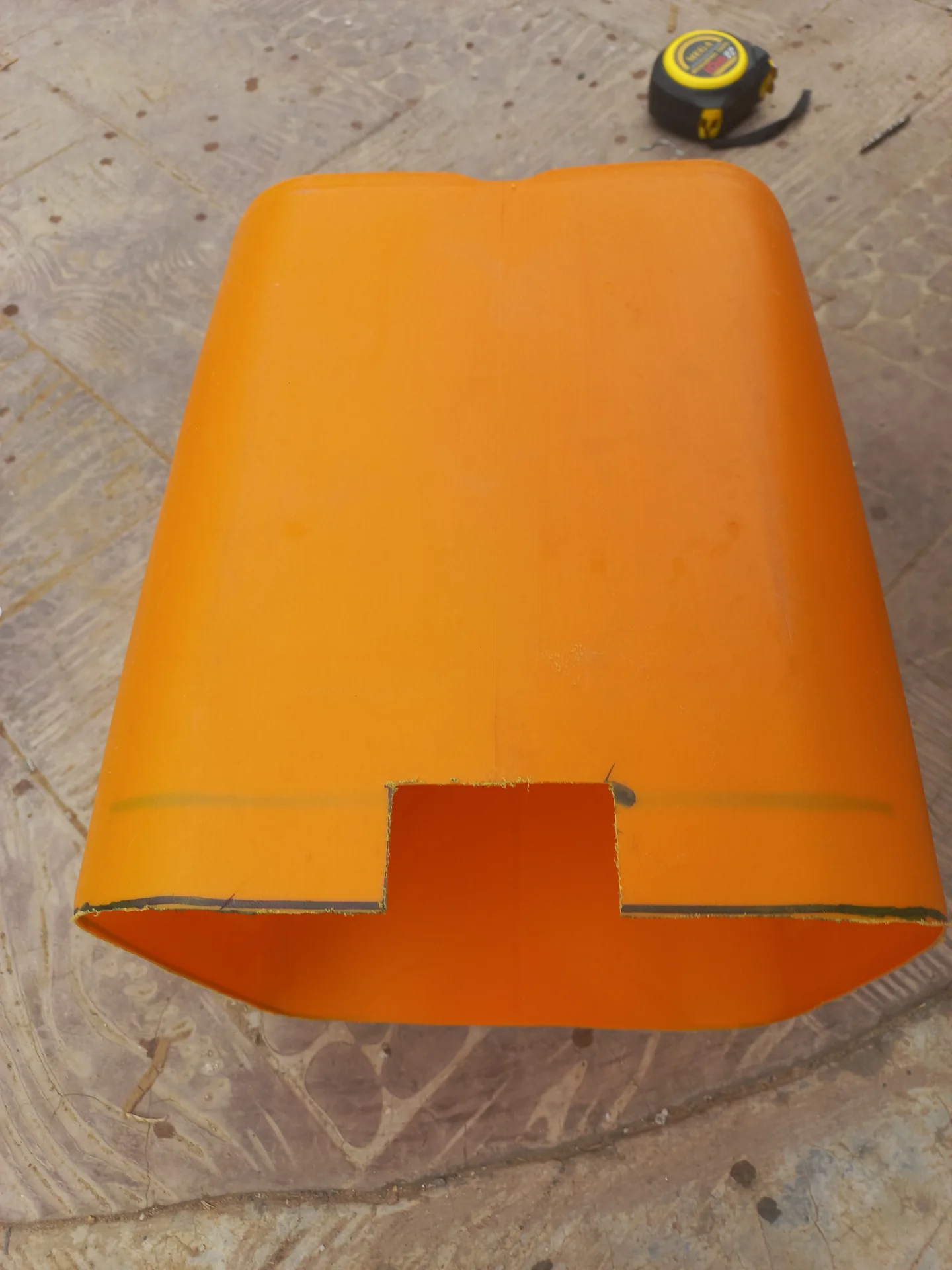
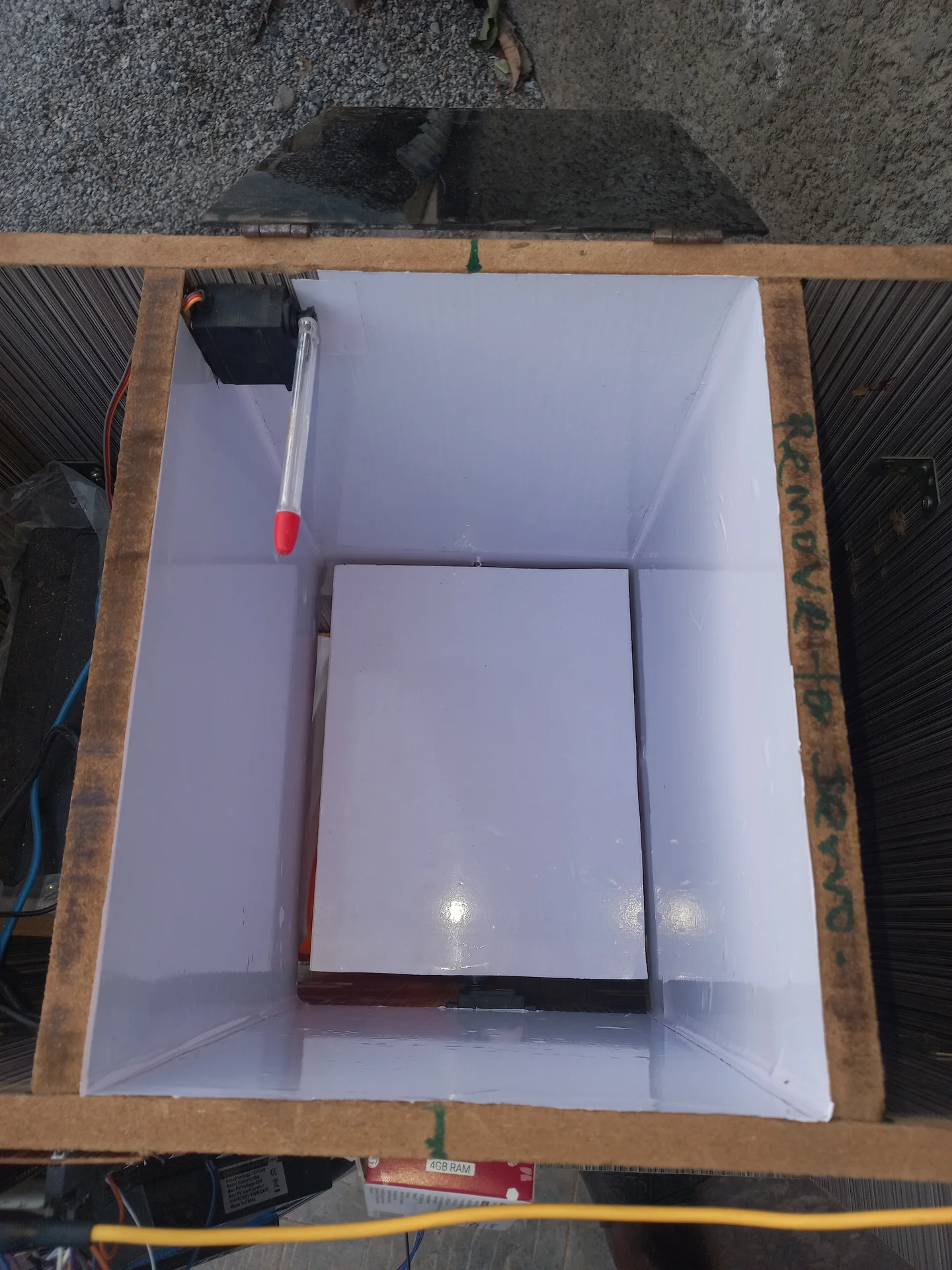
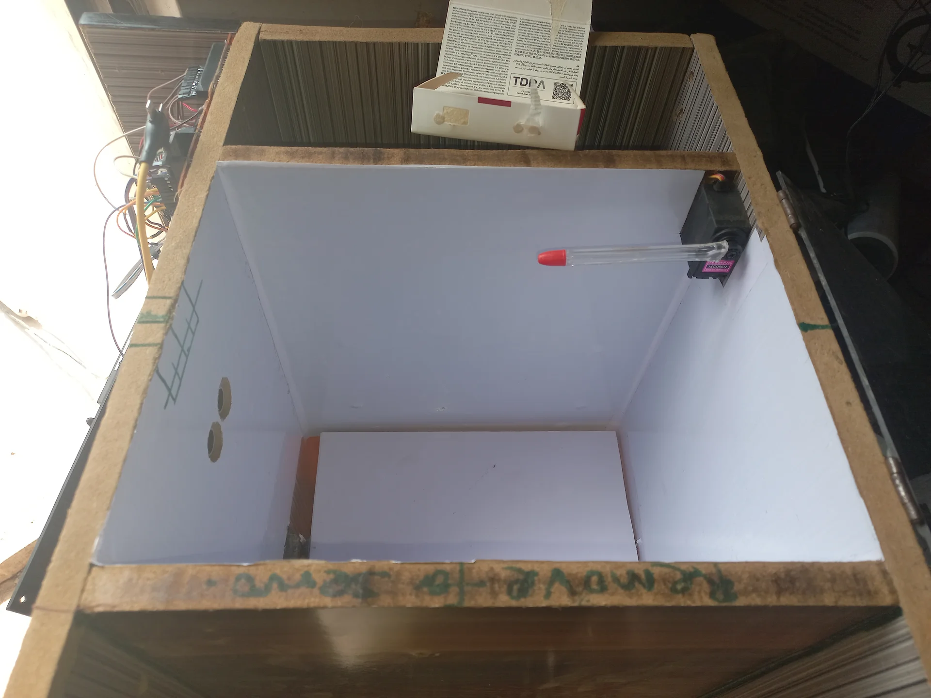
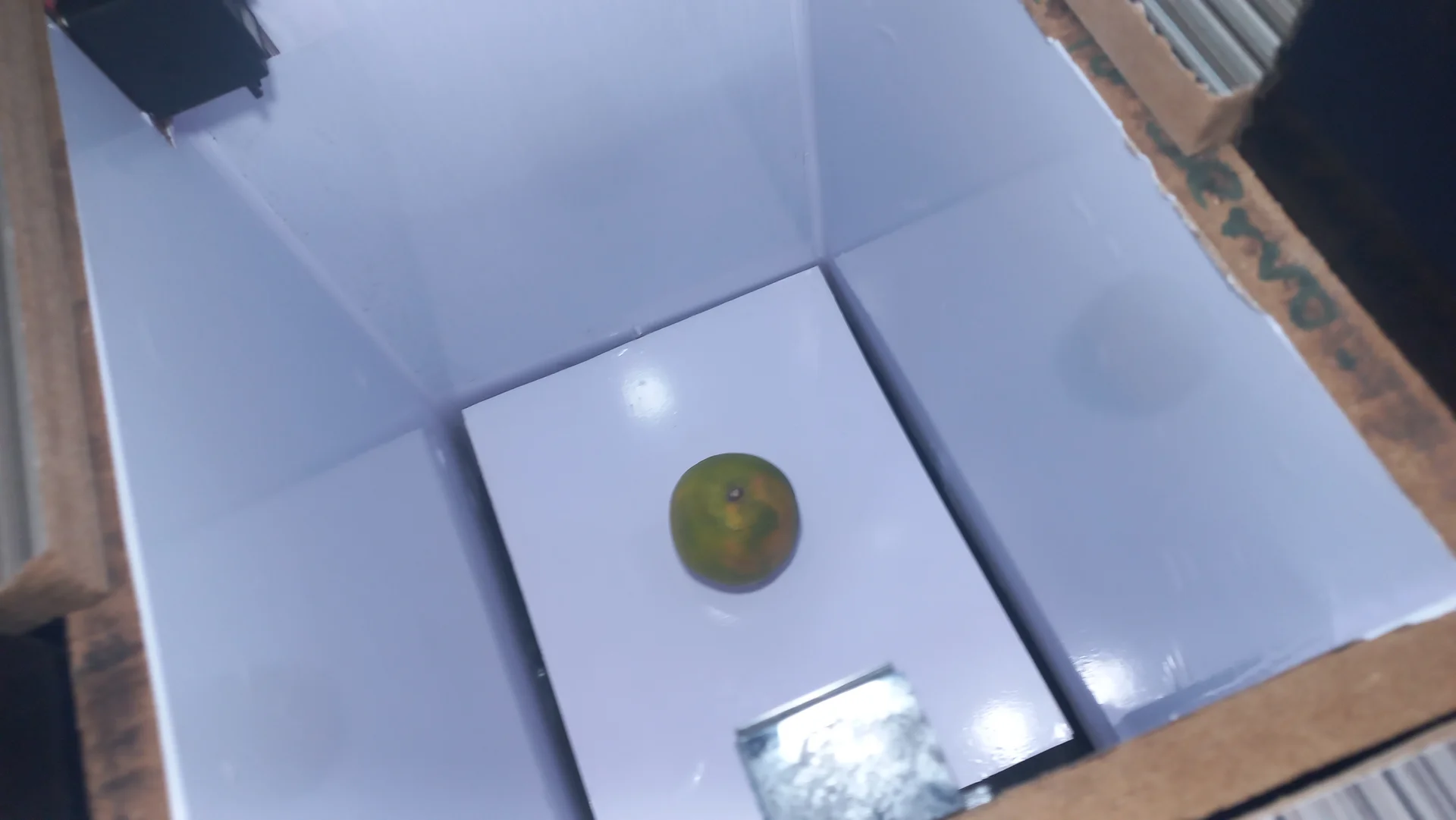
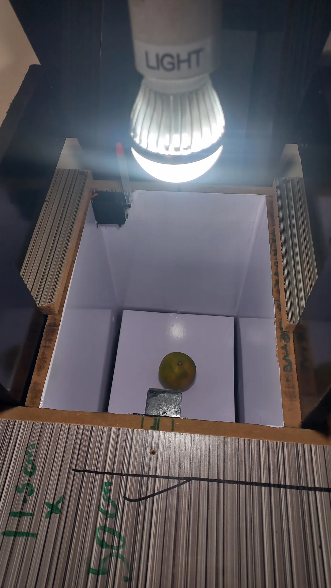
When a user drops an item into the deposit compartment, an ultrasonic sensor detects the object and
triggers a 5-second settle window. After settlement, the ESP32 sends a SCAN command to
the Pi. The Pi captures a frame, runs YOLO11n inference, votes across multiple frames over 5
seconds, then replies with R (Recyclable) or N (Non-Recyclable). The
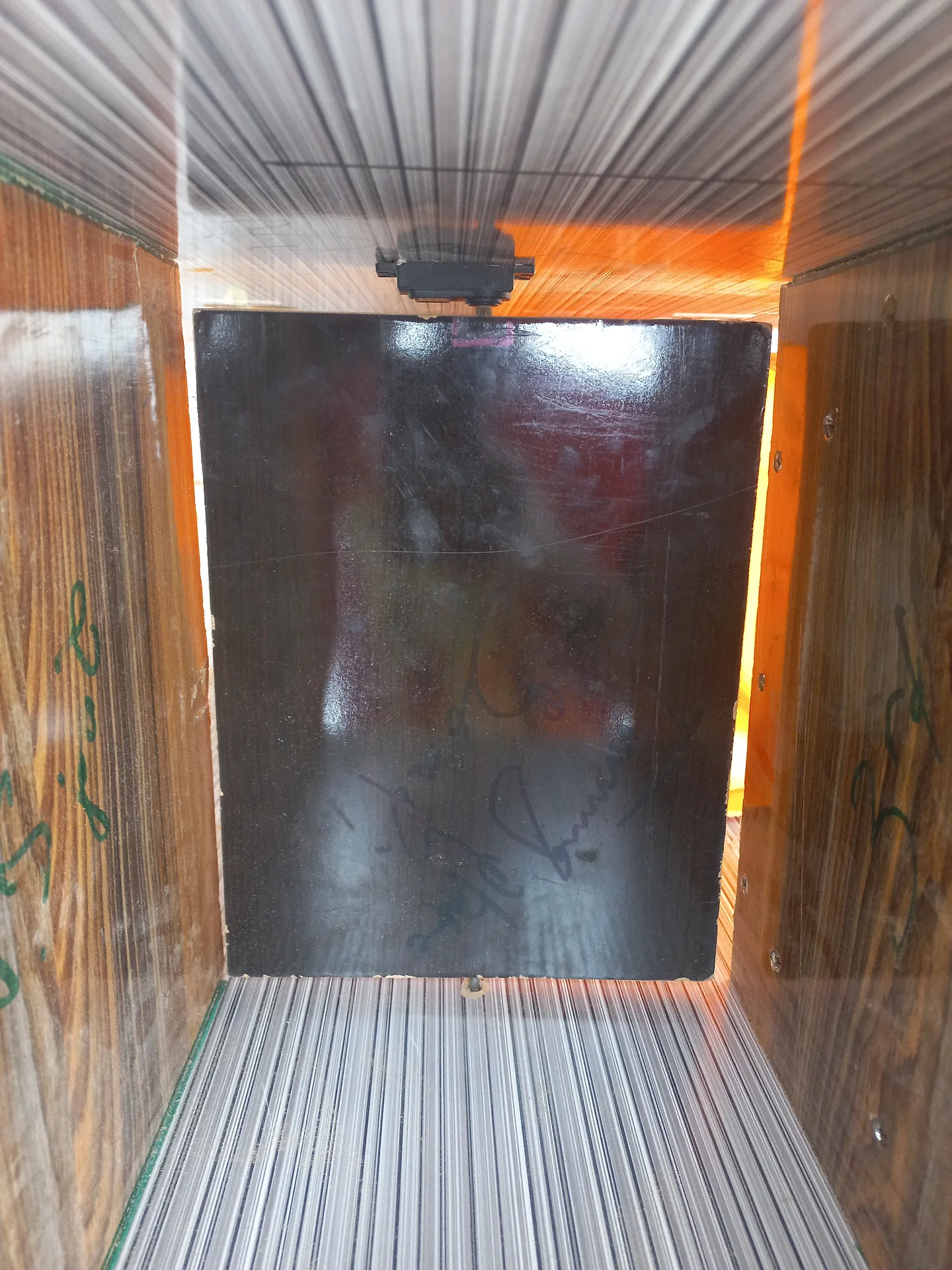
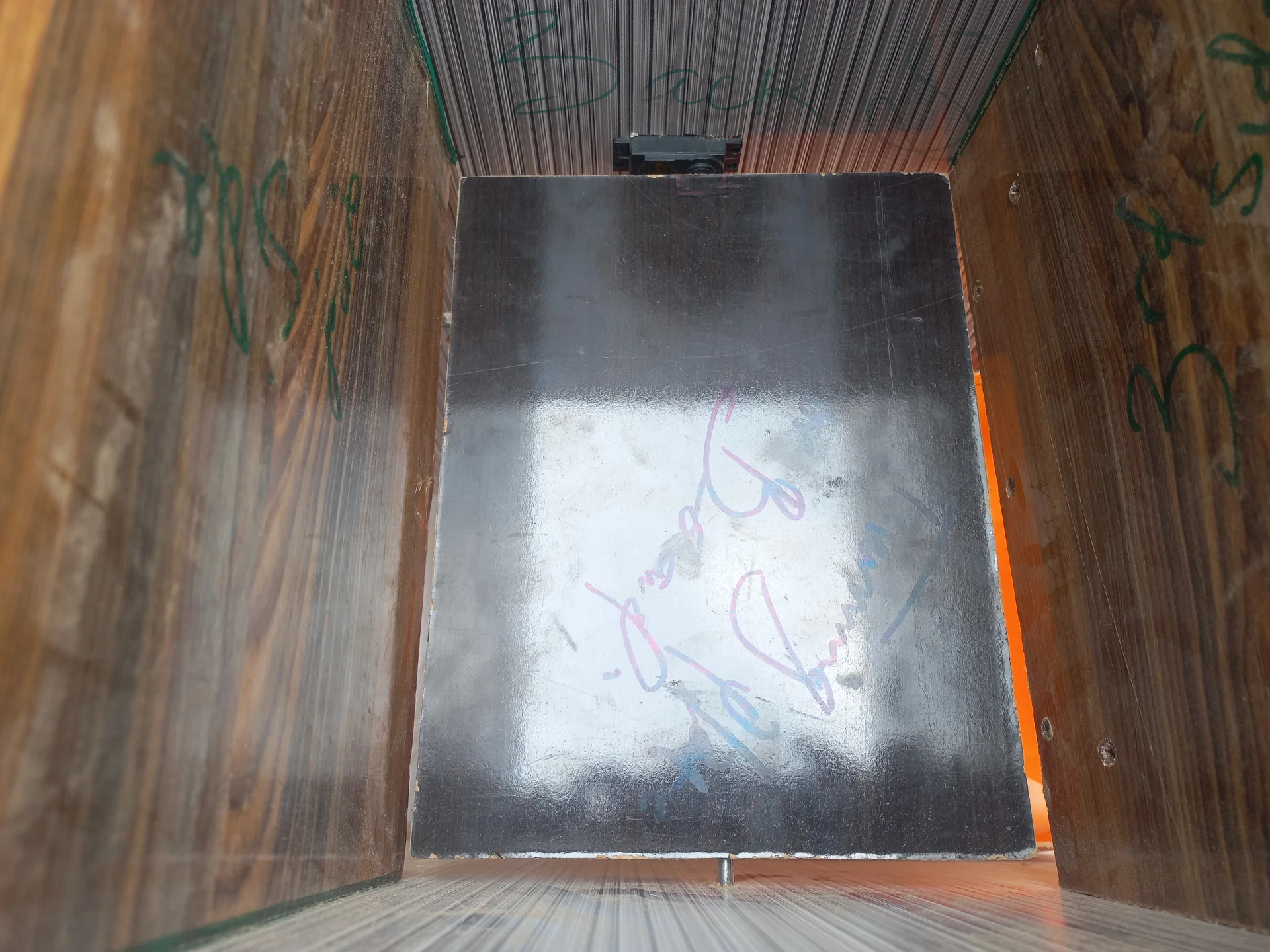
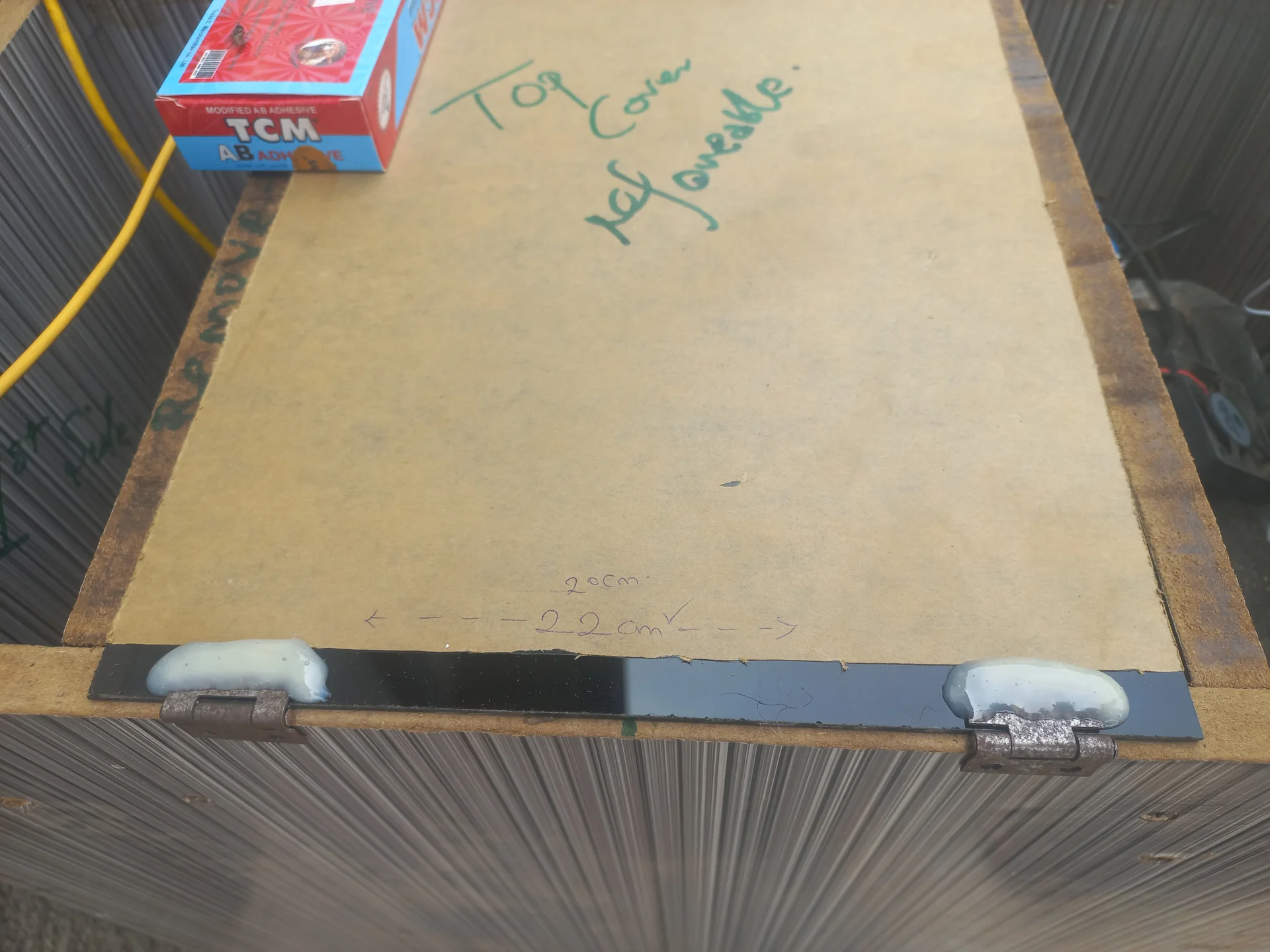
ESP32 opens the cover hatch and pivots the sorting platform to direct the item into the correct bin.
Fill levels are monitored continuously, and an SMS is sent when either bin is full.
moveAndDetach() holds position with
blocking delay() then detaches PWM signal, eliminating servo buzz in the resting
position.READY\n). It stays
open during normal sorting operation. It closes only when a bin is confirmed full,
preventing any deposit into a full bin. The push-button reset re-opens the cover
after the bin has been emptied and the alert acknowledged.millis() timers; the loop never calls delay() except inside servo
actuation.
The two processors divide responsibilities cleanly along a hardware/software boundary:
The full classification pipeline from deposit to sorted waste takes approximately 12–18 seconds: 5 s settle + 5 s Pi voting + ~2 s servo actuation + 10 s cooldown before the next deposit is accepted.
| Component | Quantity | Role |
|---|---|---|
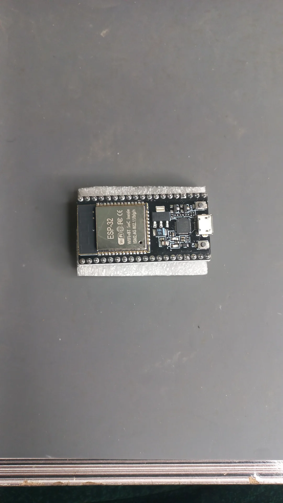
| ESP32 DevKit | 1× | Main microcontroller, all real-time hardware control |
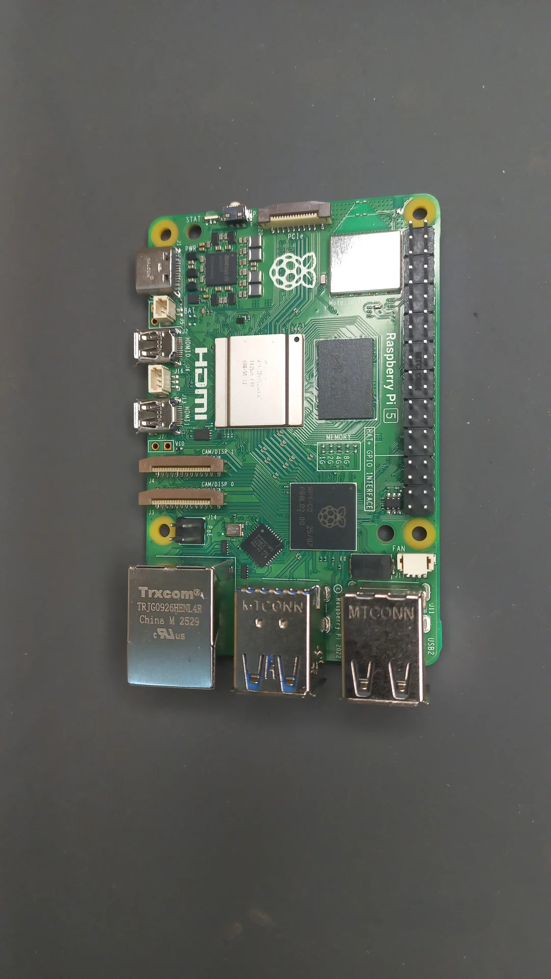
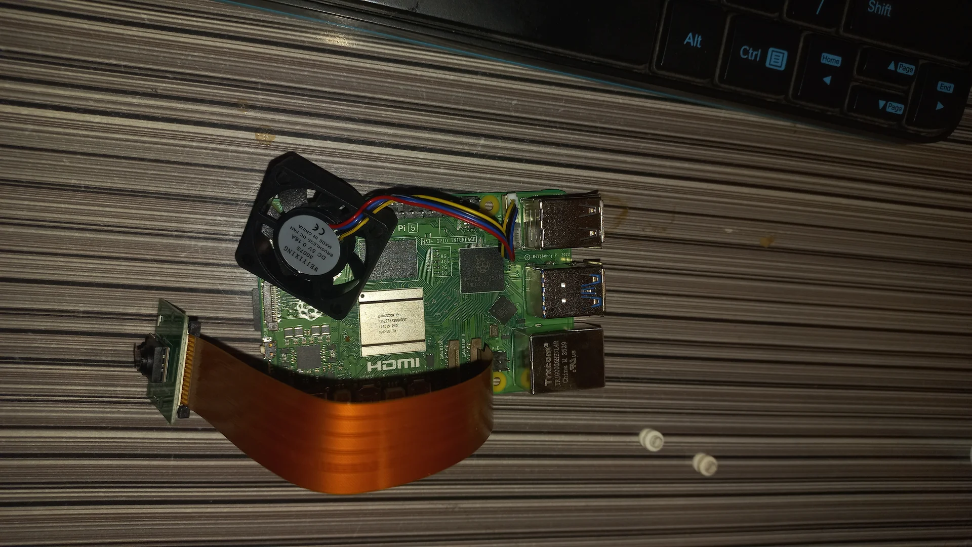
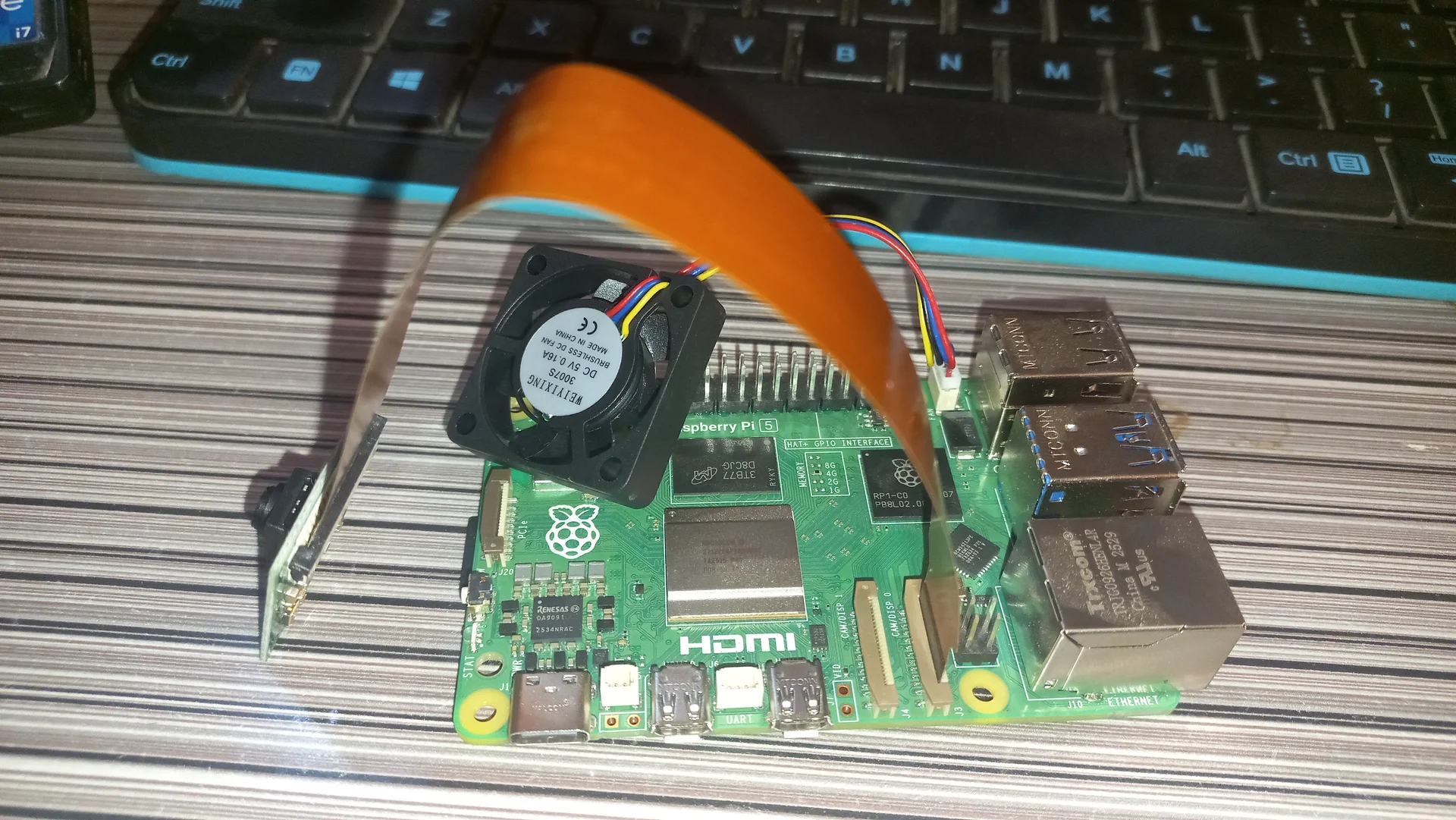
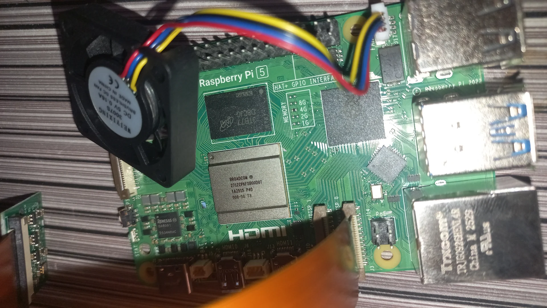
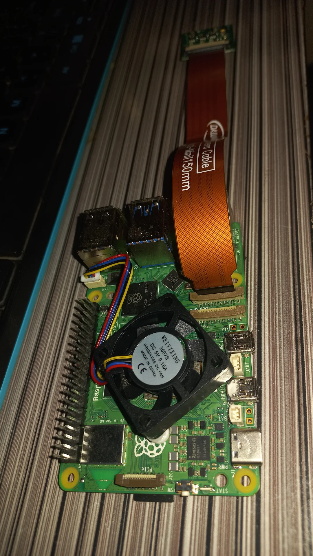
| Raspberry Pi 5 (4 GB) | 1× | AI inference engine: YOLO11n NCNN (see SBC page) |
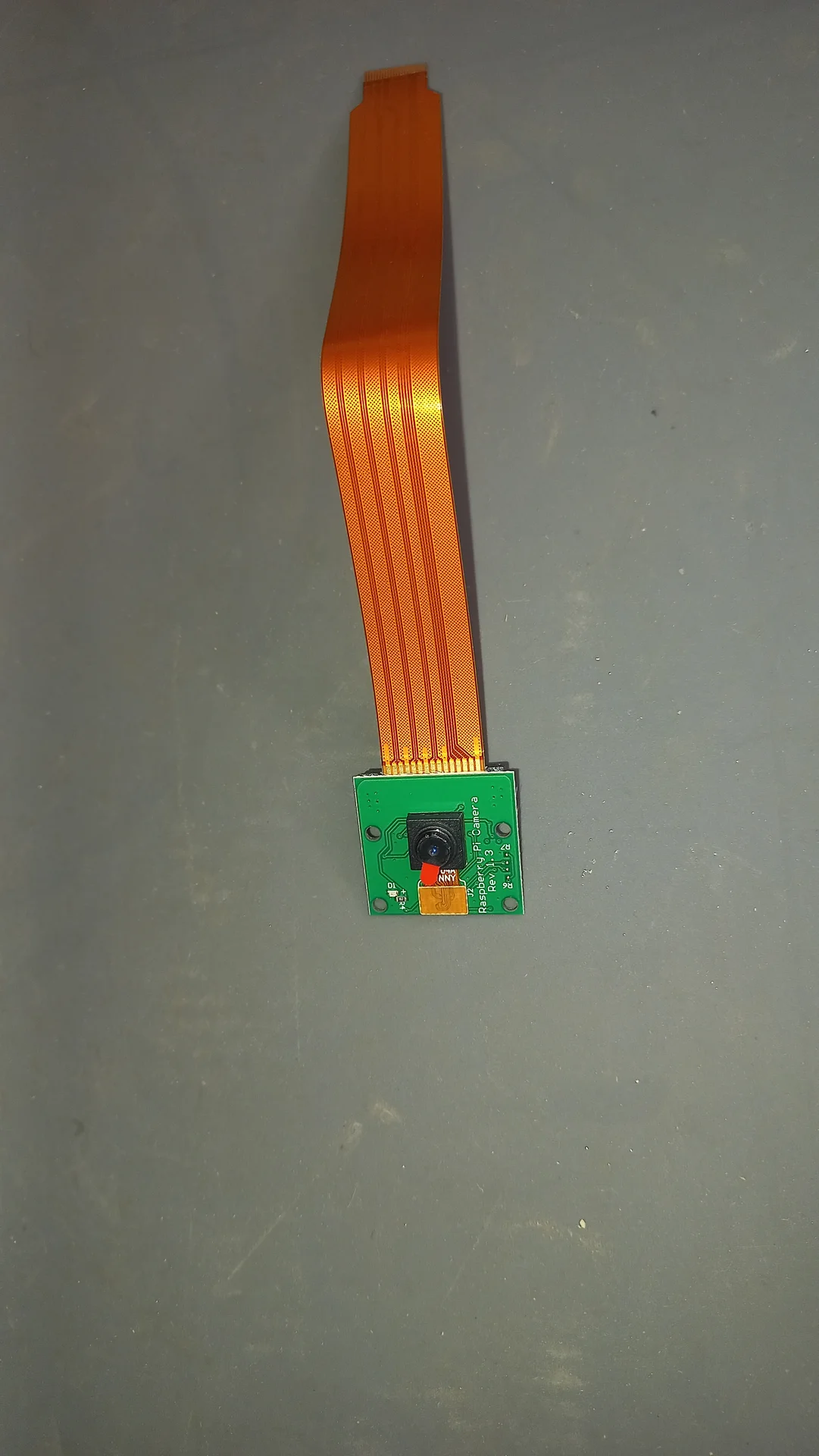
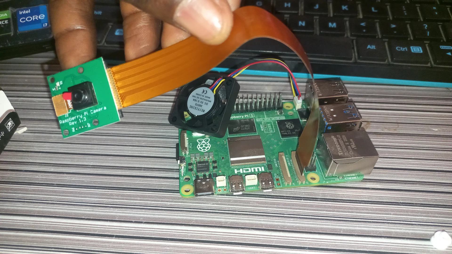
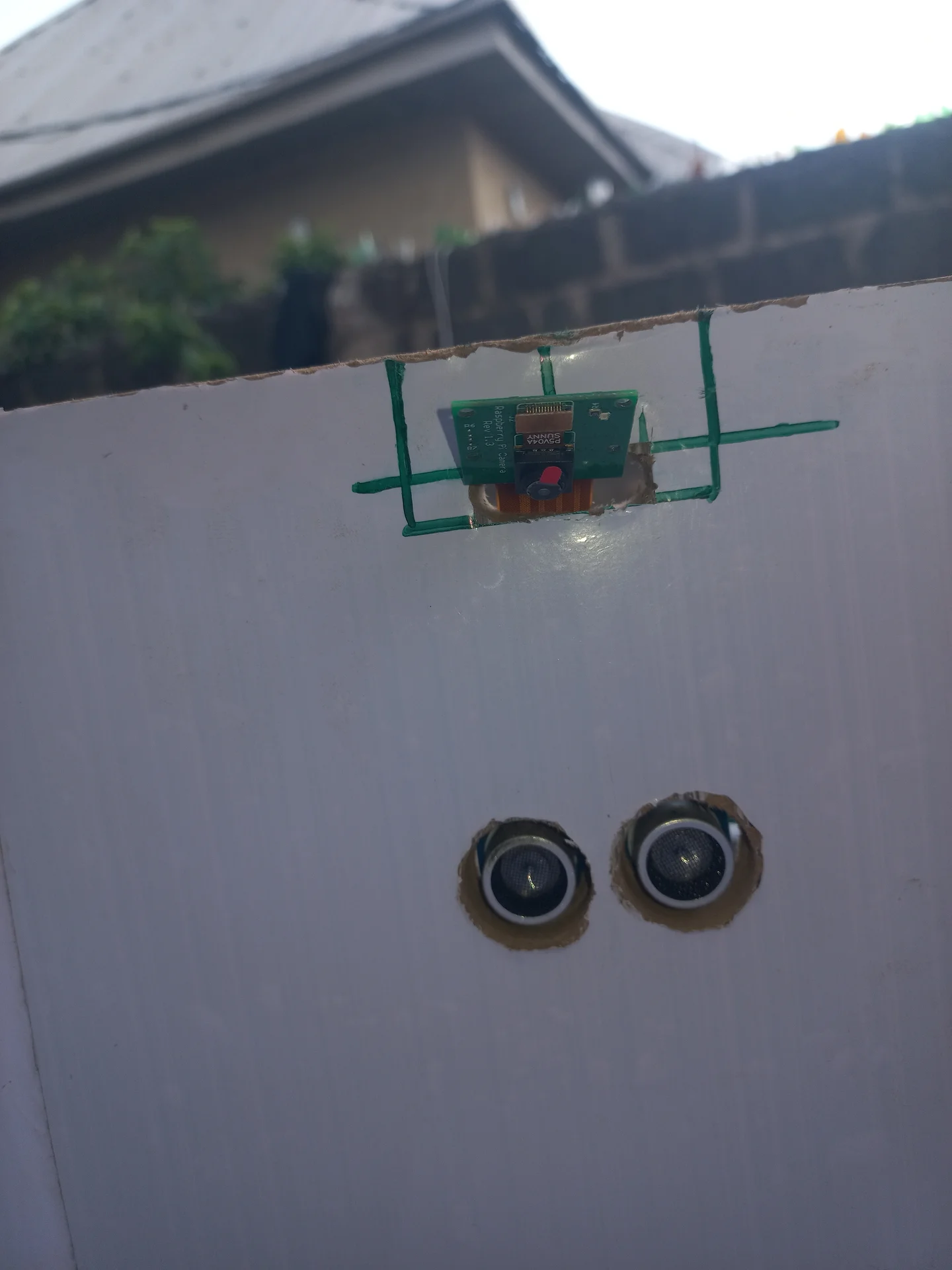
| Pi Camera Module v2 | 1× | Image capture for waste classification |
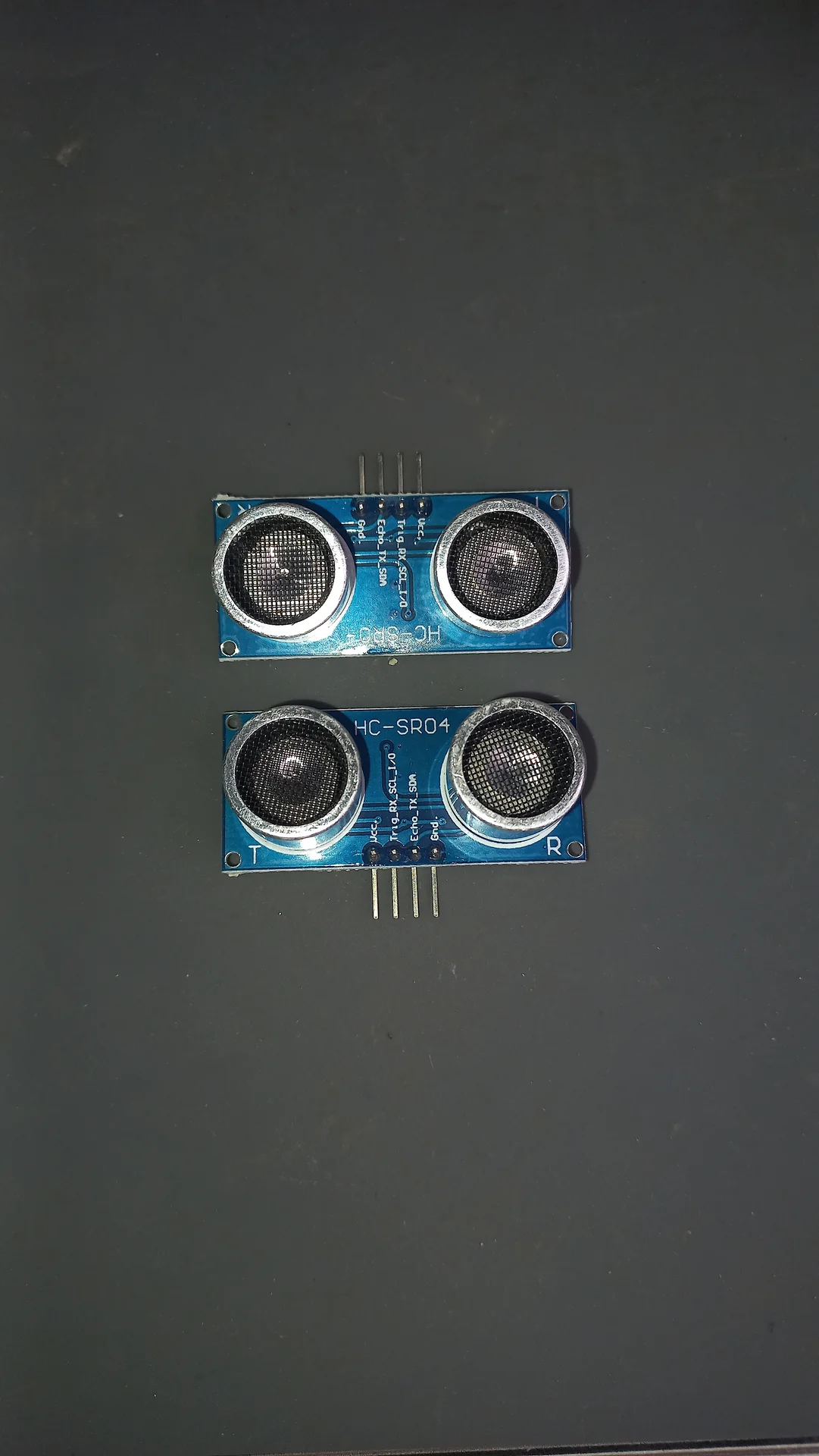
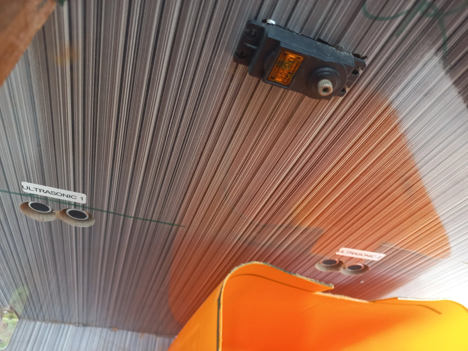
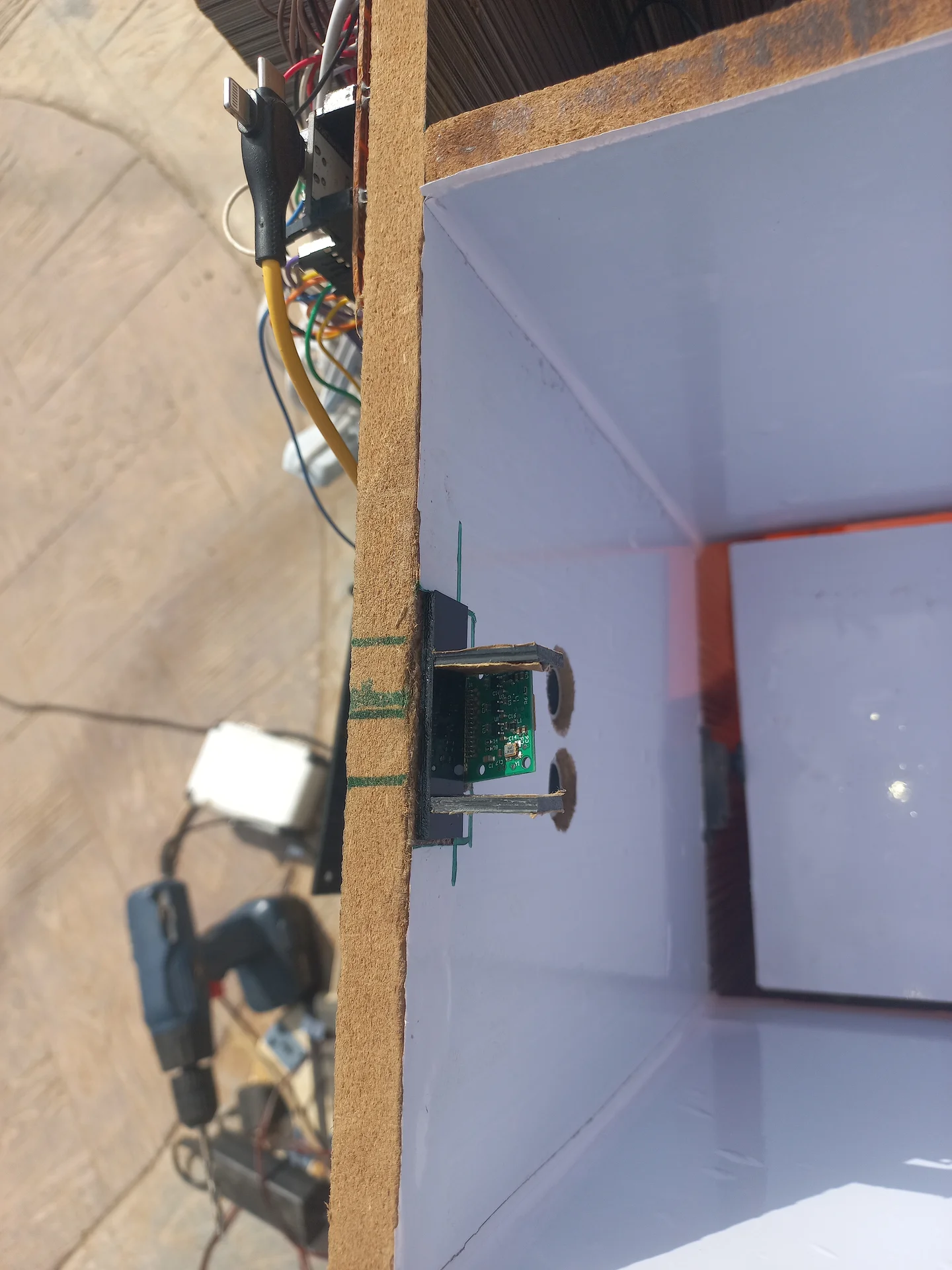
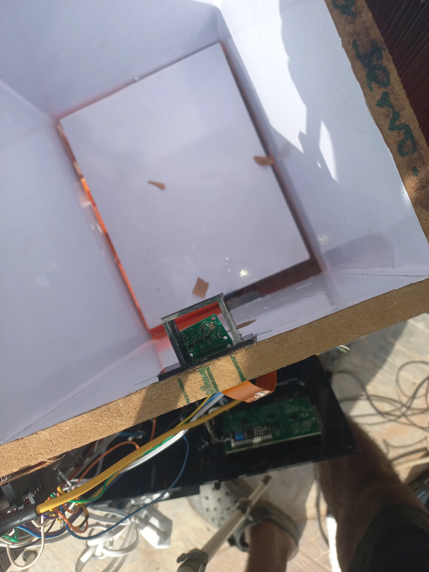
| HC-SR04 Ultrasonic Sensor | 3× | US1: left bin fill, US2: right bin fill, US3: deposit detection |
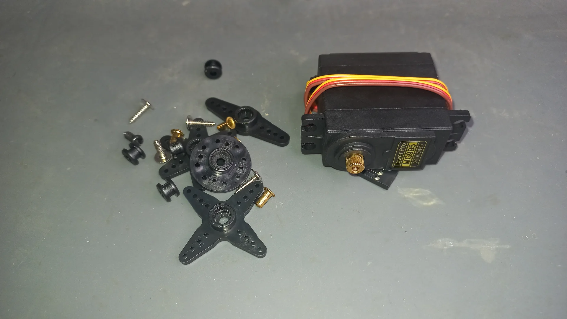
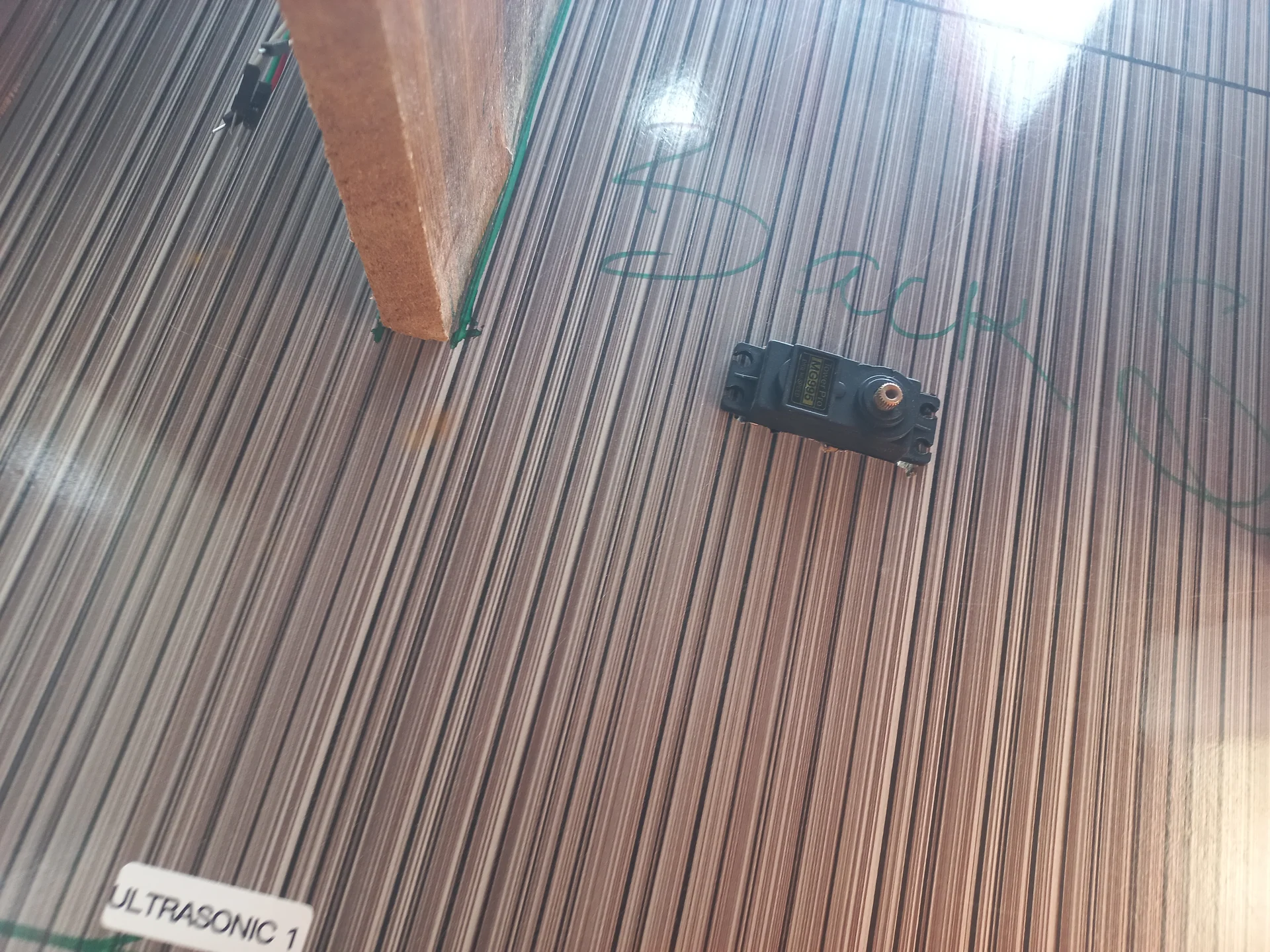
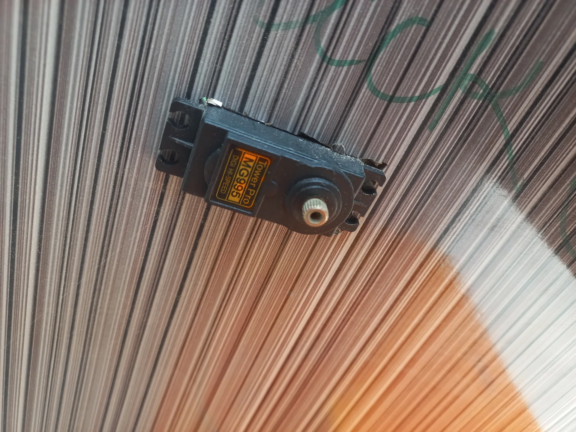
| Servo Motor (SG90 / MG90S) | 2× | Sorting platform pivot + cover hatch open/close |
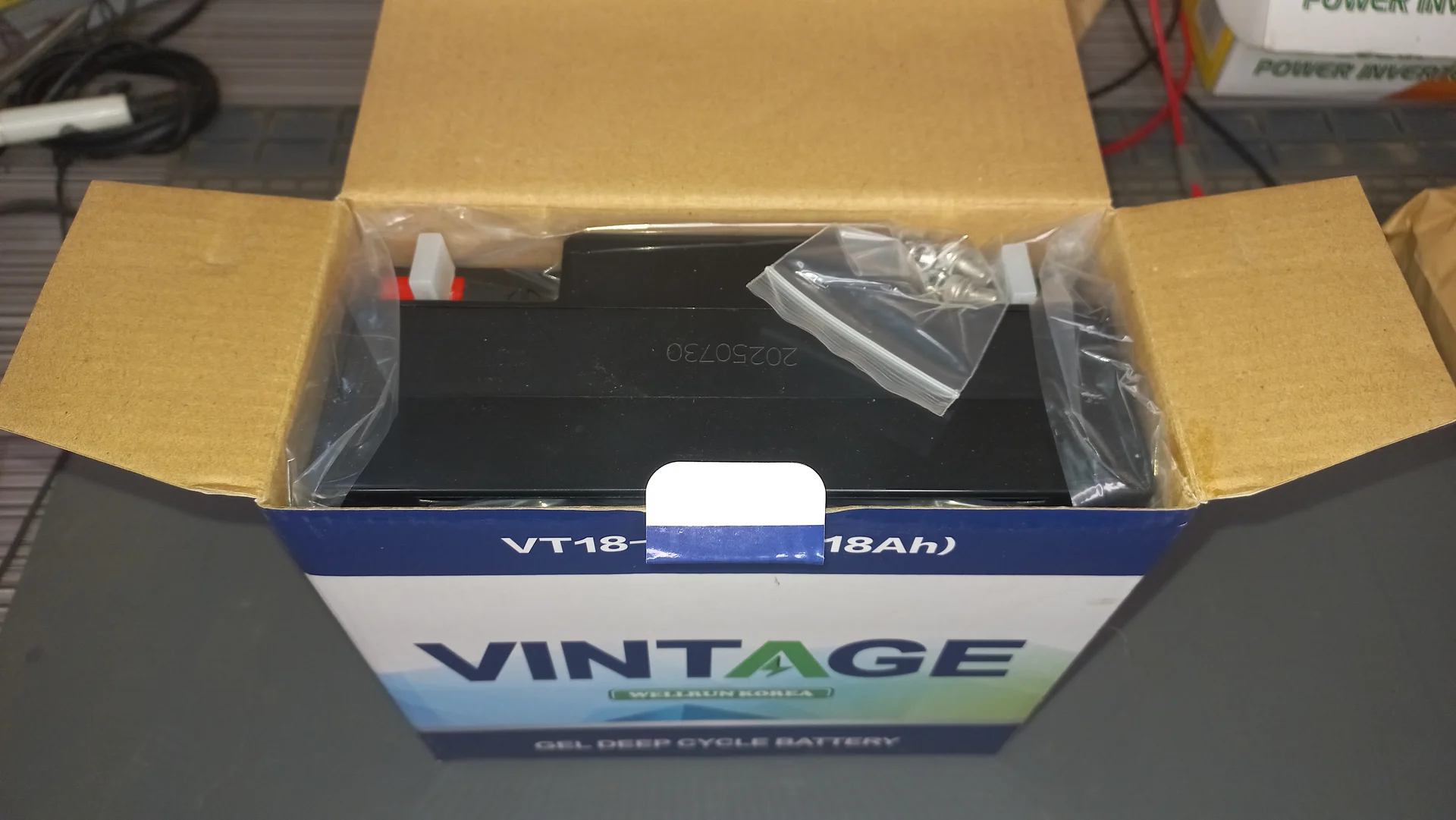
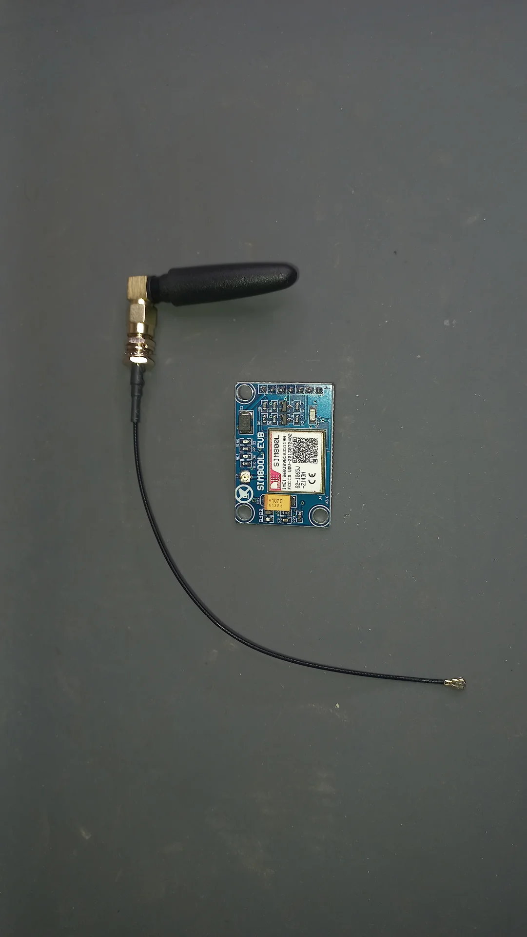
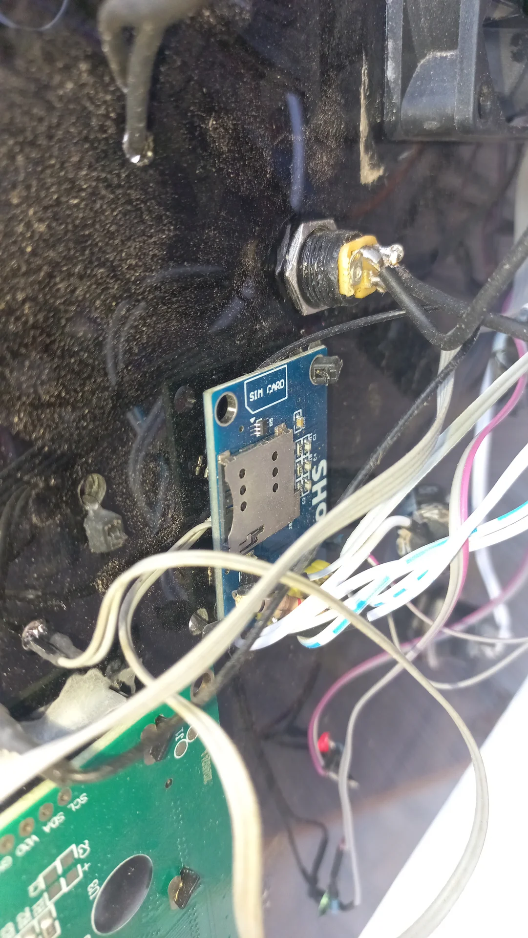
| SIM800L GSM Module | 1× | Sends SMS when bin full |
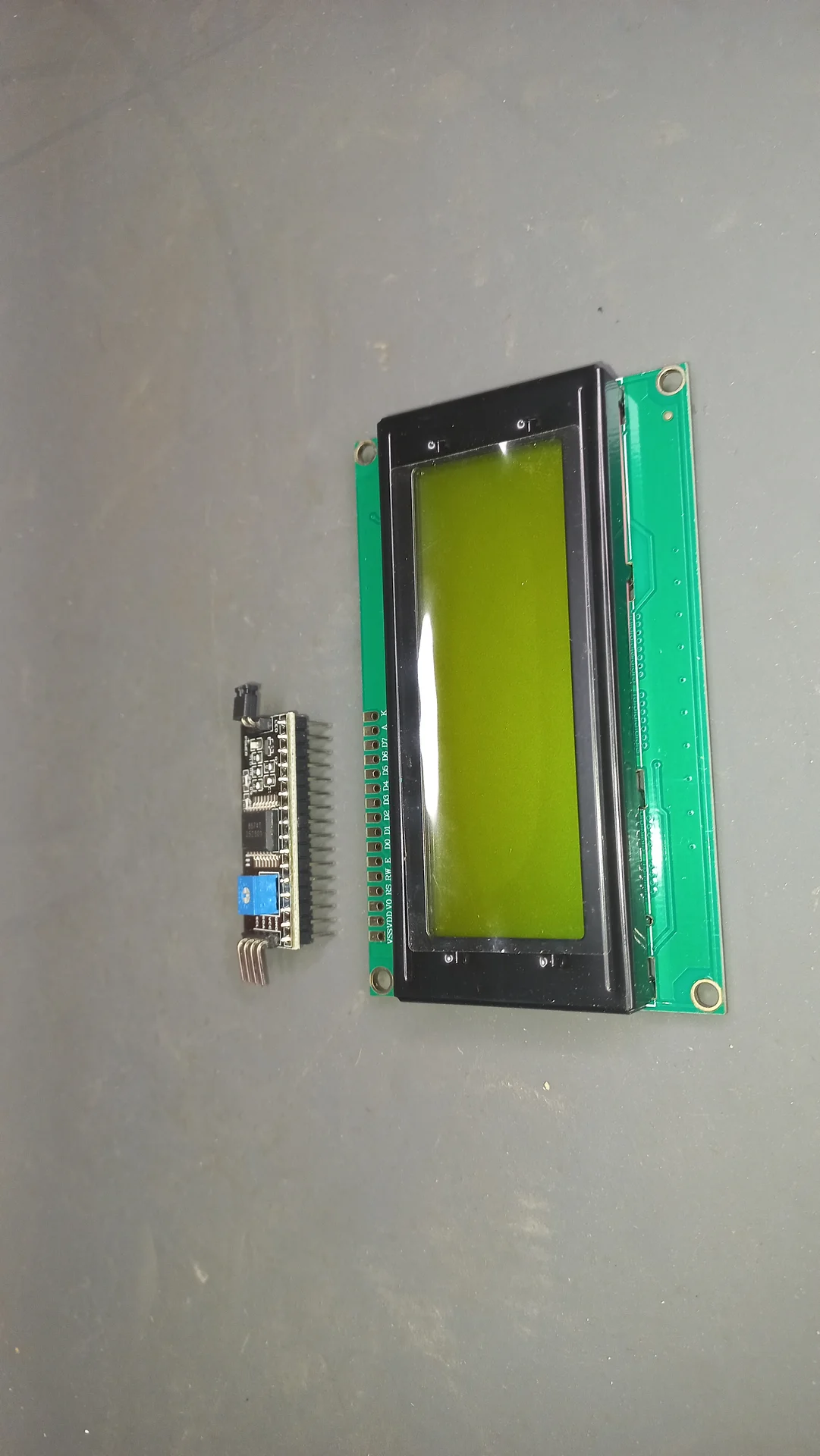
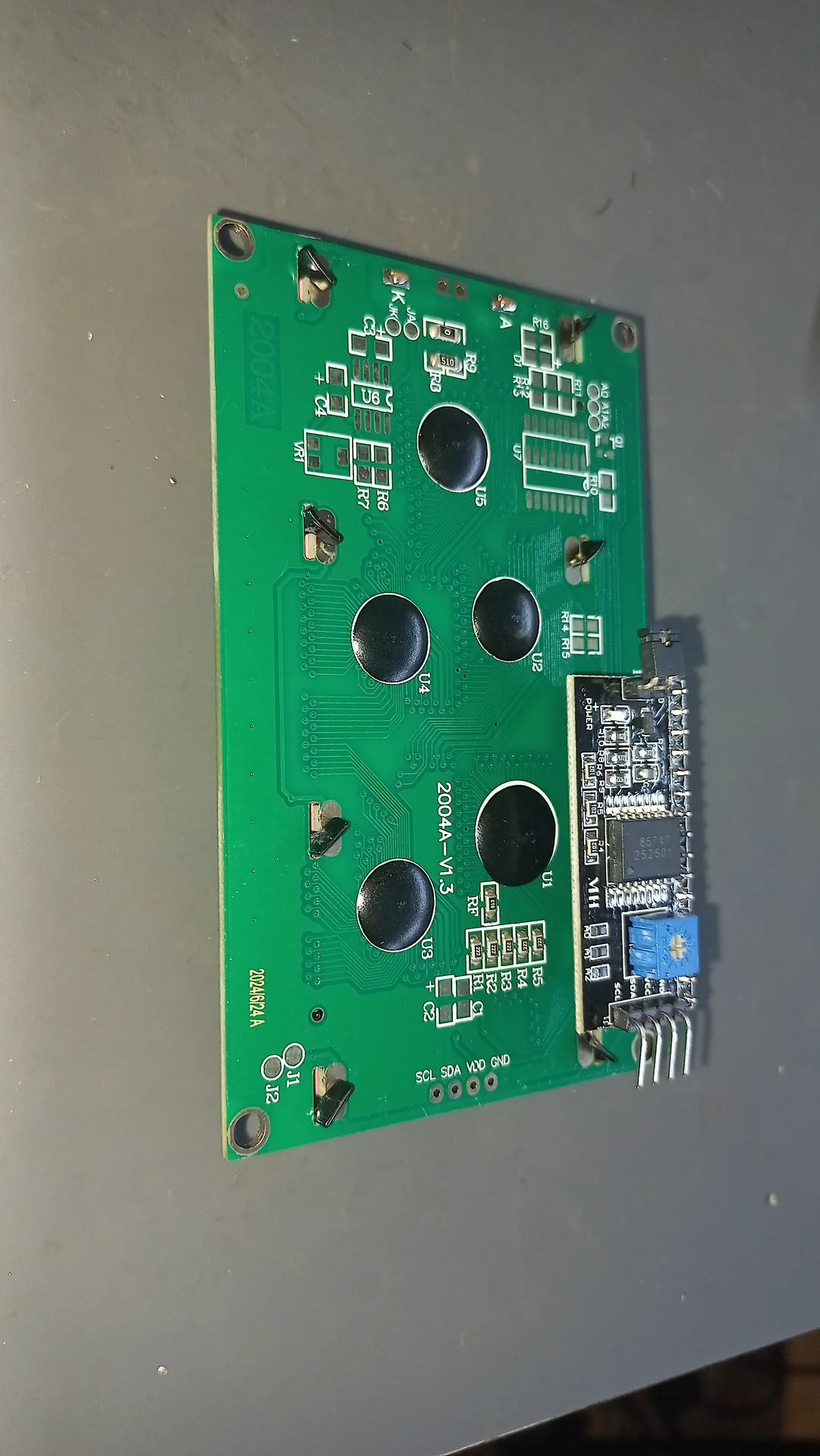
| 20×4 I2C LCD (0x27) | 1× | Live system dashboard |
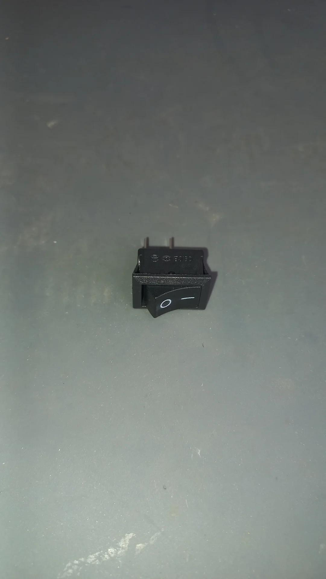
| Passive Buzzer | 1× | Bin-full warning alarm |
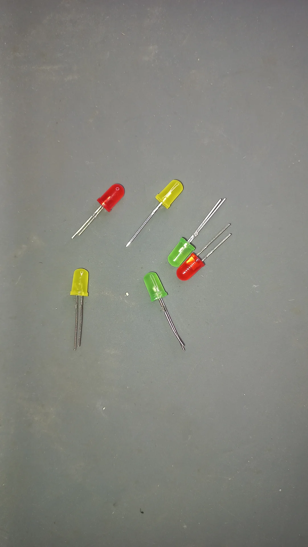
| LED (Red × 2, Yellow × 1) | 3× | Left bin full, right bin full, system-ready indicator |
| Push Button | 1× | Bin-emptied reset / alert acknowledge |
| Sensor | Role | TRIG Pin | ECHO Pin |
|---|---|---|---|
| US1 | Left bin (Recyclable) fill level | GPIO 19 | GPIO 18 |
| US2 | Right bin (Non-Recyclable) fill level | GPIO 0 | GPIO 4 |
| US3 | Deposit compartment, triggers SCAN | GPIO 26 | GPIO 32 |
| Servo | ESP32 Pin | Recyclable Position | Non-Recyclable Position |
|---|---|---|---|
Sorting platform (sortServo) |
GPIO 14 | 0° | 180° |
Cover hatch (coverServo) |
GPIO 27 | Open: 0° ← centre; Close: 90° (default at boot) | |
| Pi 5 Pin | GPIO Function | Wire Colour | → ESP32 Pin |
|---|---|---|---|
| Pin 8 | GPIO 14 (TX) | Yellow | GPIO 16 (RX) |
| Pin 10 | GPIO 15 (RX) | Orange | GPIO 17 (TX) |
| Pin 6 | GND | Black | GND |
| Component | ESP32 Pin(s) |
|---|---|
| SIM800L GSM (RX / TX) | GPIO 25 / GPIO 33 |
| 20×4 I2C LCD (SDA / SCL) | GPIO 21 / GPIO 22 |
| LED, Left bin full (Green) | GPIO 15 |
| LED, Right bin full (Green) | GPIO 23 |
| LED, System / WiFi (Blue) | GPIO 2 |
| Passive Buzzer | GPIO 12 |
| Reset Push Button | GPIO 13 |
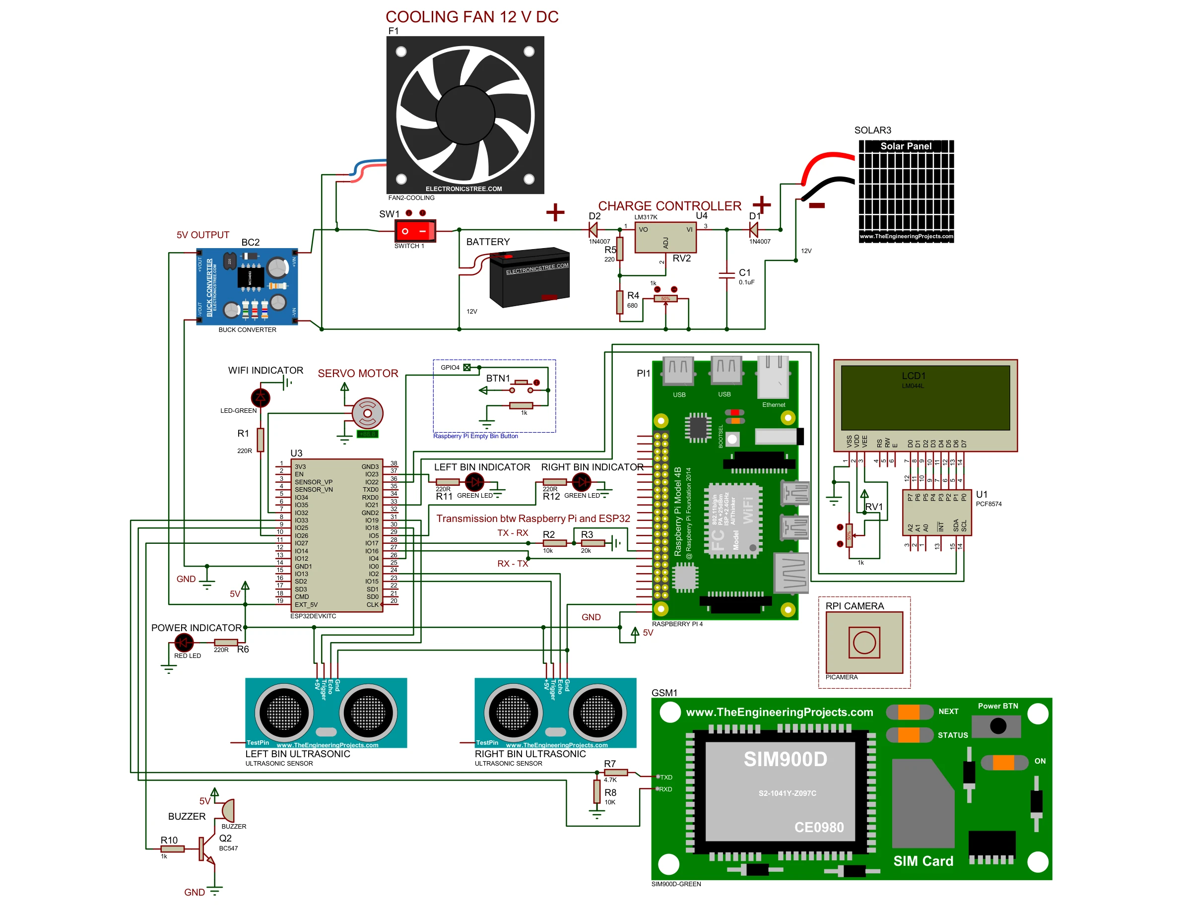
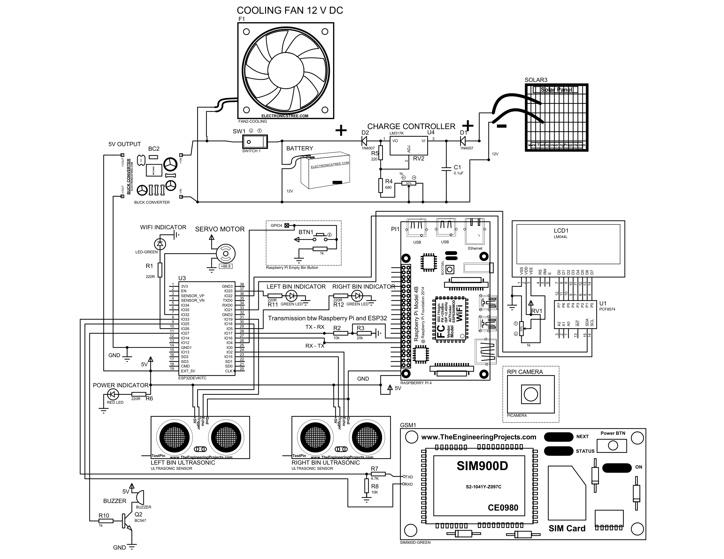
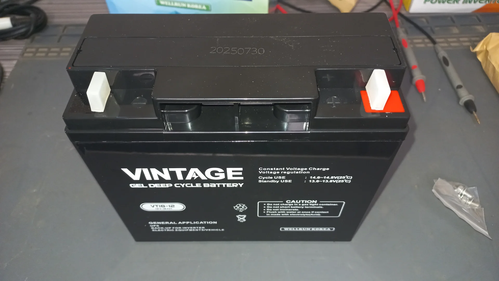
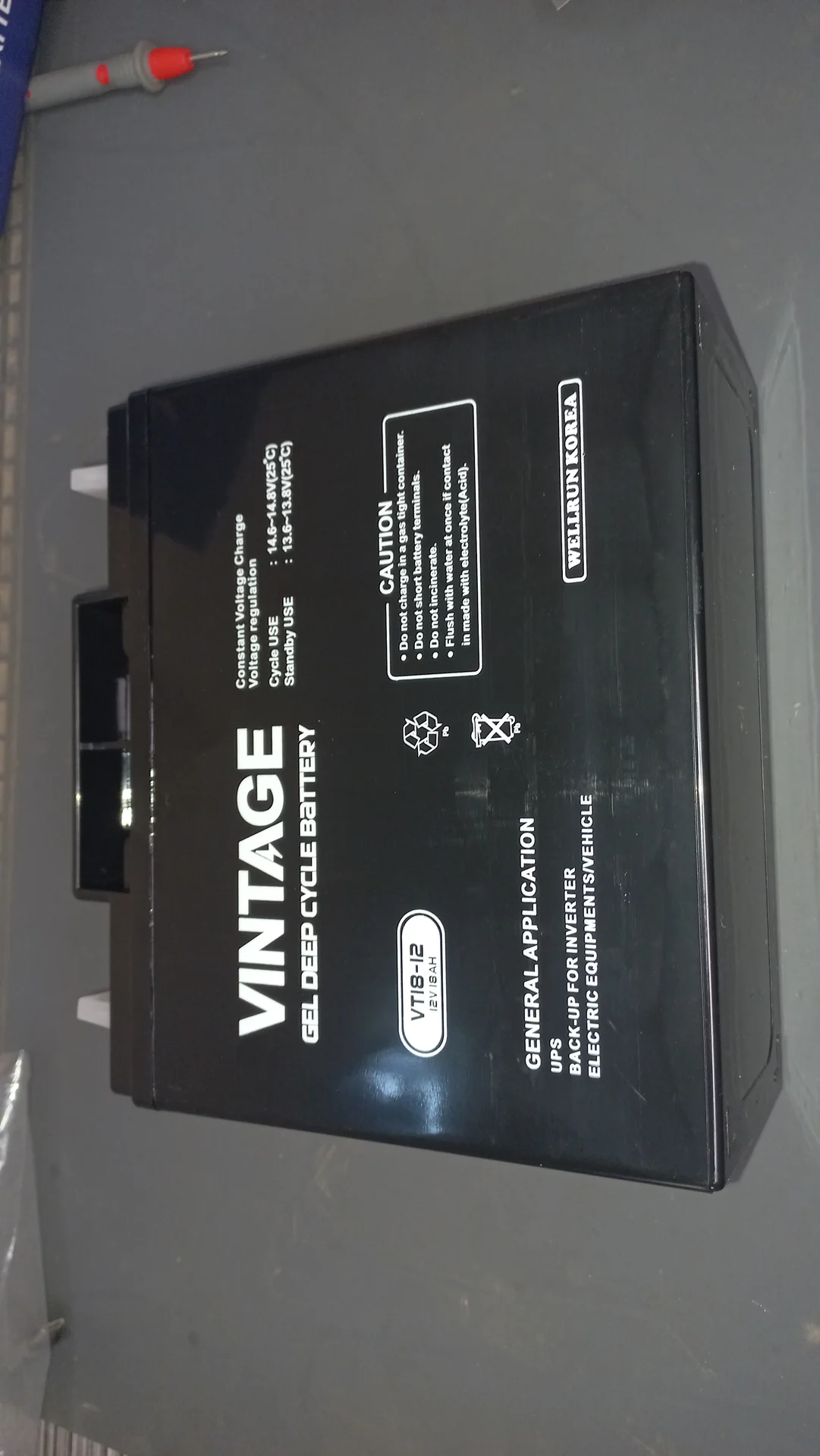
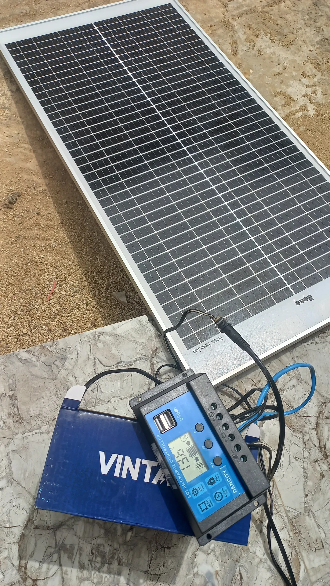
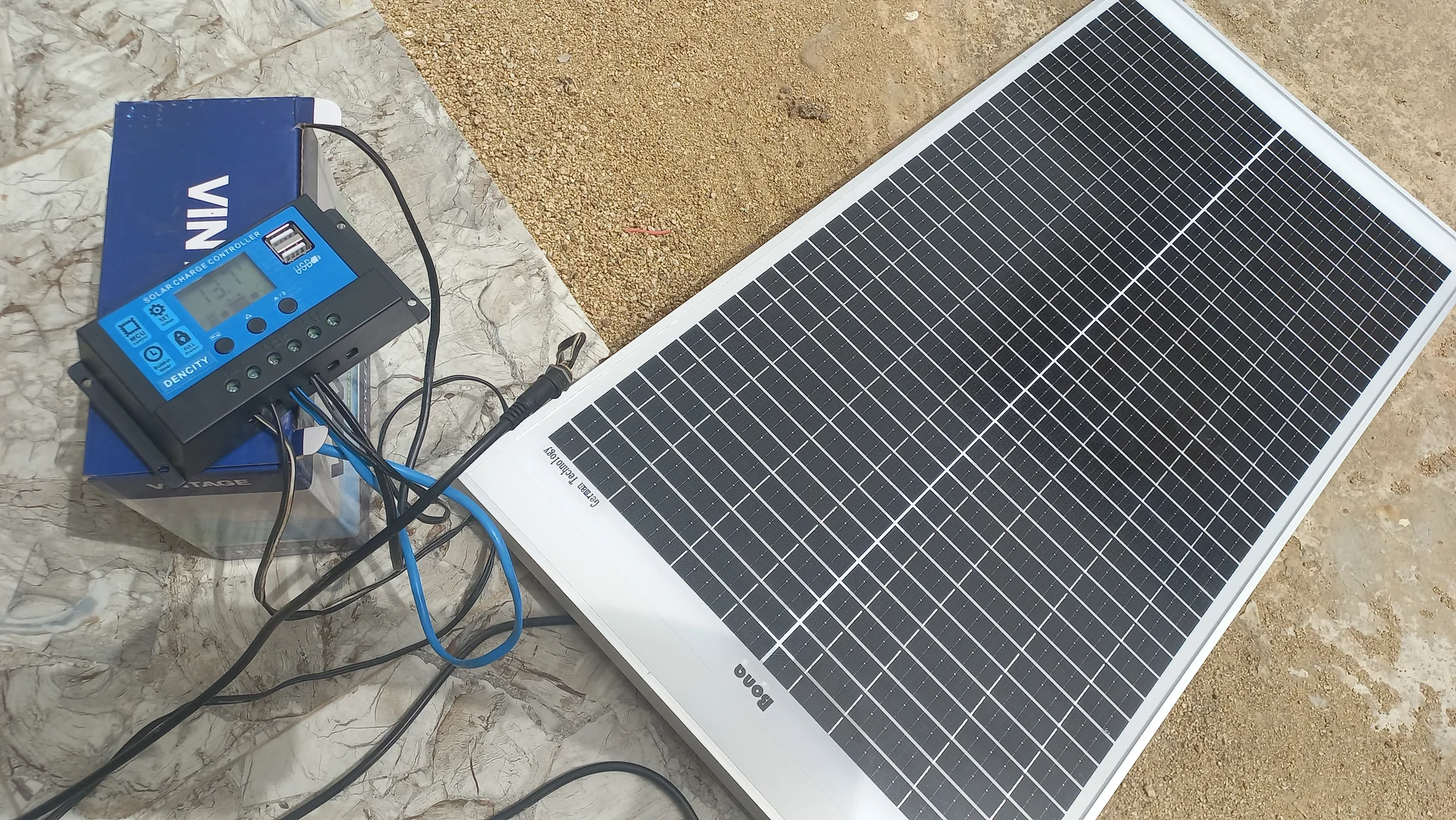
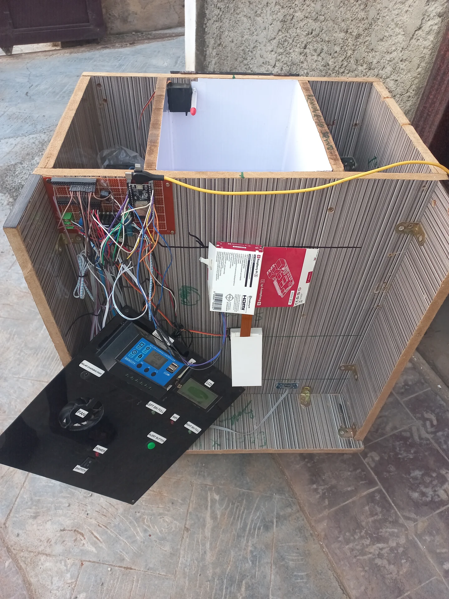
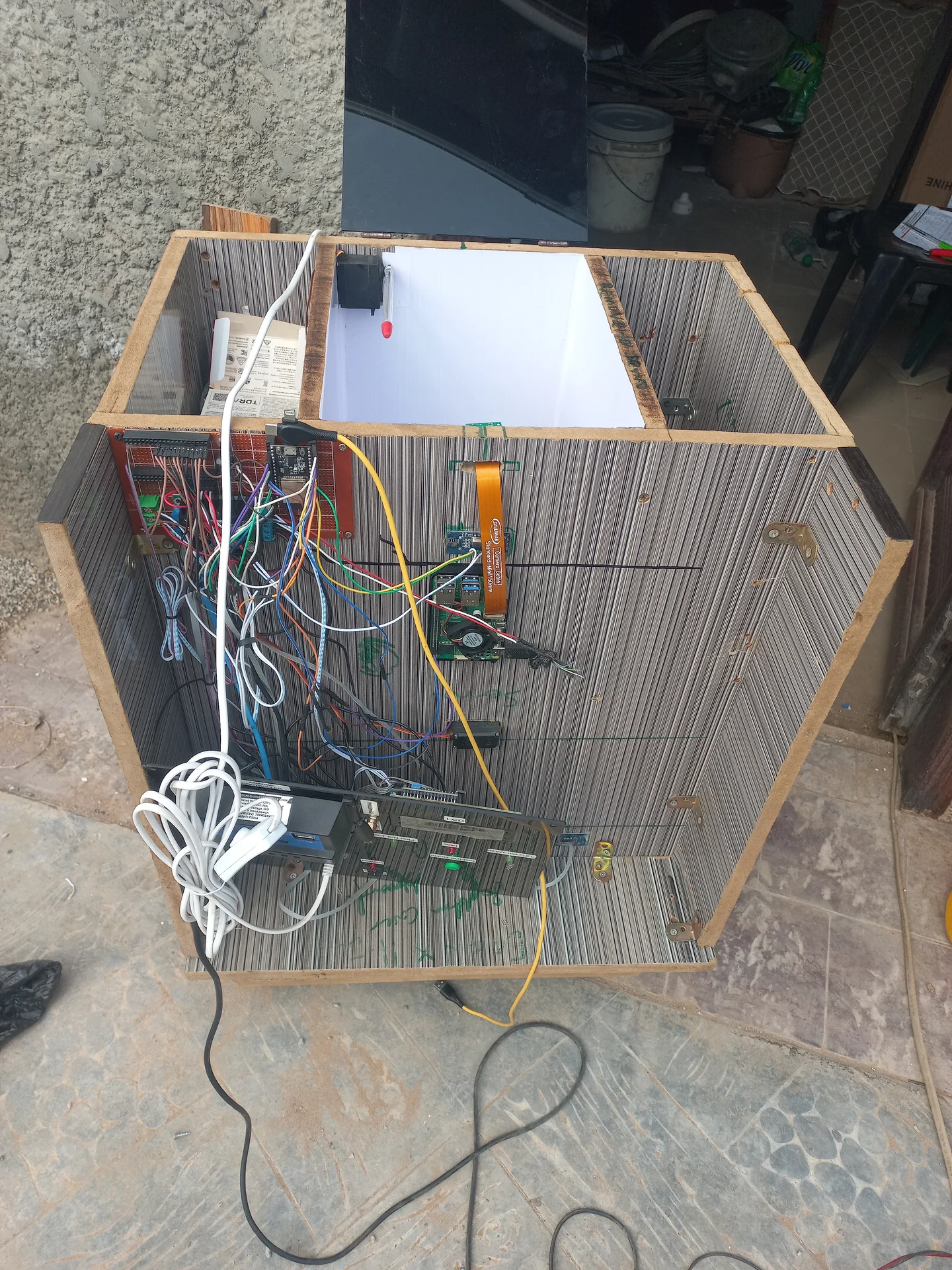
Full Proteus circuit diagram showing the complete wiring of the ESP32, Raspberry Pi 5, HC-SR04 ultrasonic sensors, servo motor, SIM800L GSM module, 20×4 LCD, LEDs, buzzer, XL4016 300W DC-DC buck converter, solar charge controller, and VINTAGE battery.
The deposit compartment uses a dedicated state machine to prevent false triggers and
ensure the item has fully settled before a camera scan is requested. The machine has
three states. The sort result from the Pi is handled separately in
handleSerial() when UART data arrives, keeping the deposit states clean
and non-blocking.
States: DEP_IDLE → DEP_TRIGGERED →
DEP_COOLDOWN → DEP_IDLE
millis() timestamp and transitions
to DEP_TRIGGERED.SCAN\n to the Raspberry Pi over
Serial2 (UART). The deposit machine then remains in DEP_TRIGGERED; it does not
advance further on its own. Advancement happens inside handleSerial()
when the Pi replies with R\n or N\n.handleSerial() after
processWaste() completes. A 10-second millis()
timer runs. Any object detected during this window is ignored. When the timer
expires, transitions back to DEP_IDLE.
The UART handler handleSerial() runs every main-loop iteration. When
the deposit machine is in DEP_TRIGGERED and the Pi sends R\n or
N\n, handleSerial() calls
processWaste(isRecyclable), records the cooldown timestamp, and
advances the deposit state to DEP_COOLDOWN.
All messages are newline-terminated ASCII strings at 115200 baud.
| Direction | Message | Meaning |
|---|---|---|
| ESP32 → Pi | SCAN\n |
Item settled in deposit; request classification |
| Pi → ESP32 | R\n |
Classify as Recyclable, sort left |
| Pi → ESP32 | N\n |
Classify as Non-Recyclable, sort right |
| Pi → ESP32 | READY\n |
Pi boot complete; system handshake |
| Pi → ESP32 | WIFI_OK\n |
Pi has internet connectivity |
| Pi → ESP32 | WIFI_NO\n |
Pi has no internet (non-critical; NCNN runs offline) |
The full sketch is available on GitHub. Below are the three most architecturally significant routines from the Arduino sketch.
moveAndDetach() and Cover ManagementThe sort servo uses moveAndDetach(): it attaches, sweeps
from startPos to endPos one degree at a time, then detaches
the PWM signal. Detaching eliminates the constant buzz and heat generated when a servo
is commanded to hold a position against mechanical resistance with an active PWM signal.
The cover servo is permanently attached and uses incremental writes
(slower for opening, faster for closing) to move smoothly; it holds its position via
the kept-alive PWM signal.
// Sort servo: sweep from startPos to endPos, then detach PWM.
void moveAndDetach(Servo &s, int pin, int startPos, int endPos, int stepDelay) {
    s.attach(pin);
    if (startPos < endPos) {
        for (int pos = startPos; pos <= endPos; pos++) { s.write(pos); delay(stepDelay); }
    } else {
        for (int pos = startPos; pos >= endPos; pos--) { s.write(pos); delay(stepDelay); }
    }
    delay(200);
    s.detach();   // cut PWM signal — servo is now silent and cool at rest
}

// Cover servo: stays attached; incremental writes for smooth travel.
void openTopCover() {
    if (!isCoverOpen) {
        for (int pos = 90; pos >= 0; pos--) { coverServo.write(pos); delay(15); }
        isCoverOpen = true;
    }
}
void closeTopCover() {
    if (isCoverOpen) {
        for (int pos = 0; pos <= 90; pos++) { coverServo.write(pos); delay(5); }
        isCoverOpen = false;
    }
}

void processWaste(bool isRecyclable) {
    if (leftBinLocked || rightBinLocked) {
        currentActionMsg = "FULL! DO NOT DUMP!";
        return;
    }
    if (isRecyclable) {
        currentActionMsg = "Sorting Recyclable!";
        moveAndDetach(sortServo, sortServoPin, 90, 0, 0);    // pivot left (0°)
        delay(1500);
        moveAndDetach(sortServo, sortServoPin, 0, 90, 0);    // return to centre
    } else {
        currentActionMsg = "Sorting Non-Recyc..";
        moveAndDetach(sortServo, sortServoPin, 90, 180, 0);  // pivot right (180°)
        delay(1500);
        moveAndDetach(sortServo, sortServoPin, 180, 90, 0);  // return to centre
    }
}readDepositSensor()Runs every loop iteration. Uses millis()-based timers so the main loop
never blocks during the 5-second settle or 10-second cooldown windows.
Result handling is in handleSerial(), keeping the deposit states clean.
const float DEPOSIT_THRESHOLD   = 25.0;   // cm — object closer than this triggers a scan
const long  DEPOSIT_SETTLE_MS   = 5000;   // ms — settle window before SCAN is sent
const long  DEPOSIT_COOLDOWN_MS = 10000;  // ms — lockout after sort completes

void readDepositSensor() {
    float dist = getDistance(TRIG3, ECHO3);   // US3: TRIG=GPIO 26, ECHO=GPIO 32

    switch (depositState) {
        case DEP_IDLE:
            if (dist > 0 && dist < DEPOSIT_THRESHOLD) {
                depositTriggerTime = millis();
                depositState = DEP_TRIGGERED;
            }
            break;

        case DEP_TRIGGERED:
            if (millis() - depositTriggerTime >= DEPOSIT_SETTLE_MS) {
                Serial2.println("SCAN");    // request Pi classification
                // remain here until handleSerial() receives R or N
            }
            break;

        case DEP_COOLDOWN:
            if (millis() - depositCooldownStart >= DEPOSIT_COOLDOWN_MS) {
                depositState = DEP_IDLE;    // ready for next deposit
            }
            break;
    }
}

// Called every loop iteration; advances deposit machine on Pi reply
void handleSerial() {
    if (Serial2.available()) {
        String incoming = Serial2.readStringUntil('\n');
        incoming.trim();

        if (depositState == DEP_TRIGGERED) {
            if (incoming == "R" || incoming == "N") {
                processWaste(incoming == "R");
                depositCooldownStart = millis();
                depositState = DEP_COOLDOWN;
            }
        }
        if (incoming == "READY") {
            // Pi boot handshake; open cover if bins are not full
            if (!leftBinLocked && !rightBinLocked) { openTopCover(); }
            updateLCD();
        } else if (incoming == "WIFI_OK") {
            wifiStatus = "WiFi: OK";  updateLCD();
        } else if (incoming == "WIFI_NO") {
            wifiStatus = "WiFi: --";  updateLCD();
        }
    }
}checkBinLevels()Bin readings are confirmed over a 4.5-second window to prevent the sorting platform itself from triggering a false "full" reading as waste passes in front of the sensor during sorting.
#define FULL_THRESHOLD   10   // cm — bin is full below this distance
#define CONFIRM_DELAY  4500   // ms — reading must persist to count as full

void checkBinLevels() {
    float distL = getDistance(TRIG1, ECHO1);   // Left  (Recyclable)
    float distR = getDistance(TRIG2, ECHO2);   // Right (Non-Recyclable)
    unsigned long now = millis();

    // ── Left bin ────────────────────────────────────────────────────────
    if (distL > 0 && distL < FULL_THRESHOLD && !leftBinFull) {
        if (!leftConfirmStart) leftConfirmStart = now;
        else if (now - leftConfirmStart >= CONFIRM_DELAY) {
            leftBinFull = true;
            sendGSMAlert("LEFT");           // SMS to operator
            digitalWrite(LED_L, HIGH);
        }
    } else {
        leftConfirmStart = 0;               // reset timer on clear reading
    }
    // ── Right bin (same logic) ──────────────────────────────────────────
    // ...
}moveAndDetach(): attach → sweep
one degree at a time to target → detach PWM. Detaching eliminates the constant
buzz and heat that occur when a servo holds a position against mechanical resistance
with an active PWM signal indefinitely.setup()
onward. It uses slower incremental writes for opening (15 ms per degree) and faster
writes for closing (5 ms per degree). The continuous PWM signal is intentional: the
cover must hold firm against gravity, so keeping the signal active is correct.
Both servos default to 90° (closed / centred) at startup before
setup() opens the cover if the bins are not already full.
Ten real hardware and software engineering challenges were solved during development. Each solution directly shaped the final system architecture.
A piece of waste falling through the air momentarily reflects sound waves, making the bin appear full before it lands. The fix was an Obstruction Verification Delay: the ESP32 sets a flag and starts a millis() timer. Only if the reading stays below FULL_THRESHOLD continuously for 4.5 seconds is the bin officially locked. Transient reflections clear themselves.
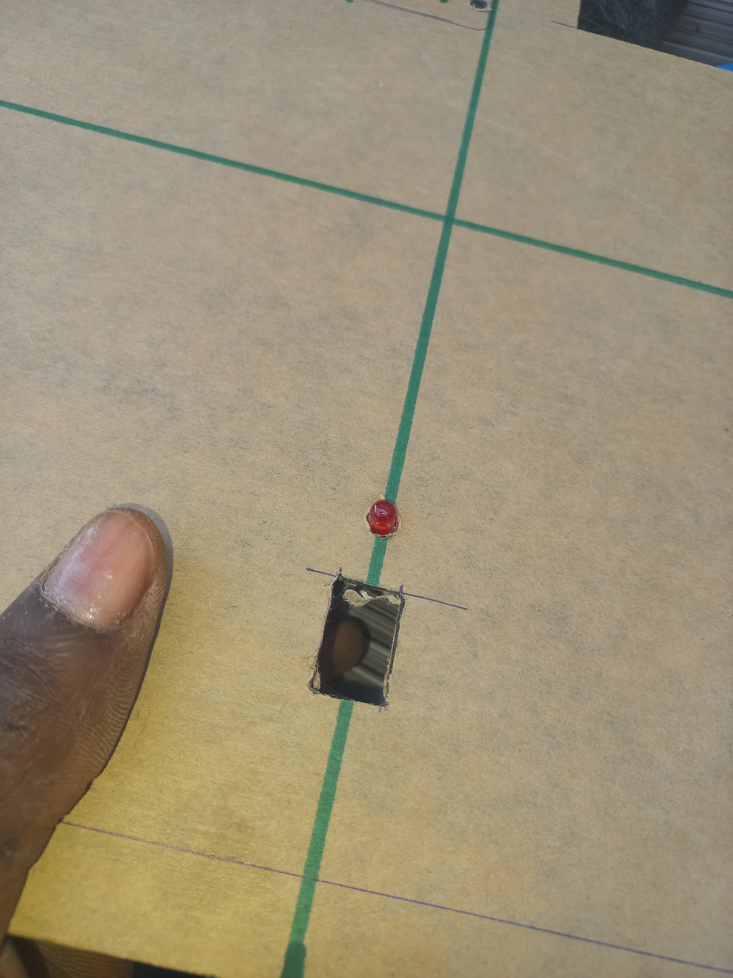
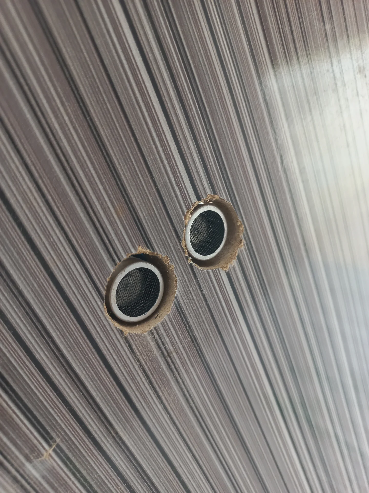
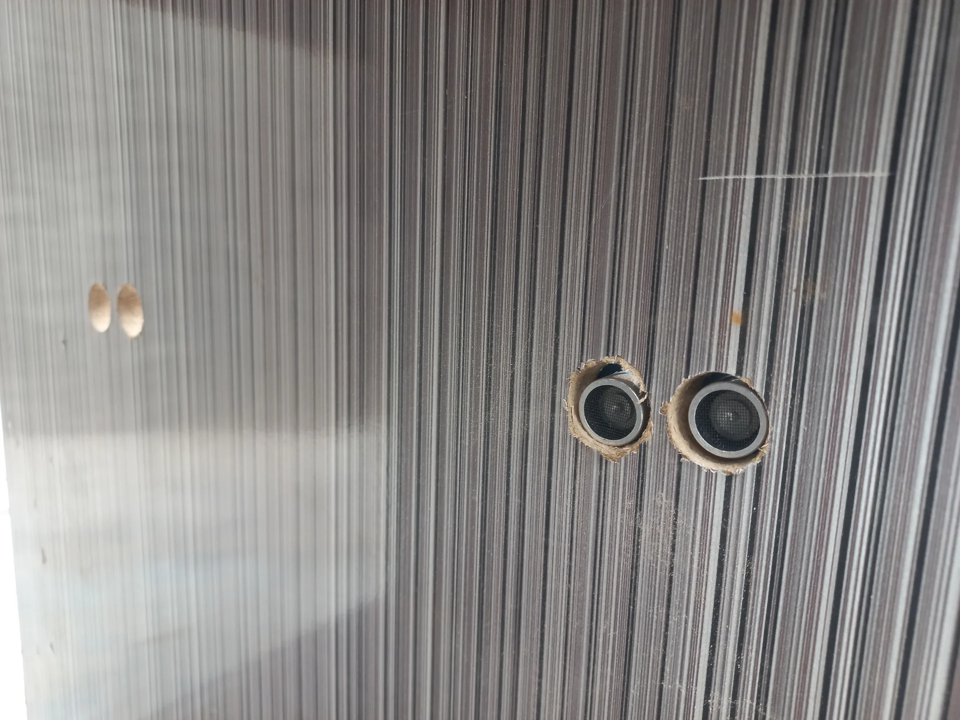
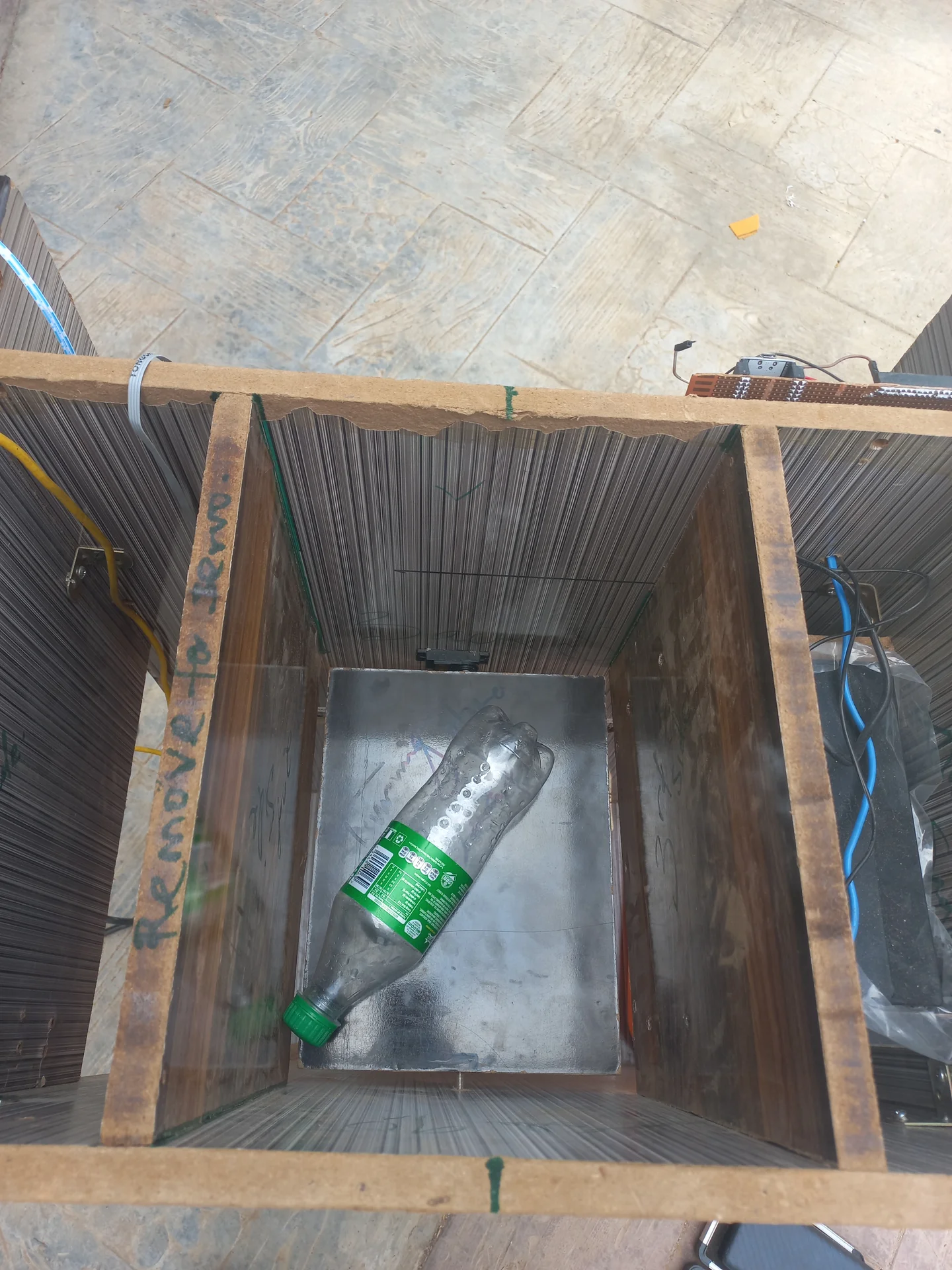
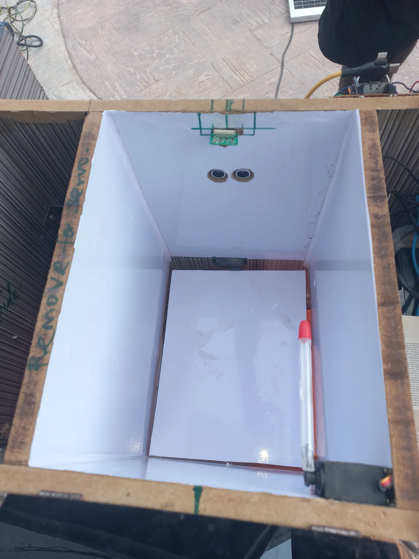
Downward-pointing sensors produce inaccurate fill levels because waste piles unevenly (a bottle standing upright in the centre triggers a false "full" while 90% of the space is empty). Mounting sensors horizontally across the brim turns them into a tripwire: any reading below 16 cm means the horizontal beam is physically blocked, which only happens when the bin is actually full.
At 30 fps, the Pi would send 30 classification signals per second, flooding the ESP32 serial buffer and causing the servo to repeat its sweep until the system crashed. The solution was a Handshake & Cooldown Protocol: after sending one R\n or N\n, the Pi enters a 5-second STATE_RESTING. On the ESP32 side, immediately after executing the mechanical sweep, a buffer flush loop reads and discards any stale serial bytes before accepting the next command.
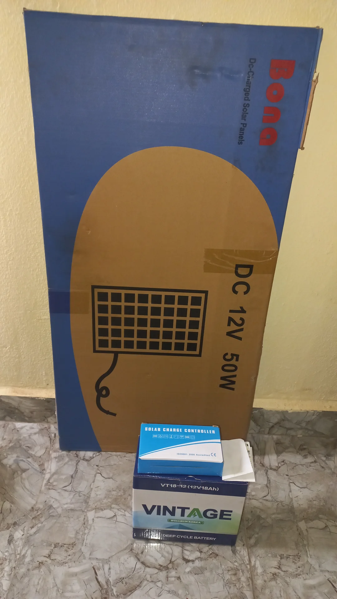
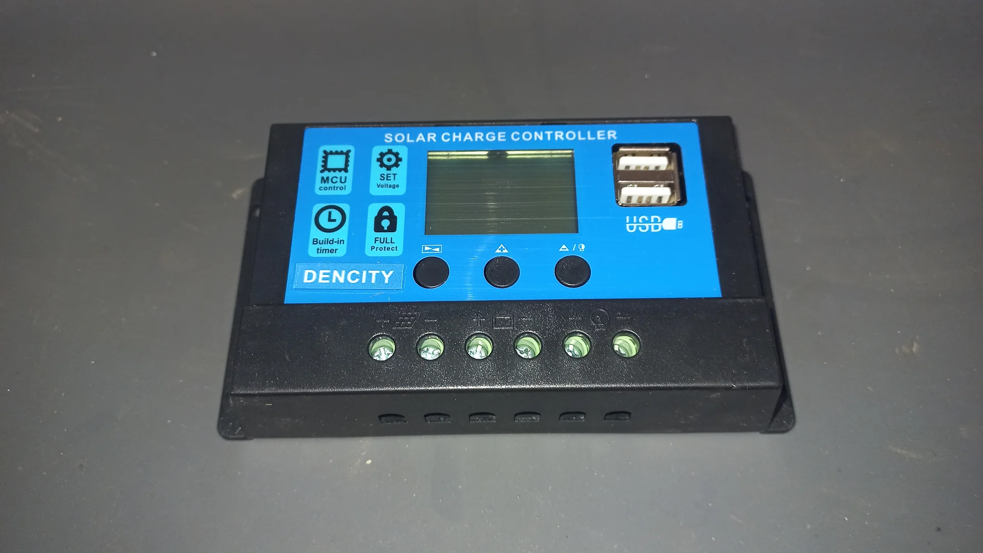
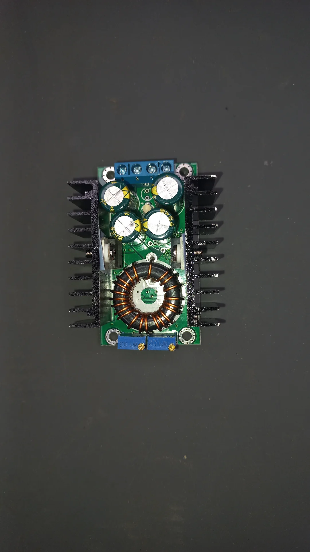
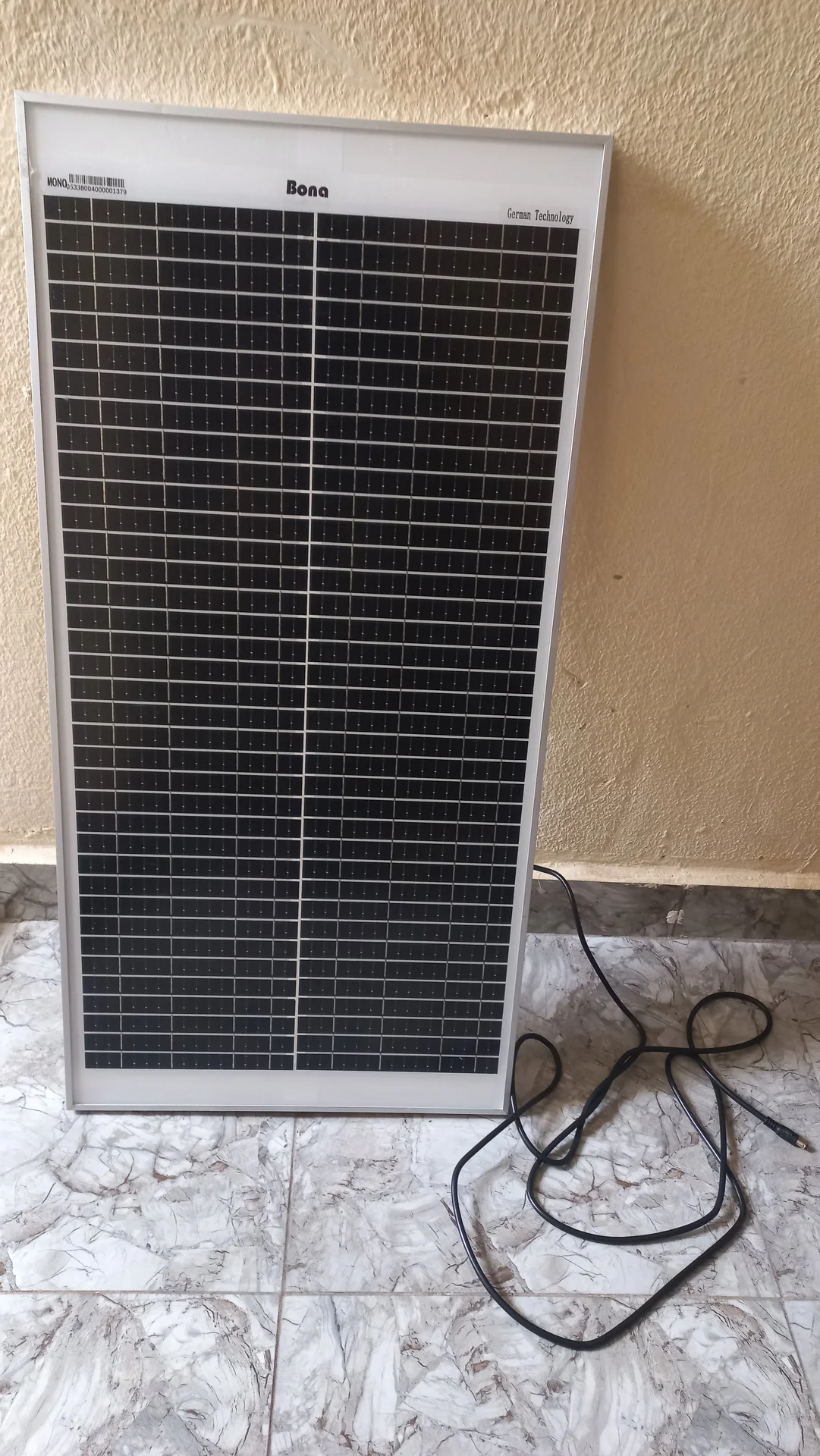
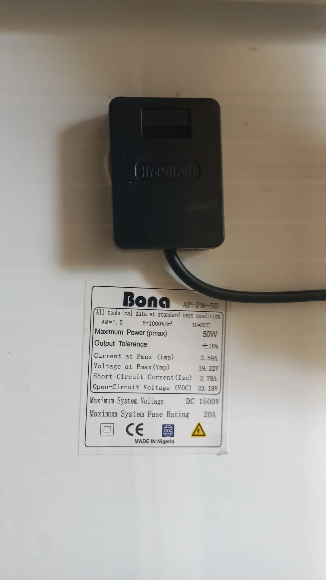
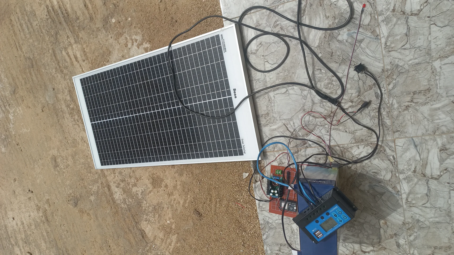
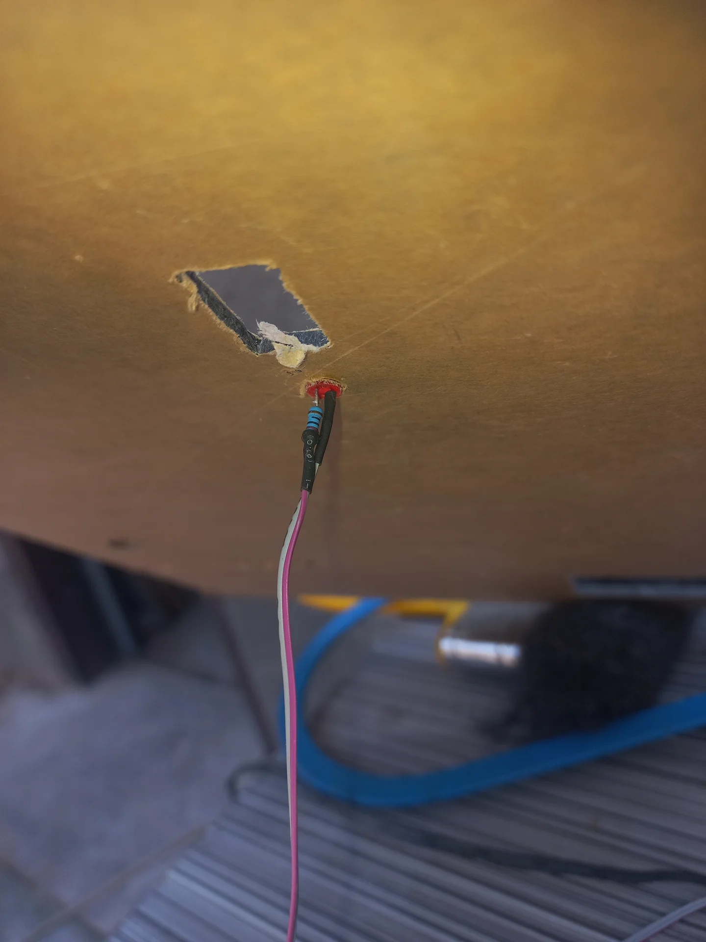
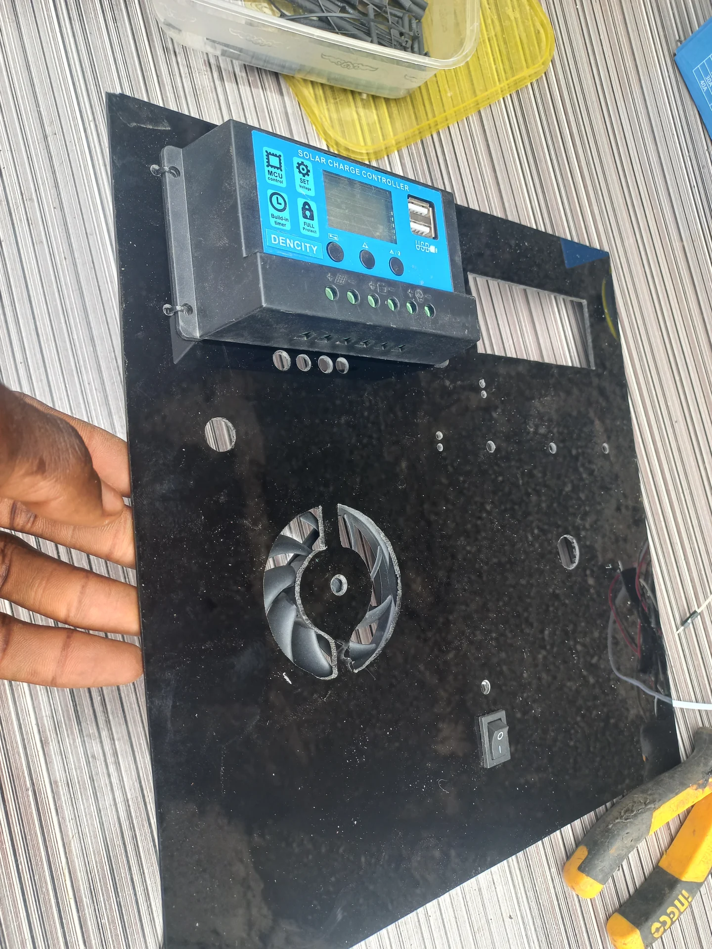
The Pi 5 displayed a lightning-bolt low-voltage warning; vcgencmd get_throttled returned 0xd0000, confirming active CPU throttling. The fix involved three steps: replacing thin jumper wires with high-gauge copper wire to lower resistance; tuning the XL4016 300W DC-DC buck converter to output 5.39–5.40 V (a deliberate over-voltage to compensate for remaining wire drop under load); and turning the current potentiometer to maximum to keep the module in Constant Voltage (green LED) mode. Stress-tested with stress -c 4 -t 60 achieving throttled=0x0.
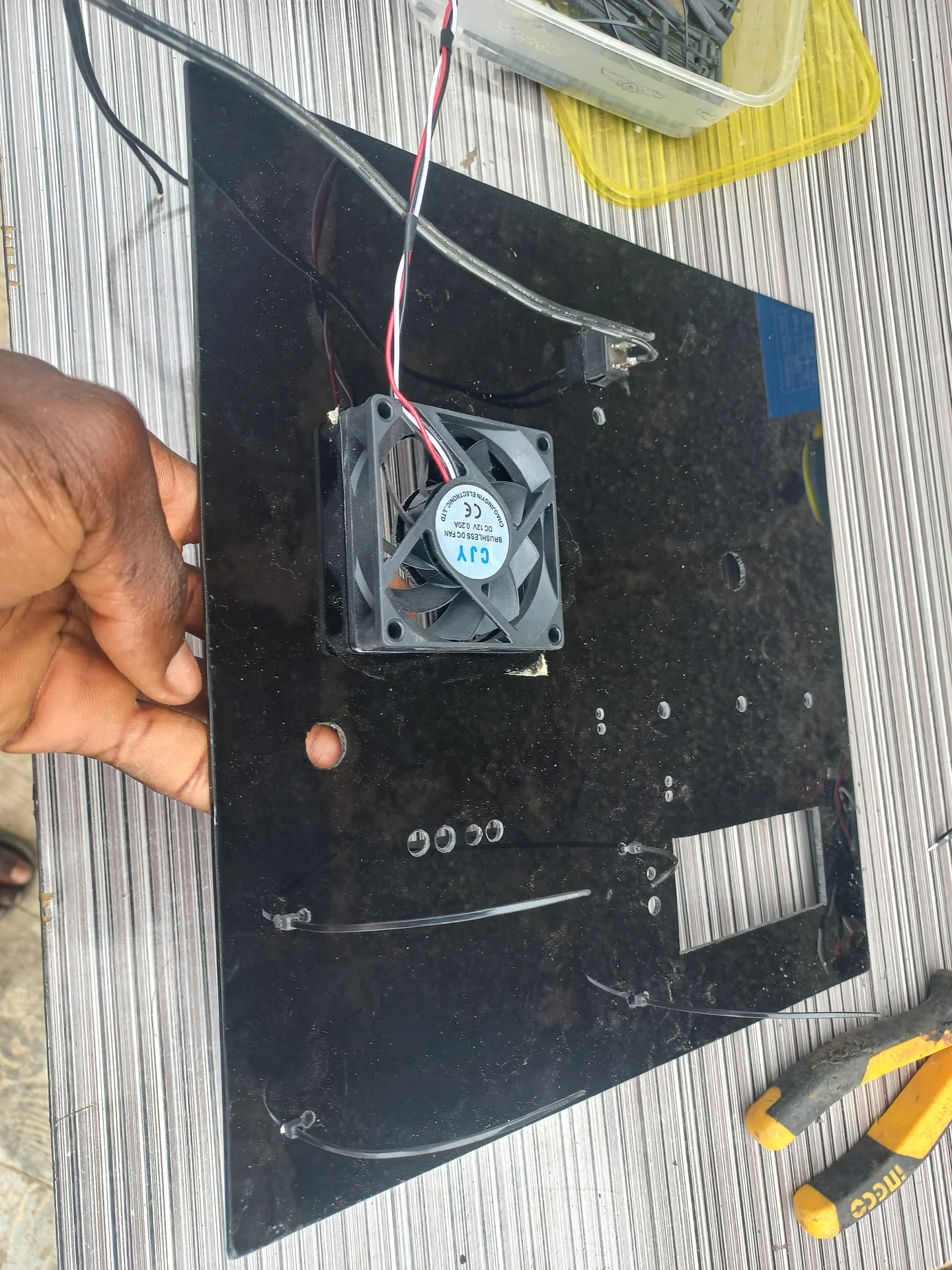
The sorting servo buzzed and shook continuously when holding the centre position because the ESP32's PWM signal made the servo motor micro-correct against gravity indefinitely. A "Quiet Mode" (Detach Logic) was implemented: moveAndDetach() attaches the servo, sweeps it to the target angle, waits 200 ms for physical arrival, then calls sortServo.detach() to cut the PWM signal entirely. The top-cover servo intentionally retains continuous attachment to maintain holding torque.
Due to how the servo horn was physically mounted, the expected open/close directions were reversed and the original per-trash-item actuation was slow and awkward. The redesign redefined 0° = OPEN, 90° = CLOSED and repurposed the cover as a System Lockout Hatch: permanently open during normal operation, closing only when a bin is full. Smooth actuation functions (openTopCover() / closeTopCover()) use 15 ms per-degree delays to prevent violent jerks.
Running YOLO continuously at 30 fps while the bin was idle caused the Pi to run hot and risk "phantom" detections (e.g., a blue shirt triggering "Plastic"). A third ultrasonic sensor in the deposit compartment solved this: when a user's hand is detected (<25 cm), the ESP32 waits 4 seconds for the hand to leave and the item to stop wobbling, then sends a single SCAN\n UART command. The Pi's 5-state machine keeps YOLO completely bypassed in WAITING and RESTING states, running inference only during SCANNING and STABILIZING.
Serial2.readStringUntil('\n') is a blocking call: a malformed message without a newline would freeze the entire ESP32 loop() for 1,000 ms, causing sensor misses and an unresponsive button. The fix was a single line in setup(): Serial2.setTimeout(50);. This caps the blocking wait at 50 ms, keeping the main loop effectively real-time.
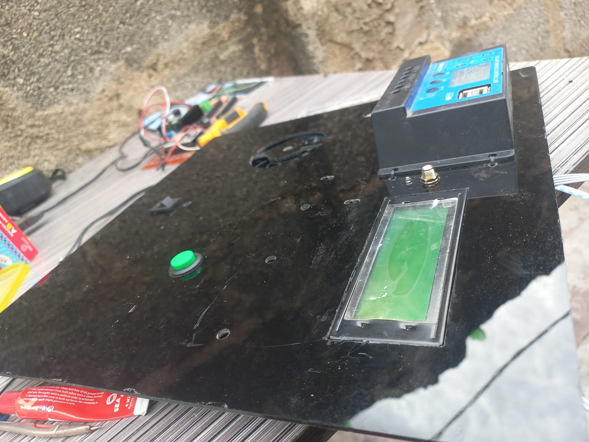
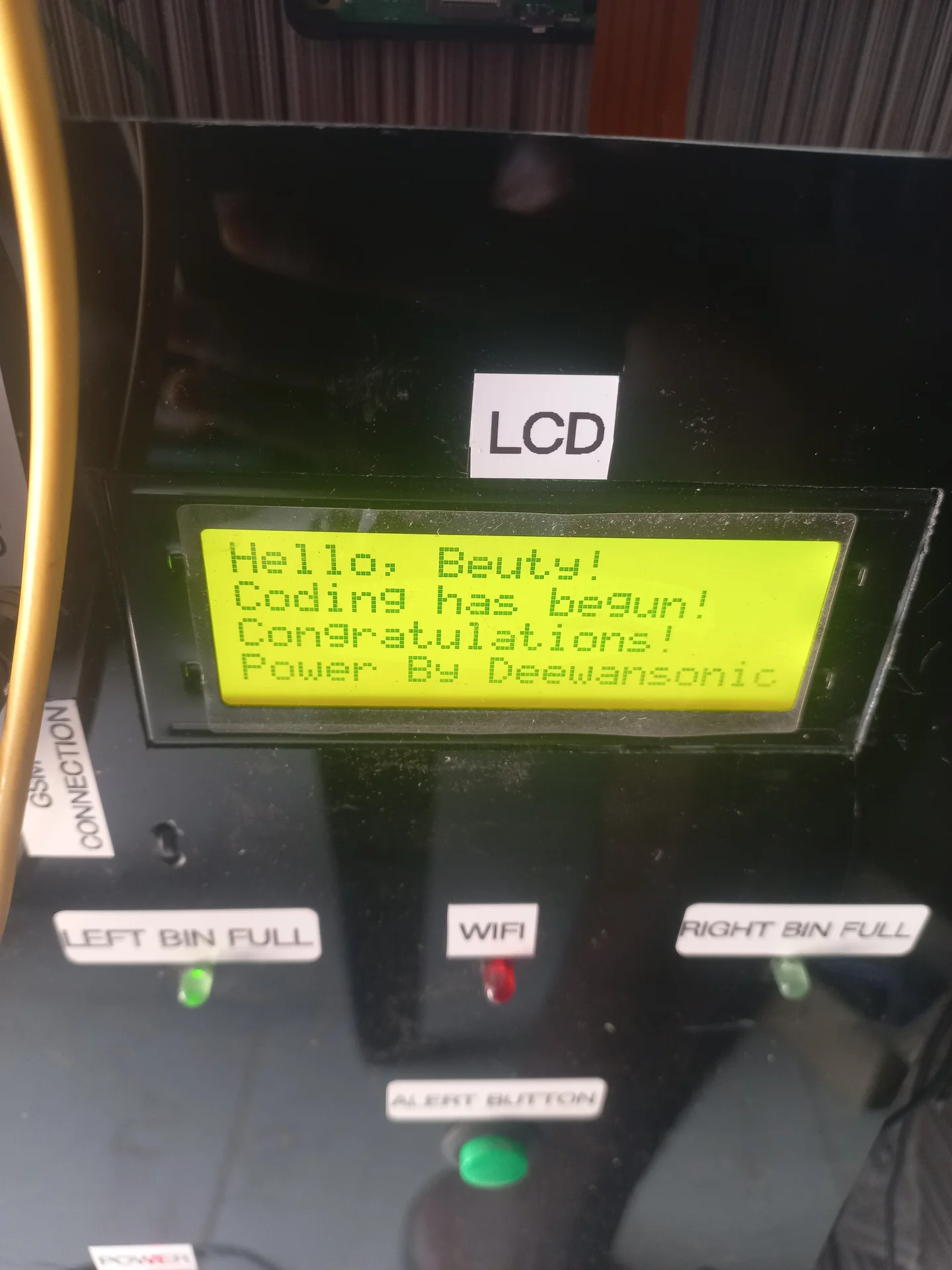
The ESP32 boots in ~1 second; the Pi takes ~30 seconds to load the OS, Python, the NCNN model, and the camera. Without synchronisation, the ESP32 had no way to know when the AI was actually ready. The Pi script sends READY\n the moment initialisation completes, followed by WIFI_OK\n or WIFI_NO\n after pinging Google DNS. The ESP32 catches these signals and advances the LCD through a multi-stage splash screen, finally settling on "Waiting for waste..".
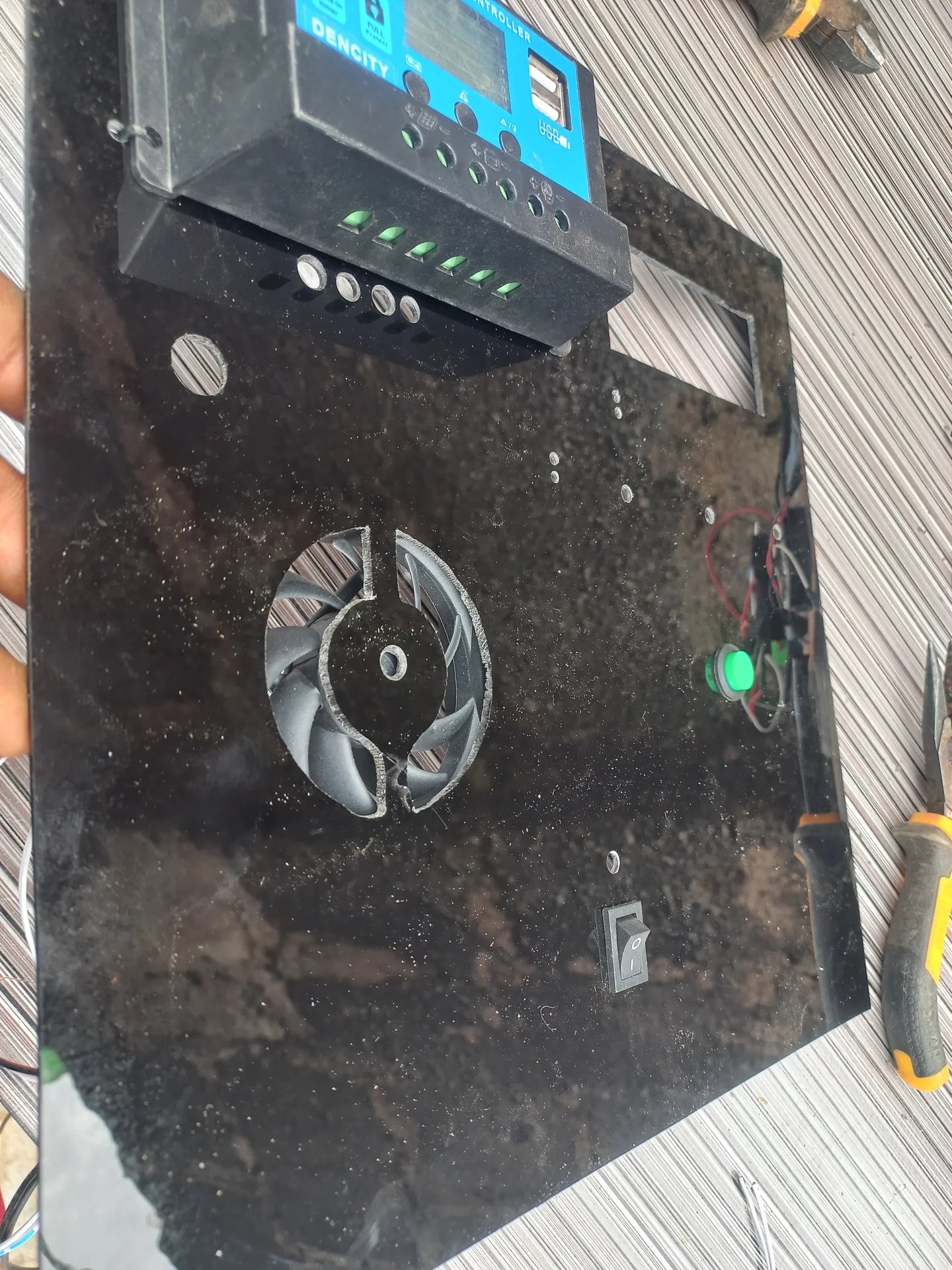
Even after a janitor empties a full bin, the sensor instantly reads clear. If the code unlocked automatically, any debris falling over could trigger infinite lock/unlock loops. The design requires manual acknowledgment: leftBinLocked stays true until the janitor presses the physical push button (Pin 13). A 50 ms debounce filter ensures clean presses. On press, all lock booleans and SMS flags are reset, the buzzer beeps once to confirm, and the top cover sweeps open.
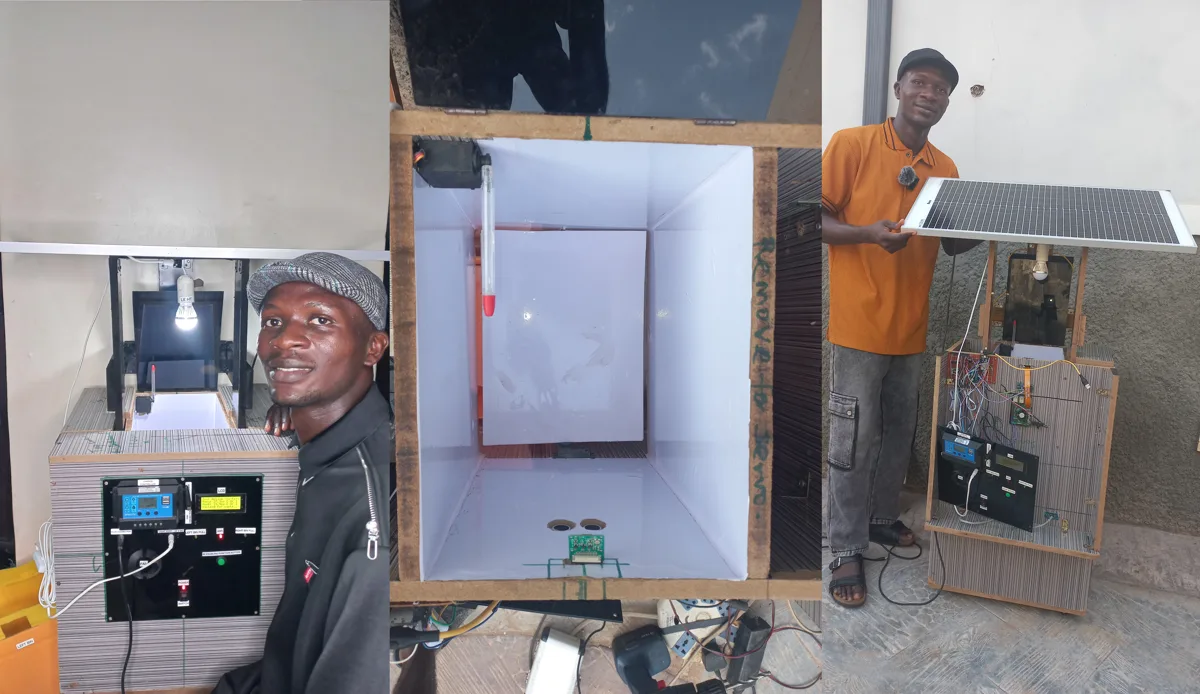
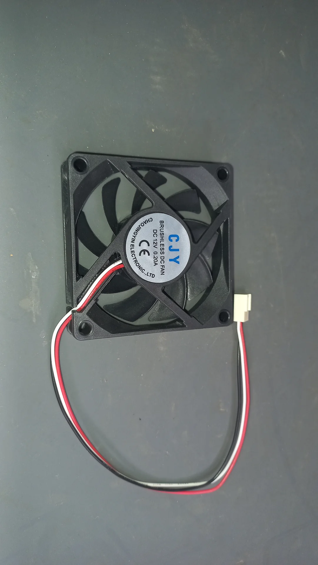
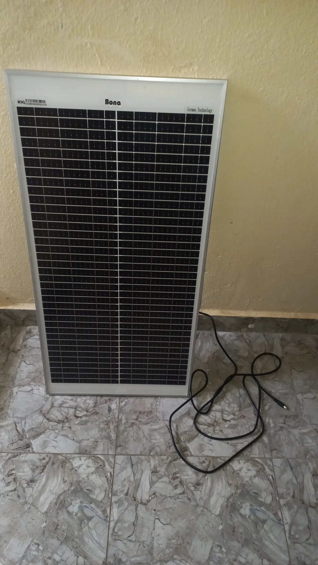
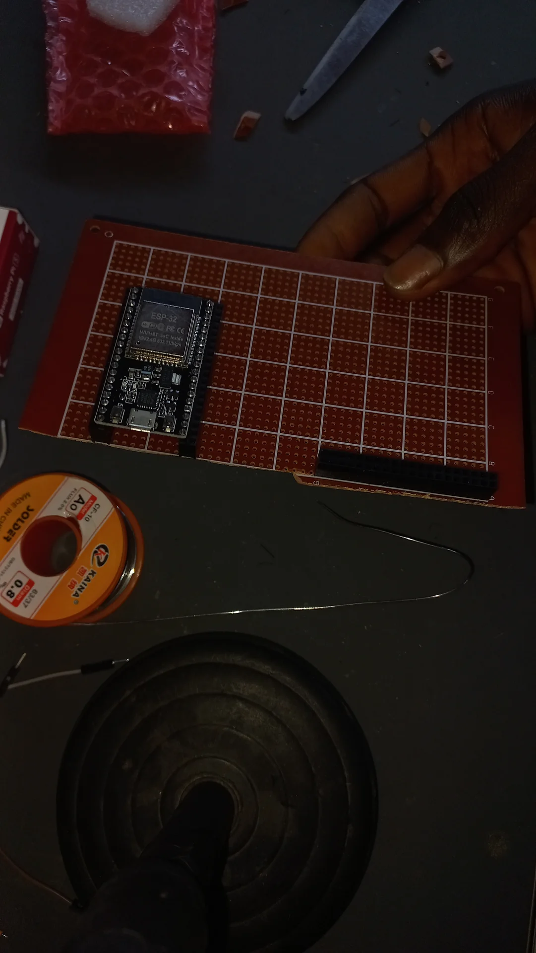
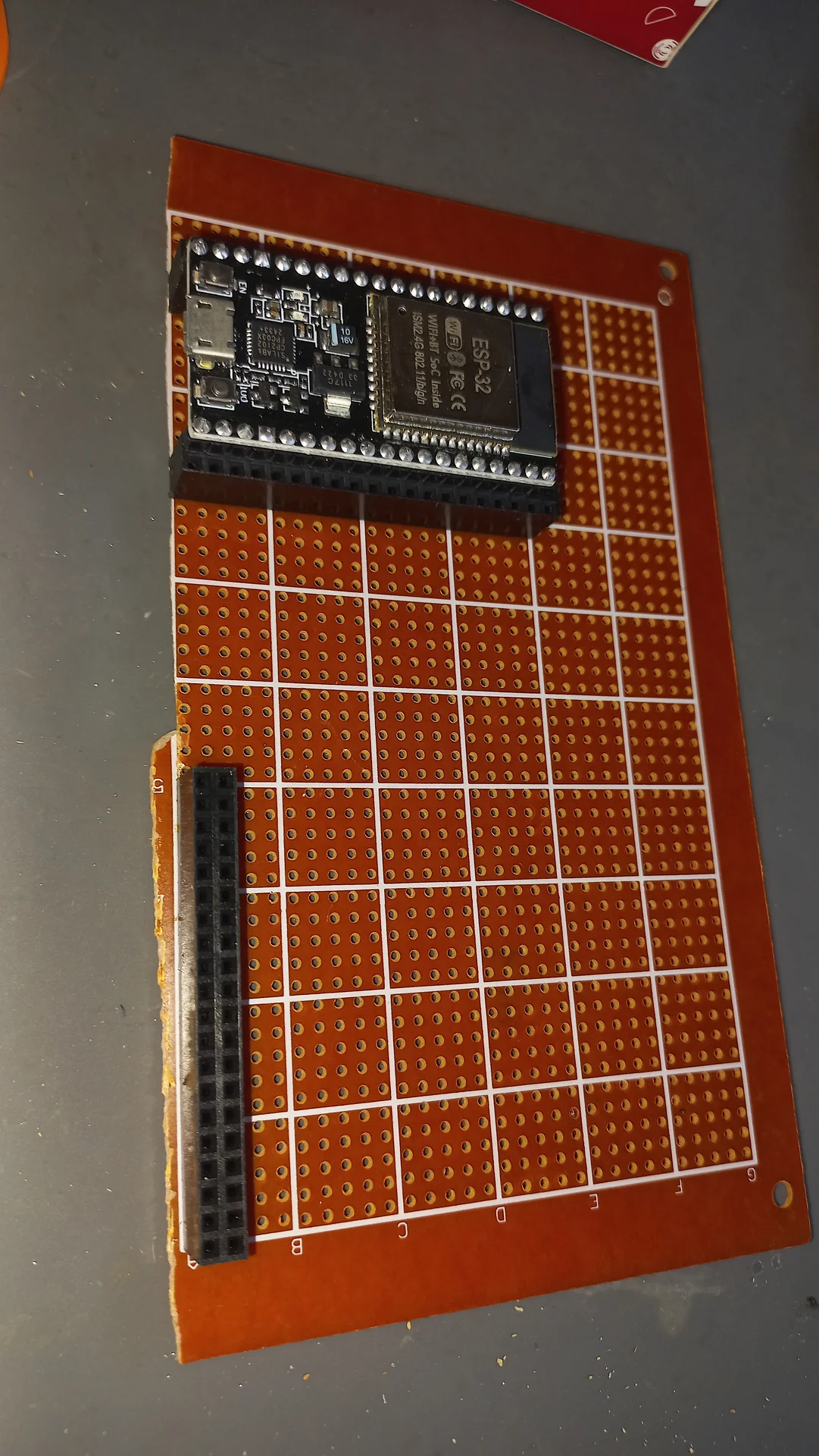
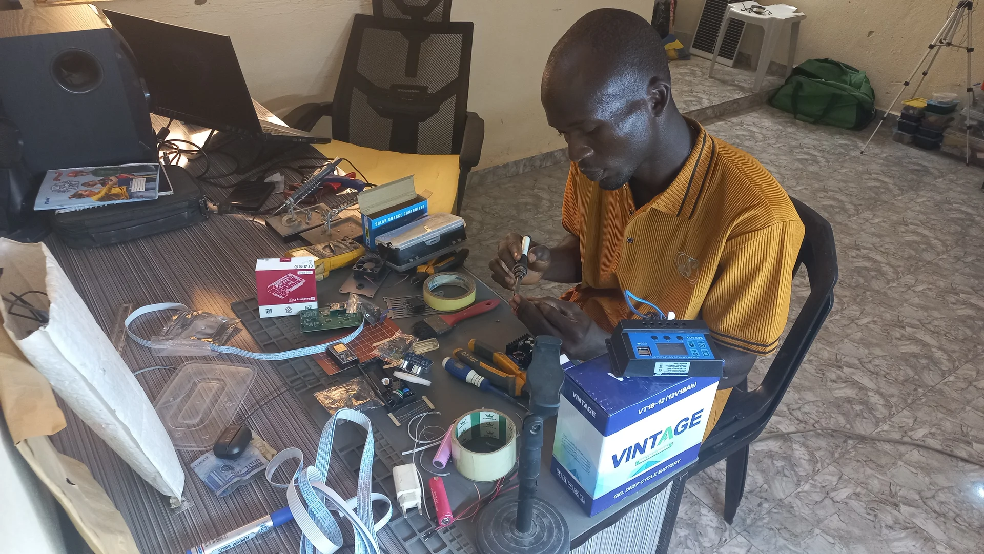
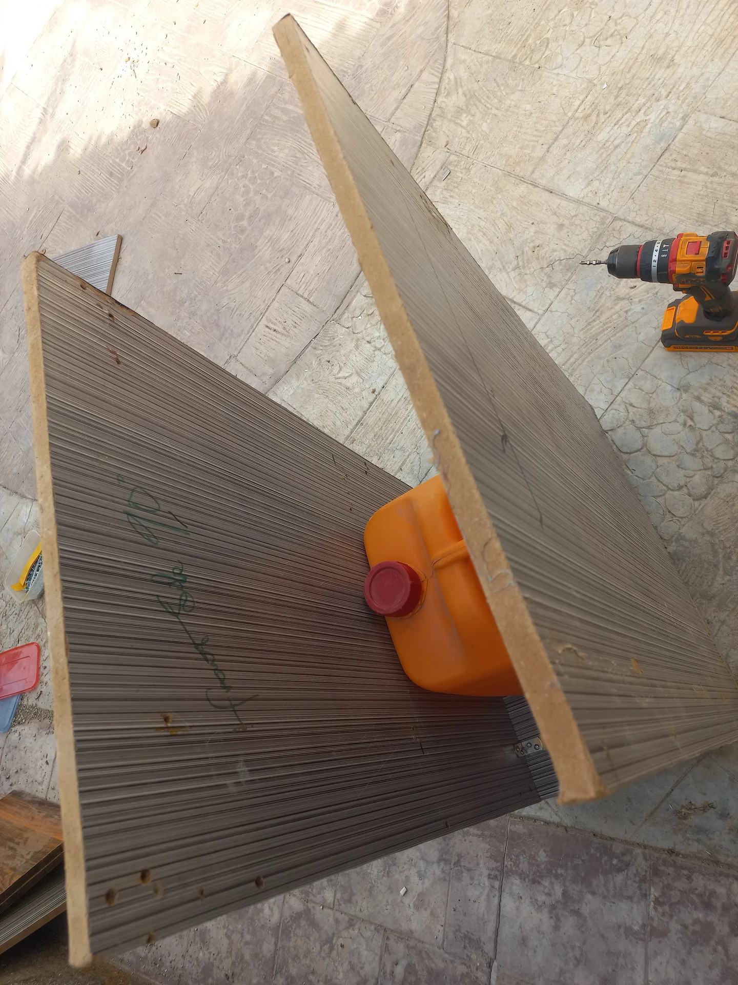
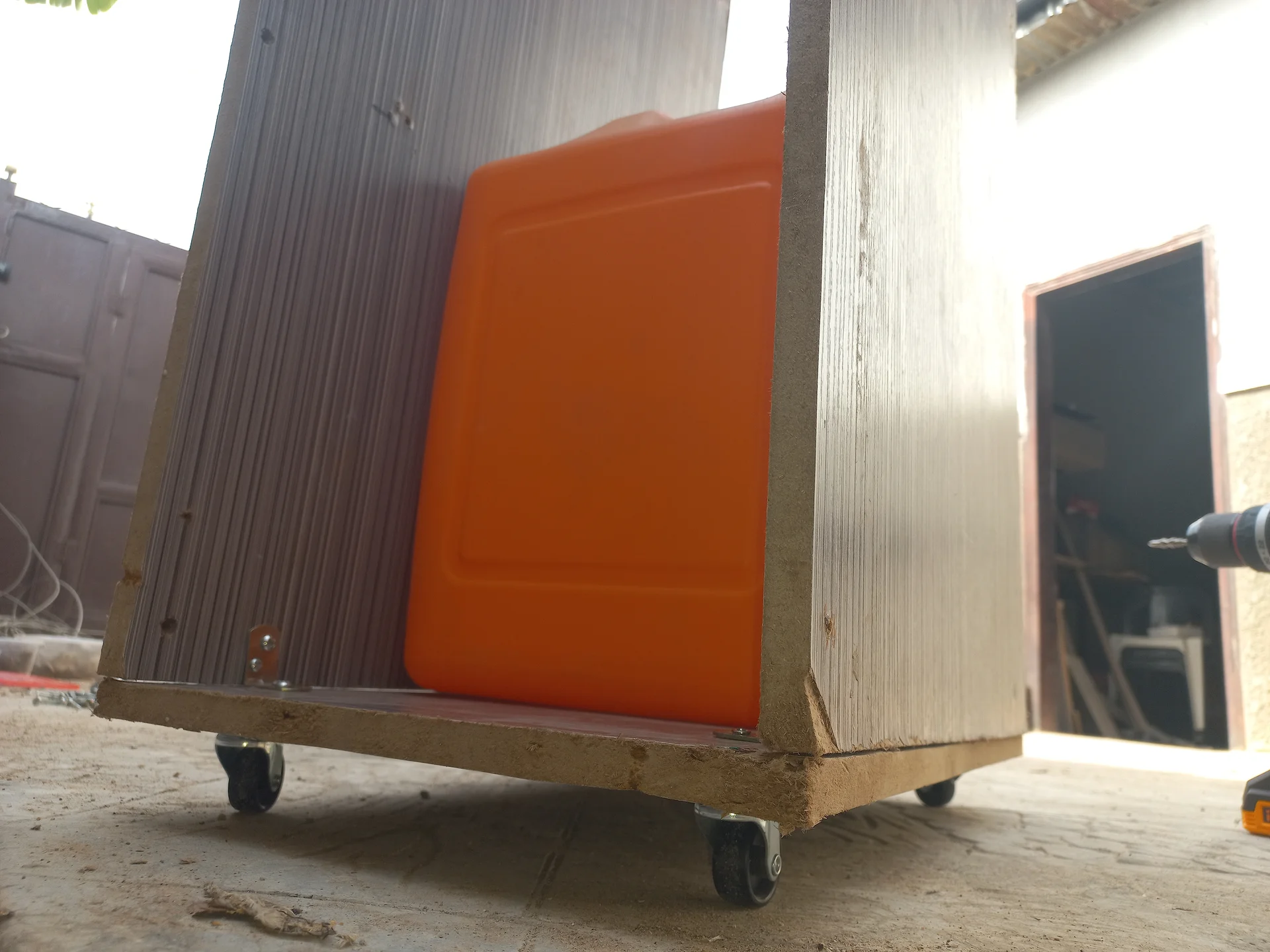
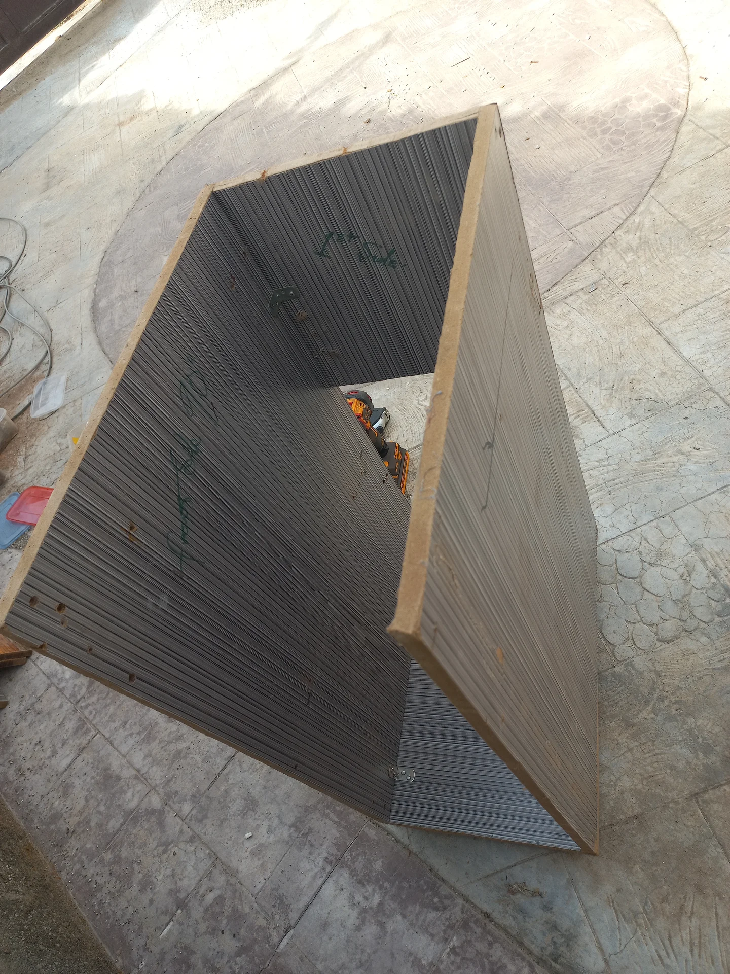
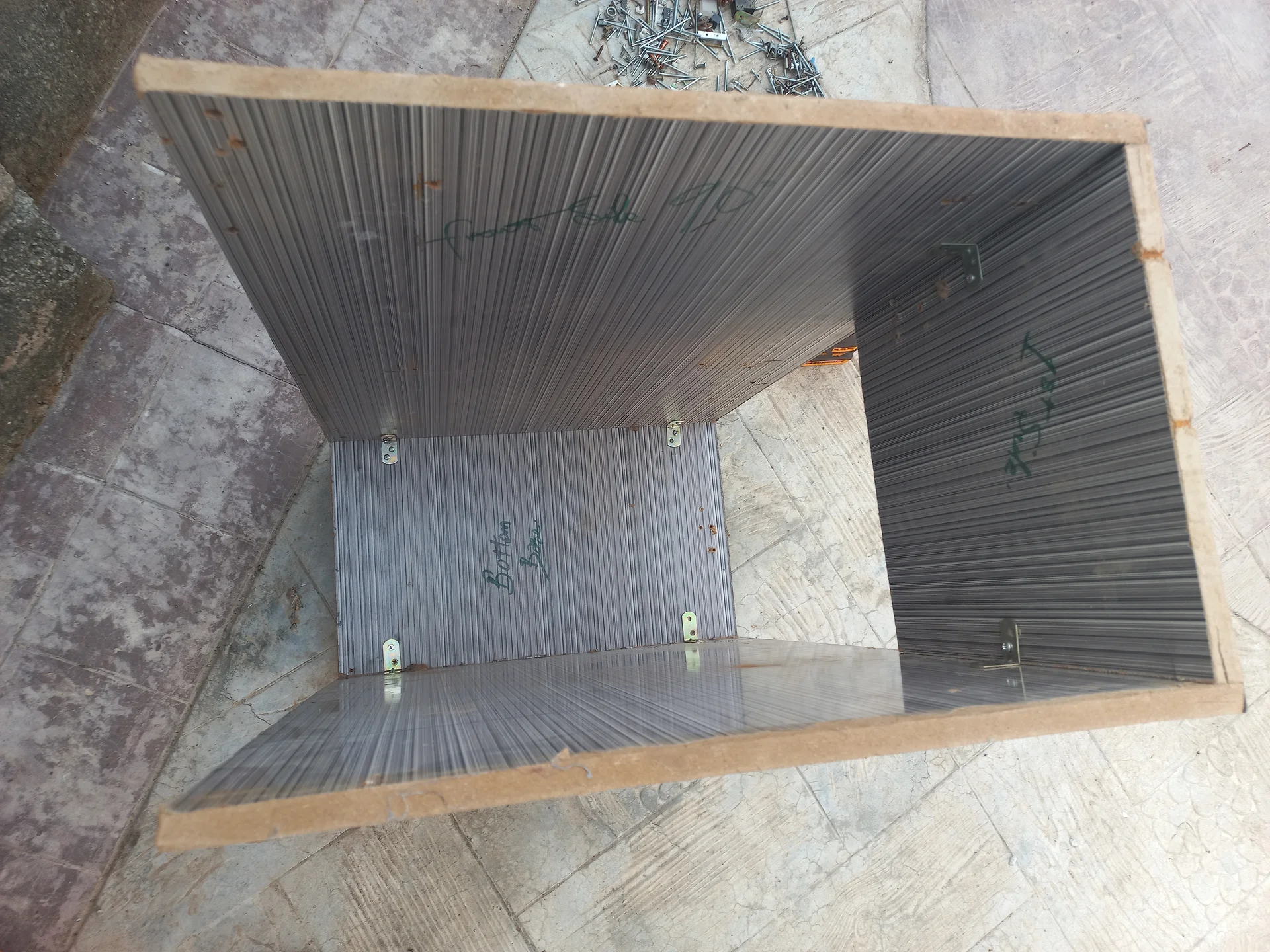
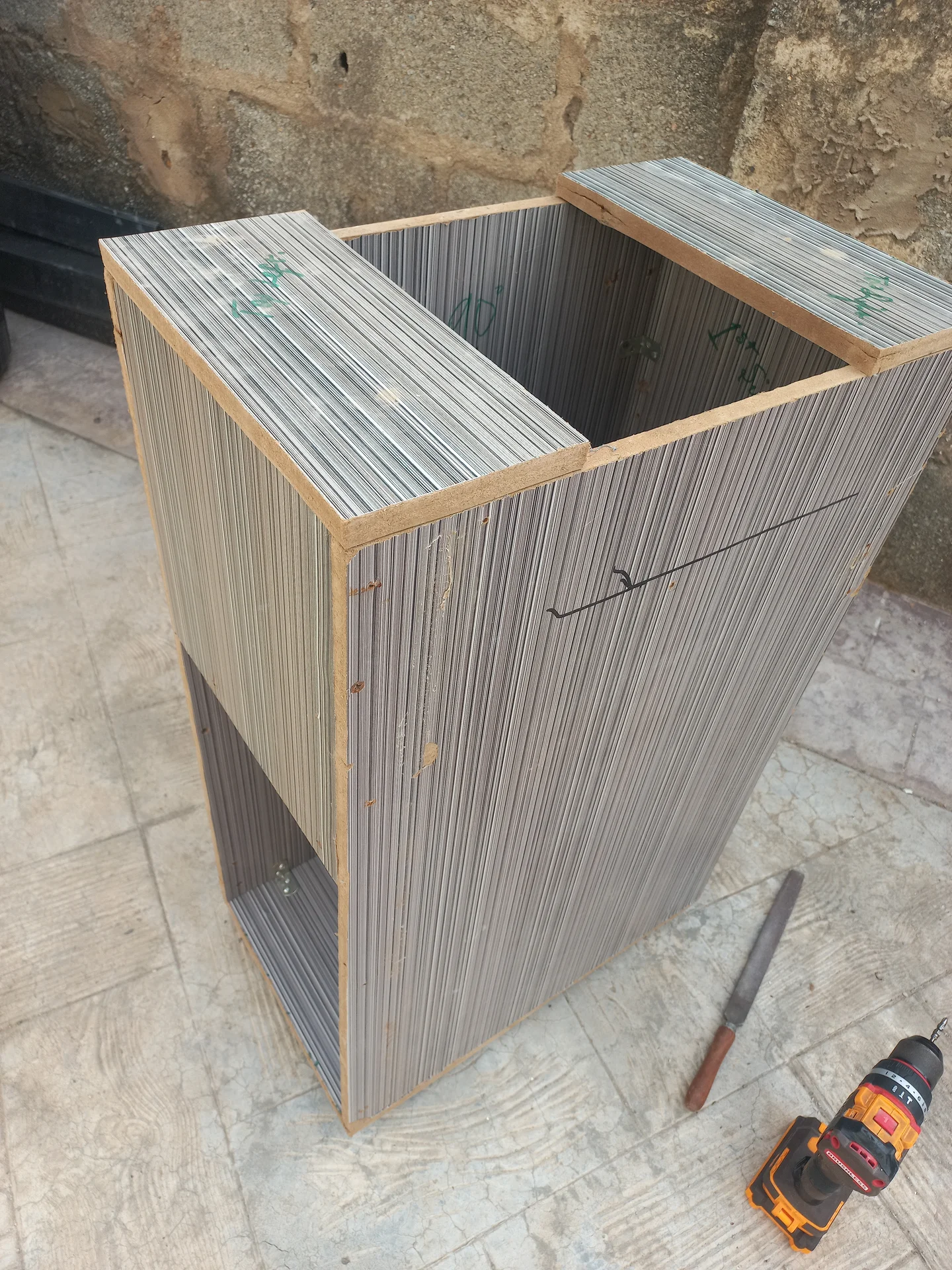
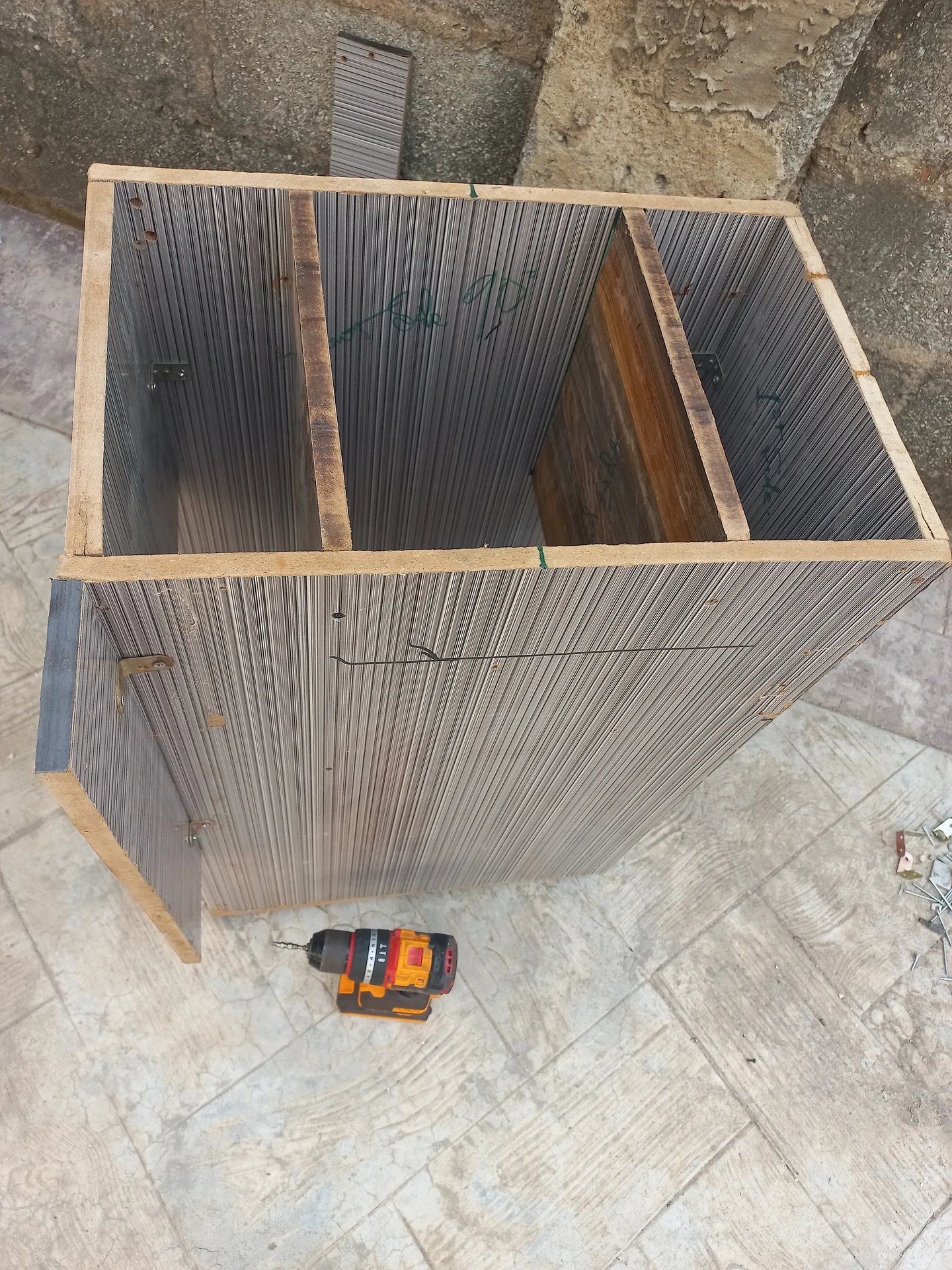
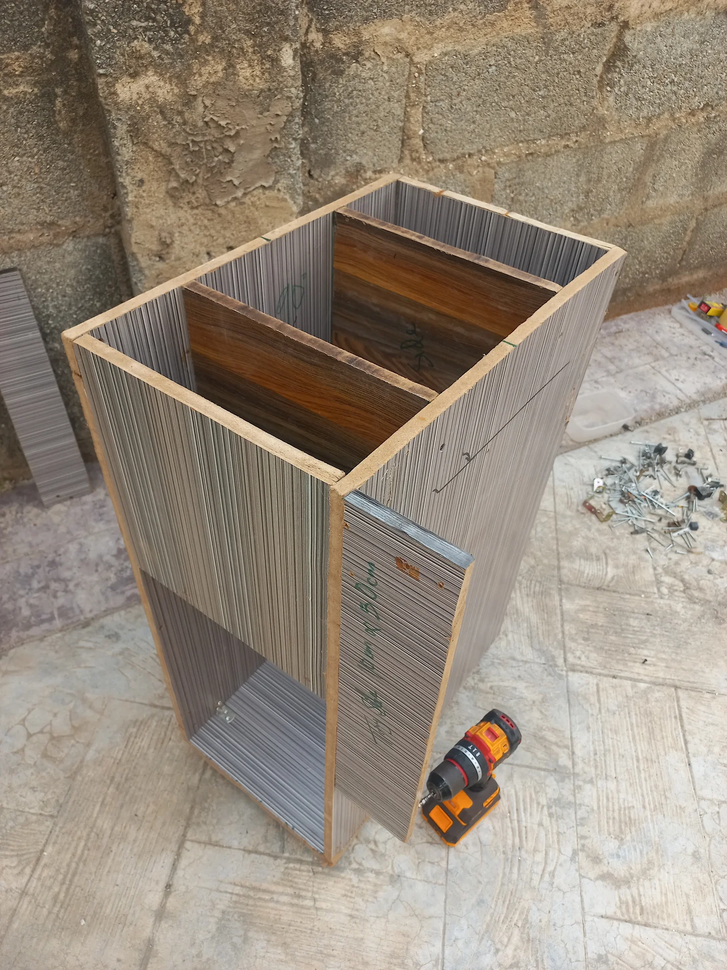
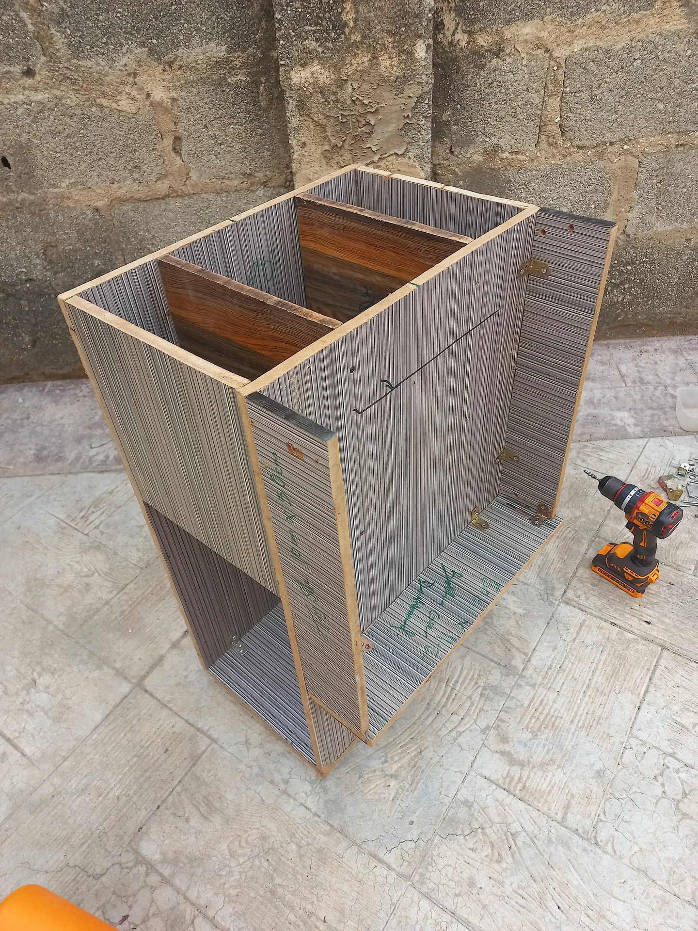
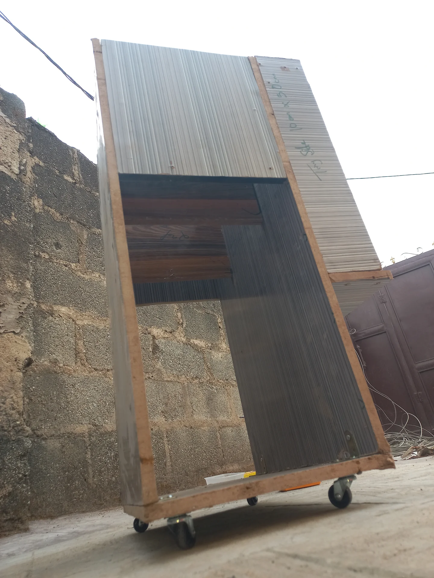
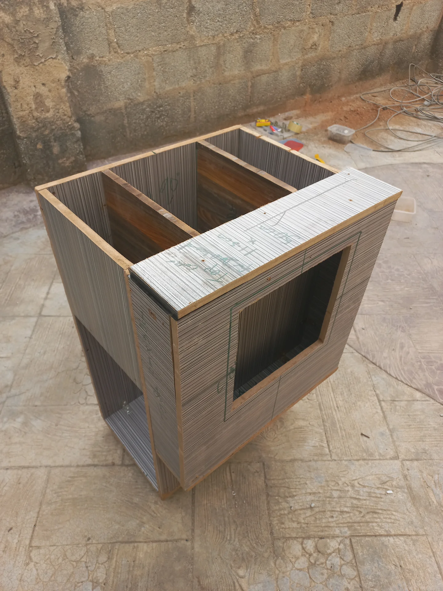
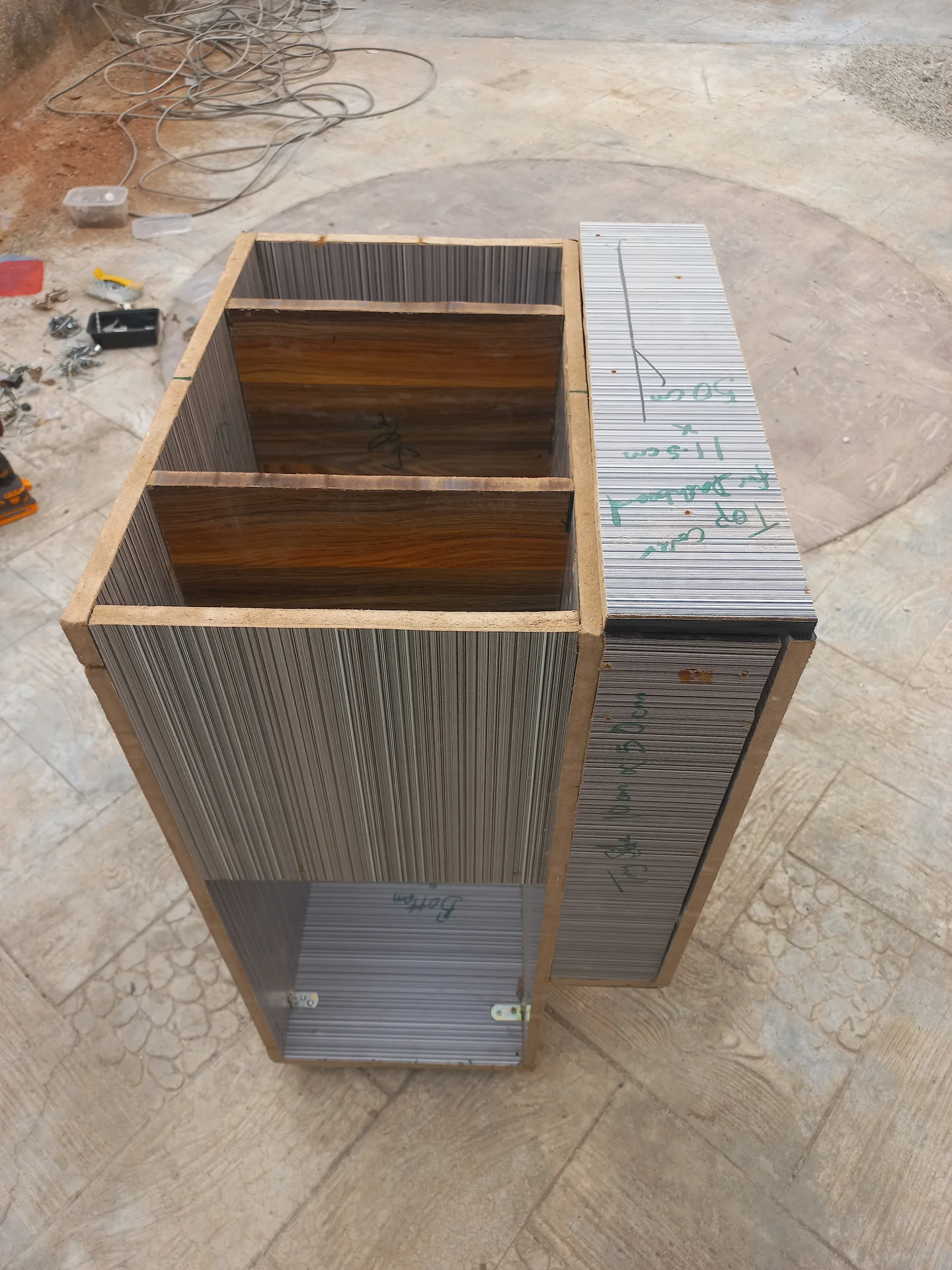
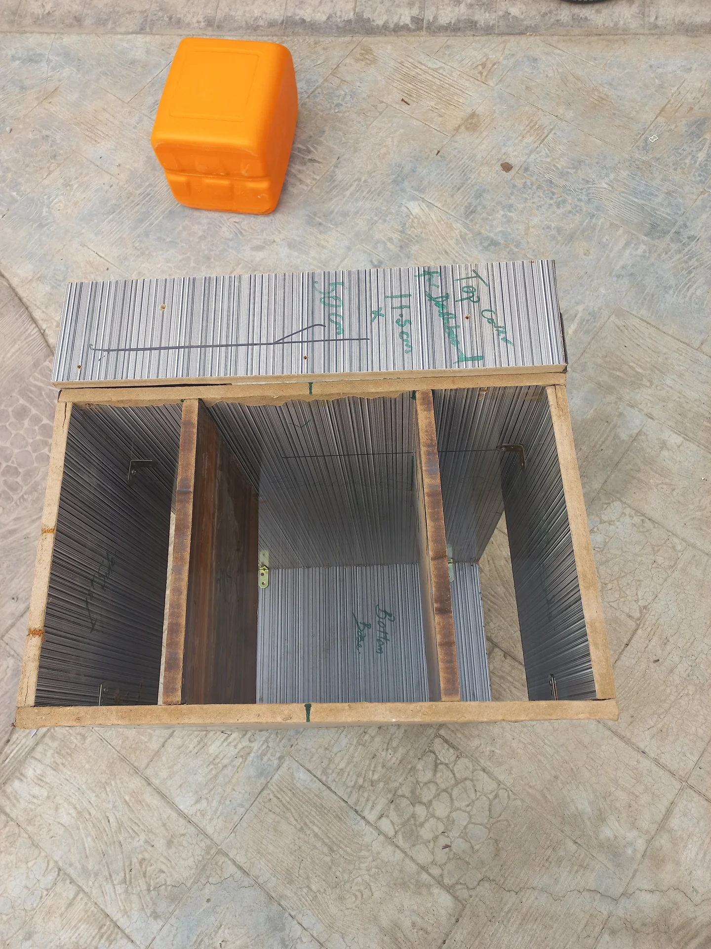
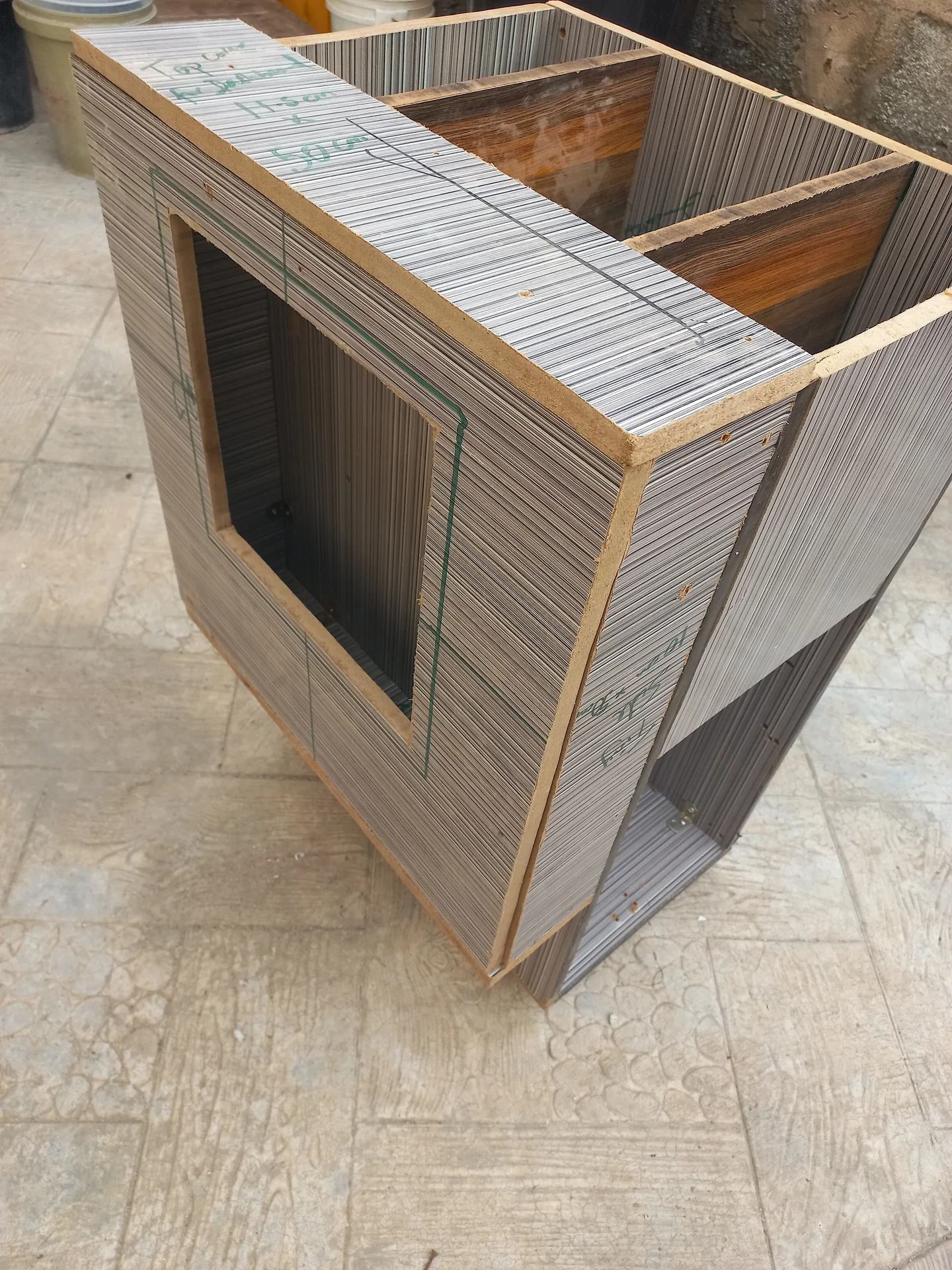
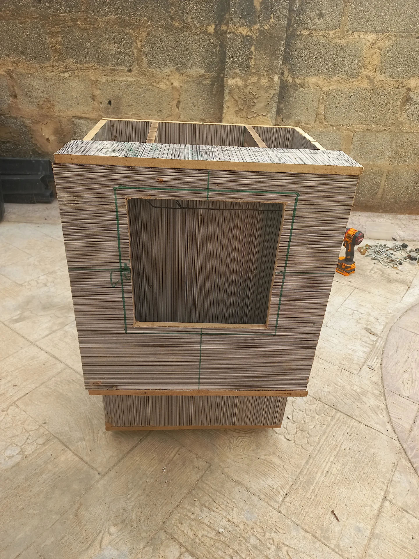
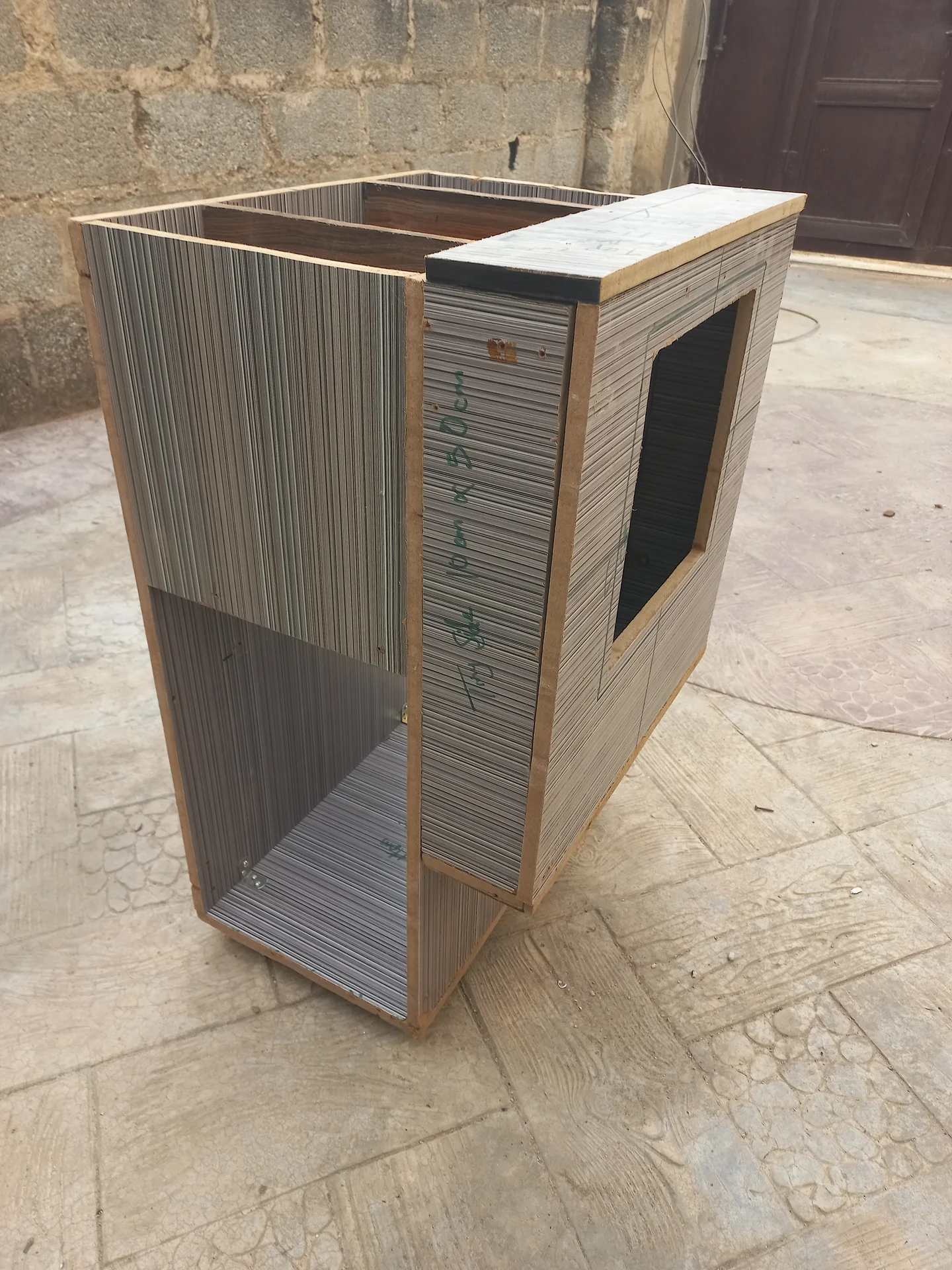
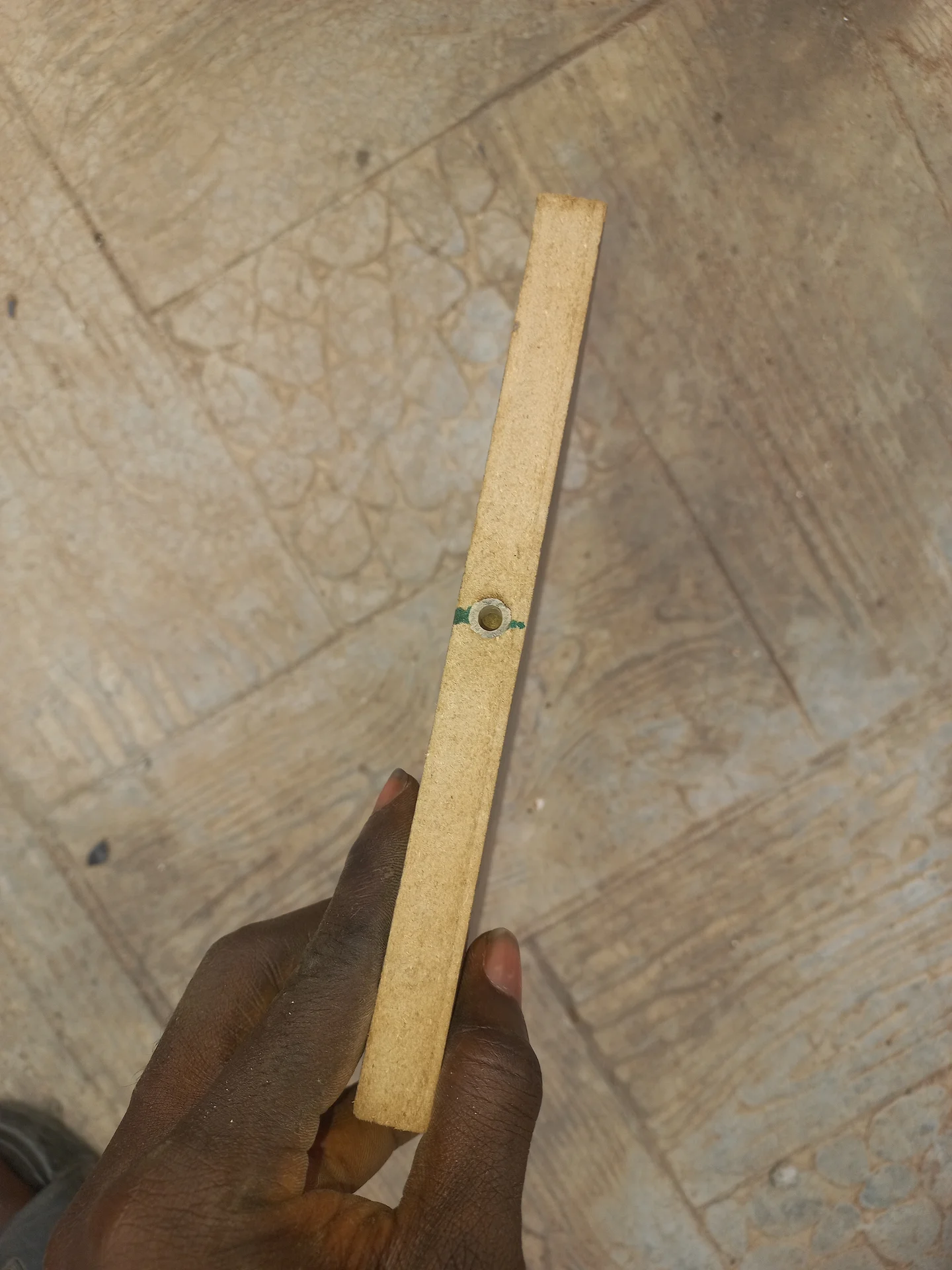
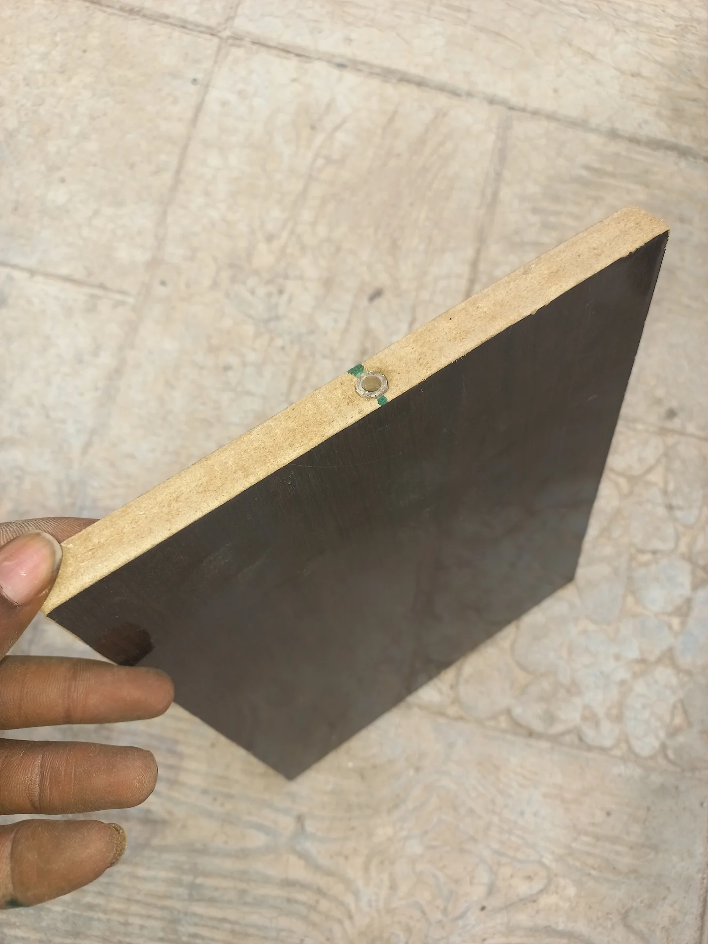
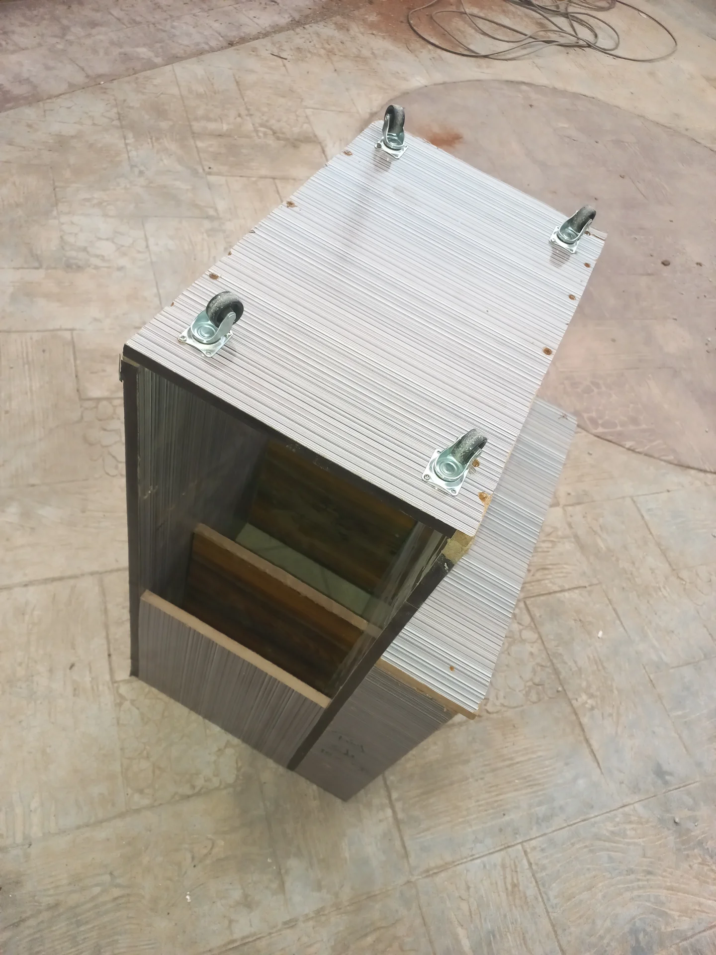
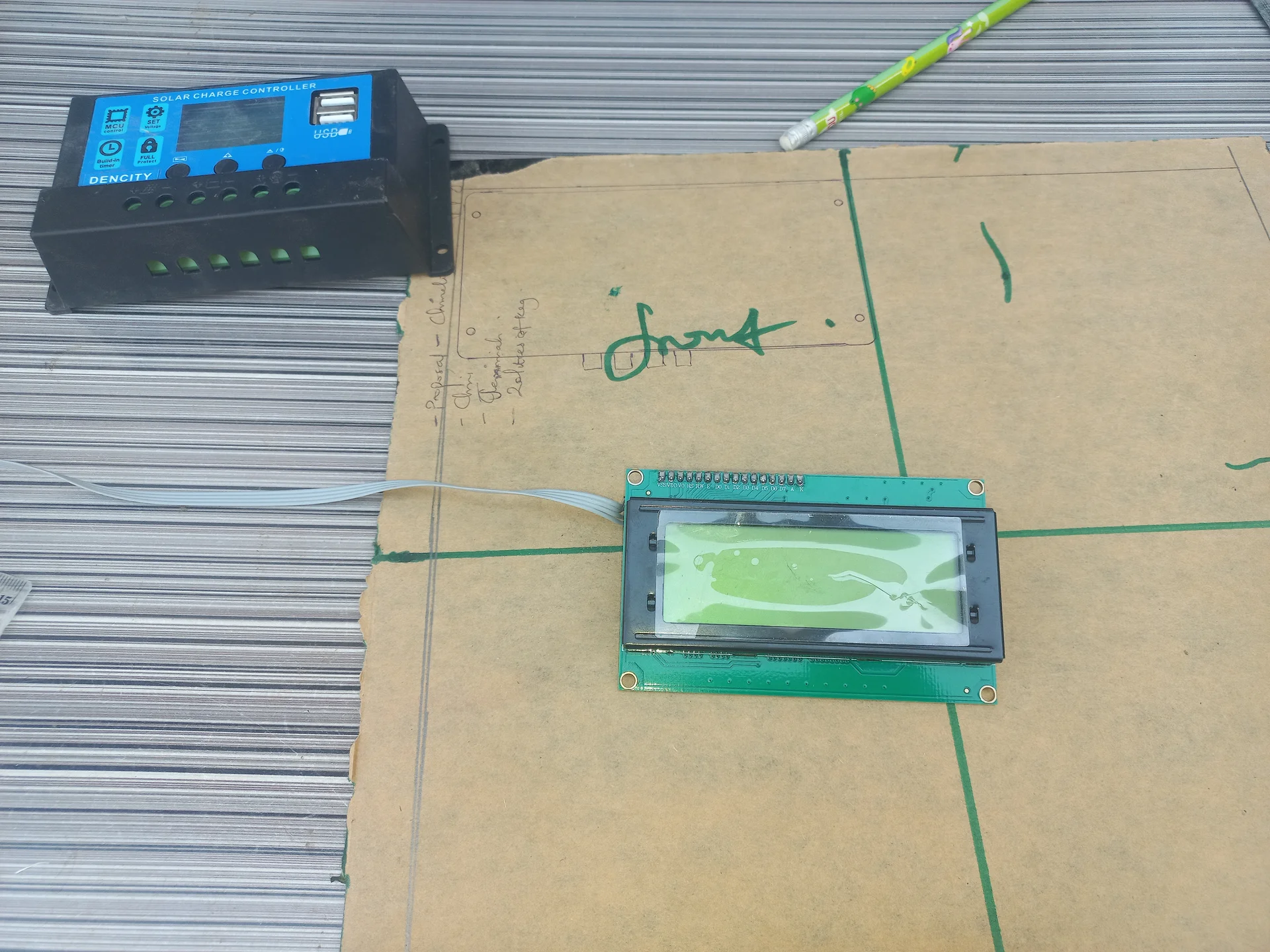
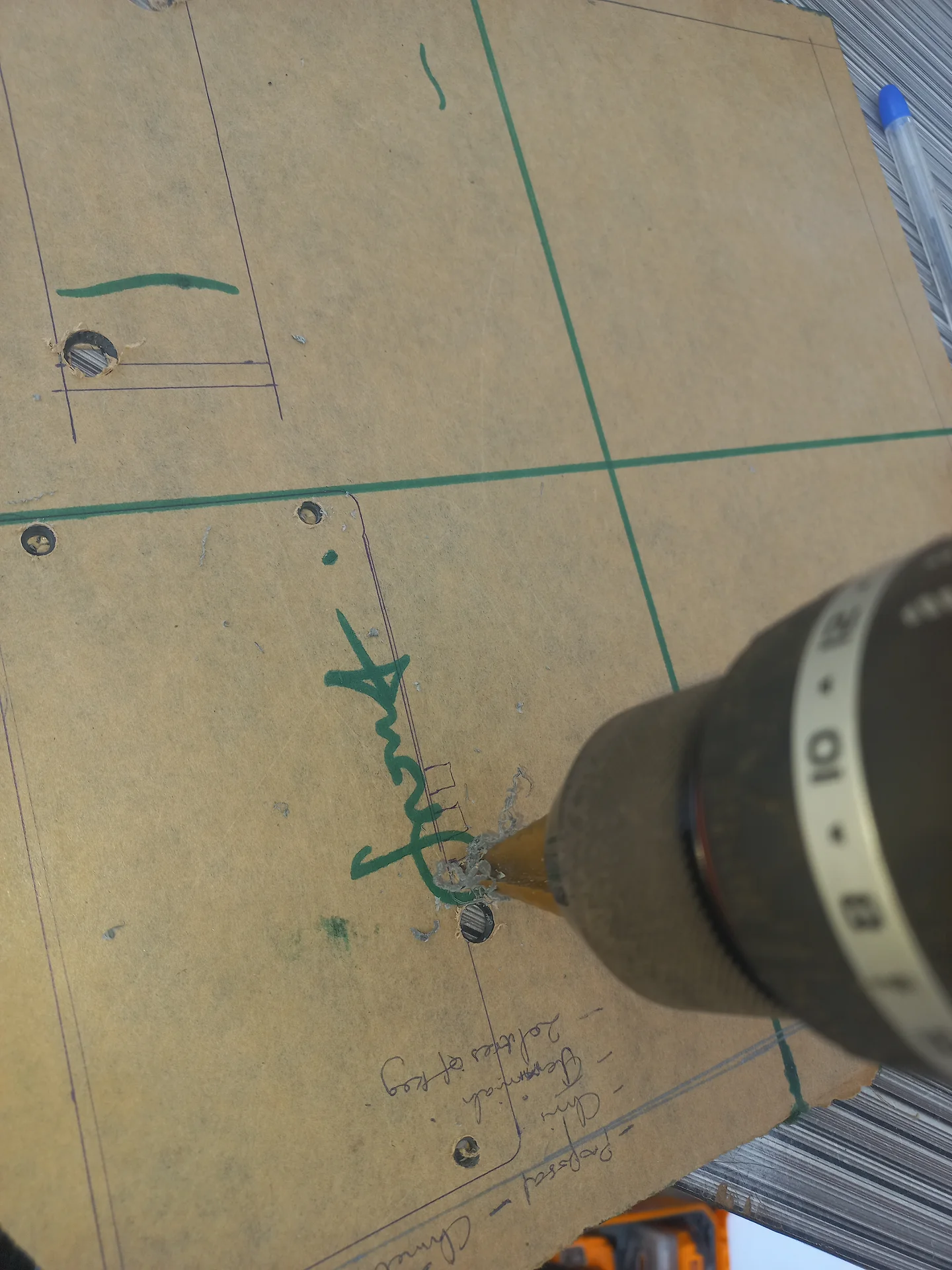
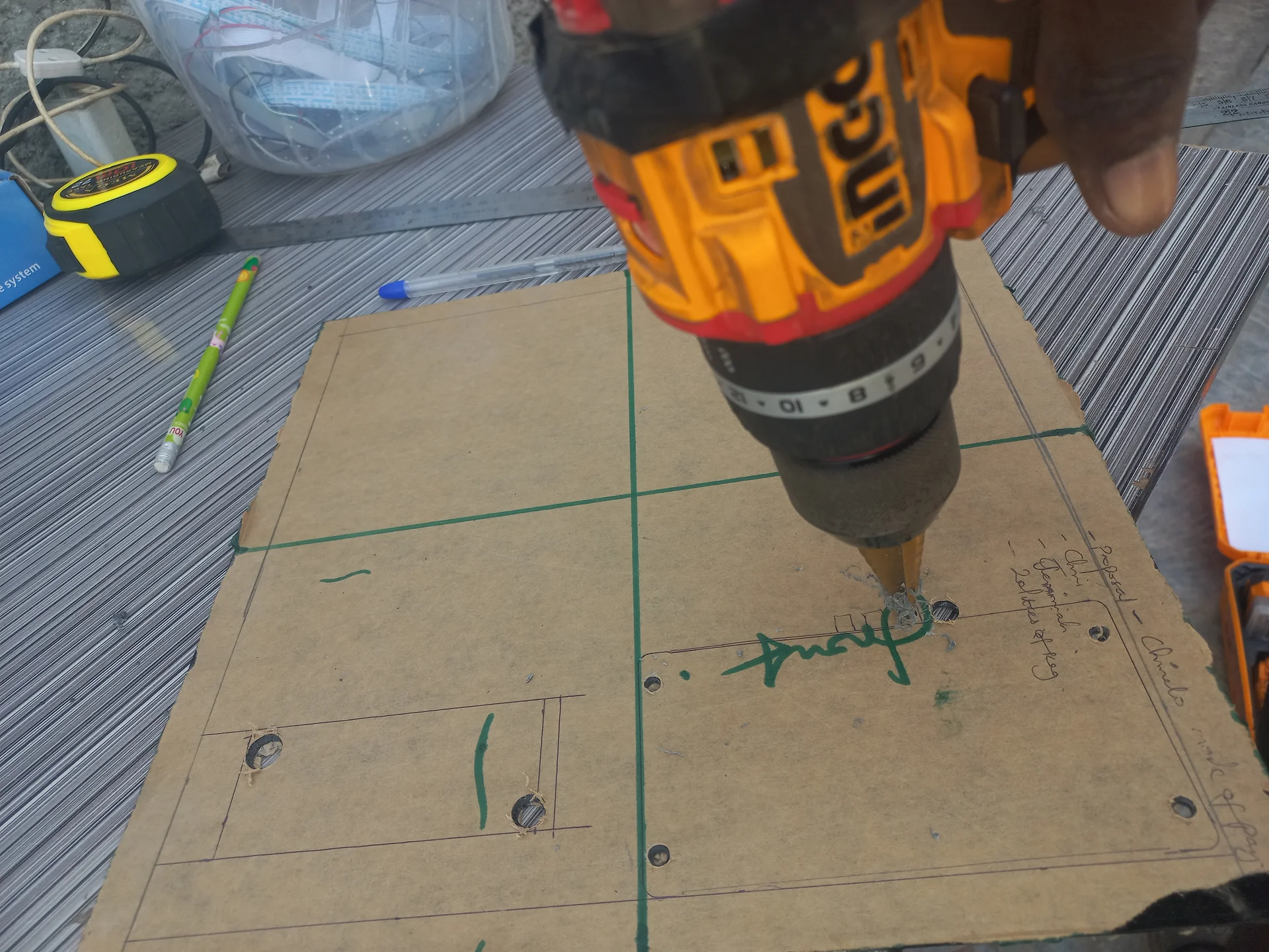
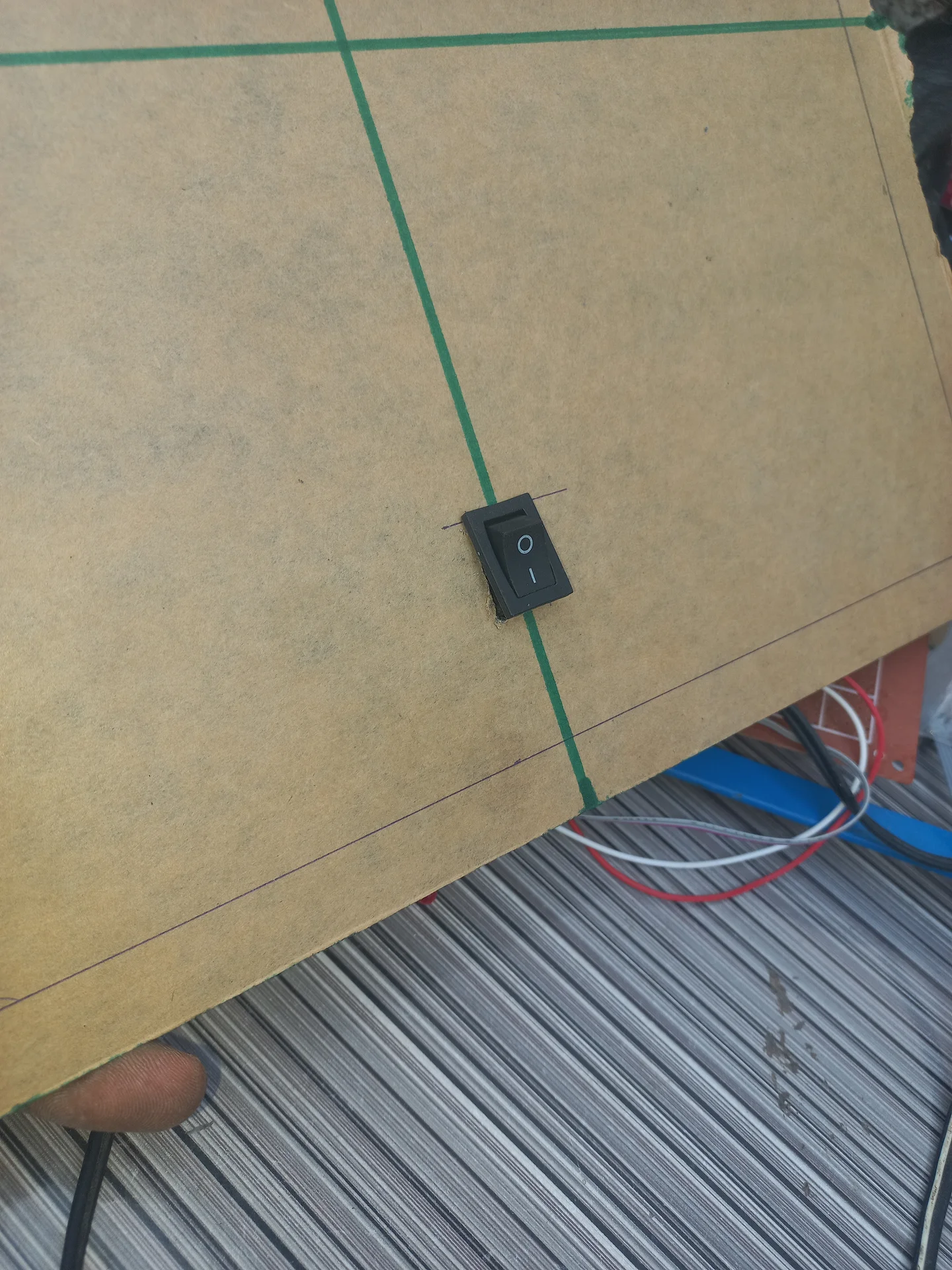
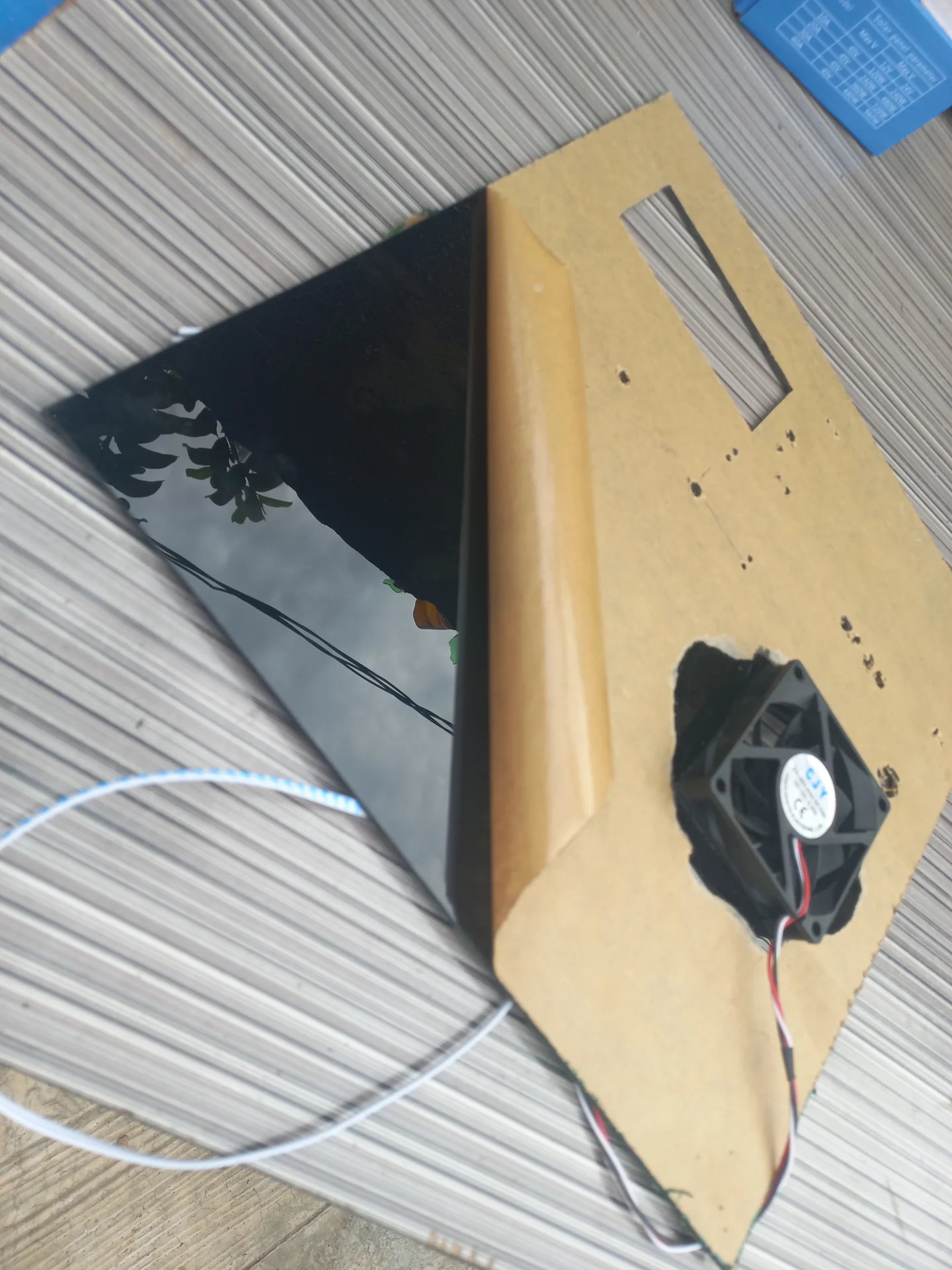
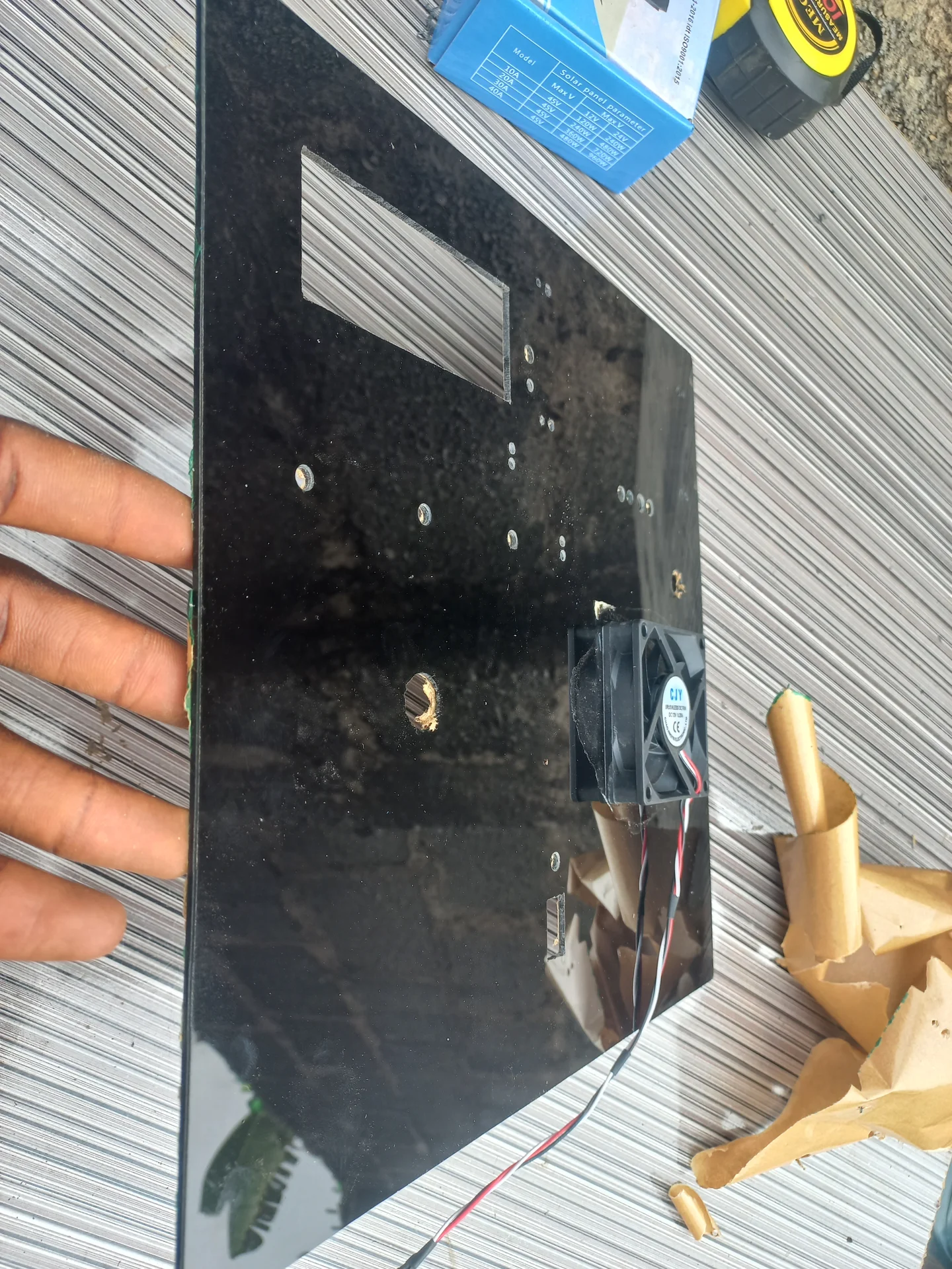
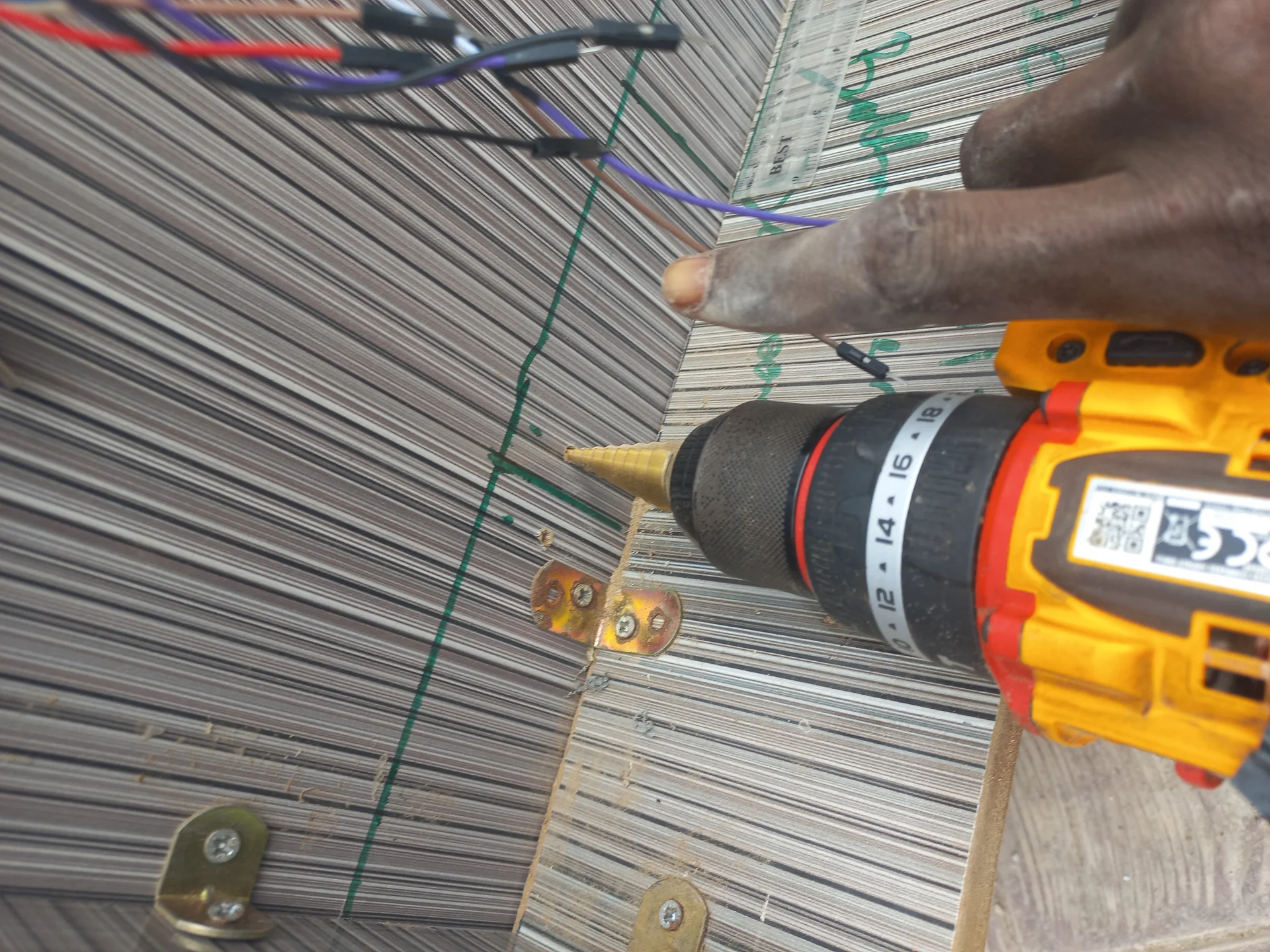
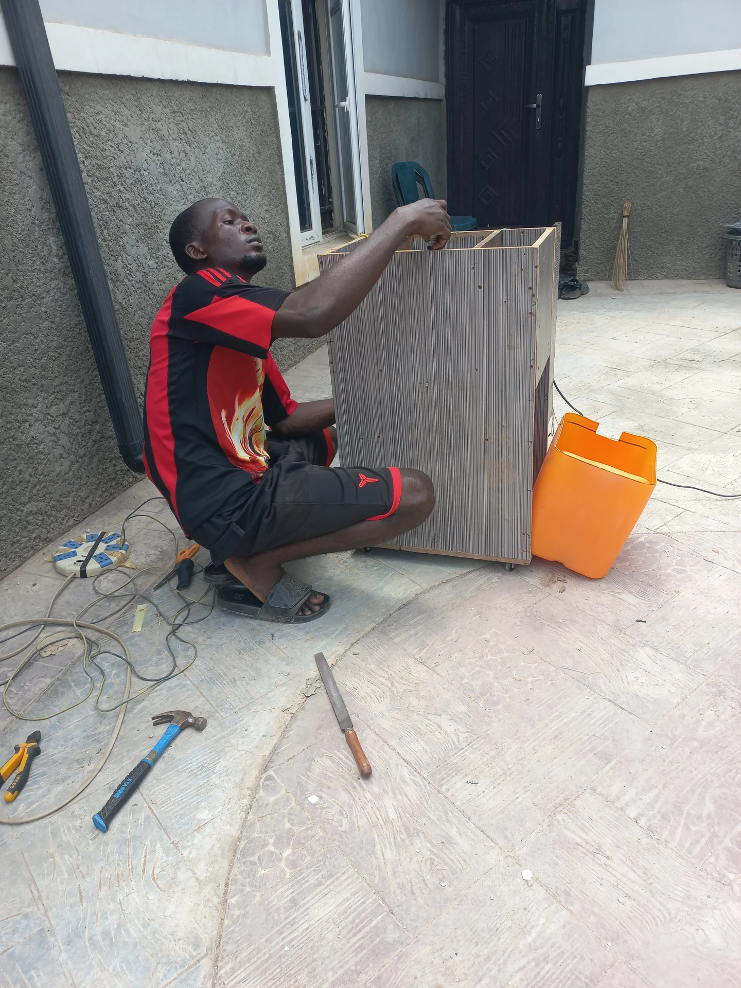
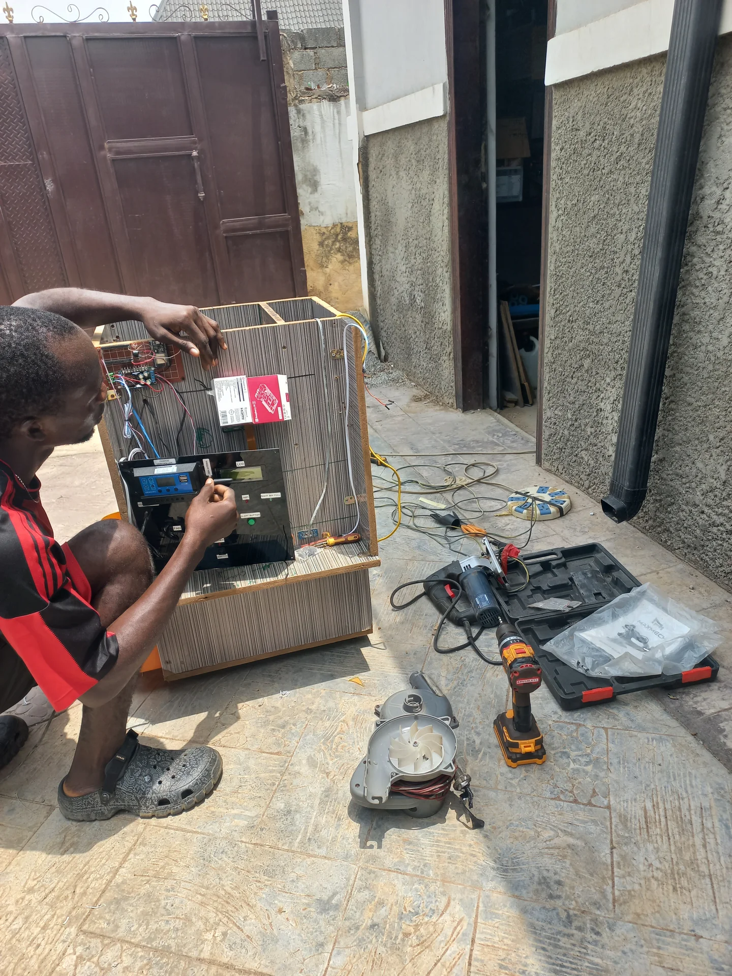
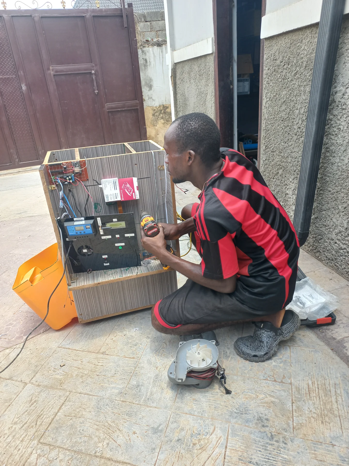
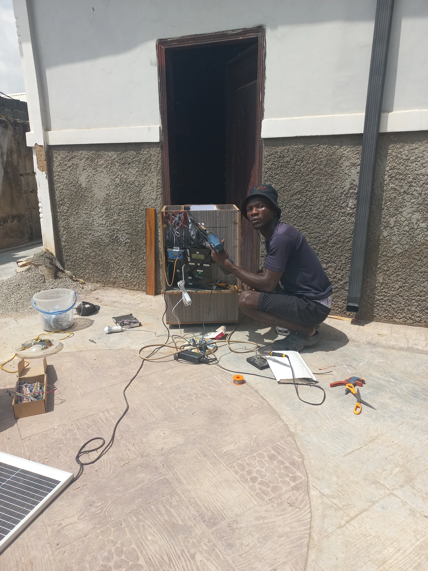
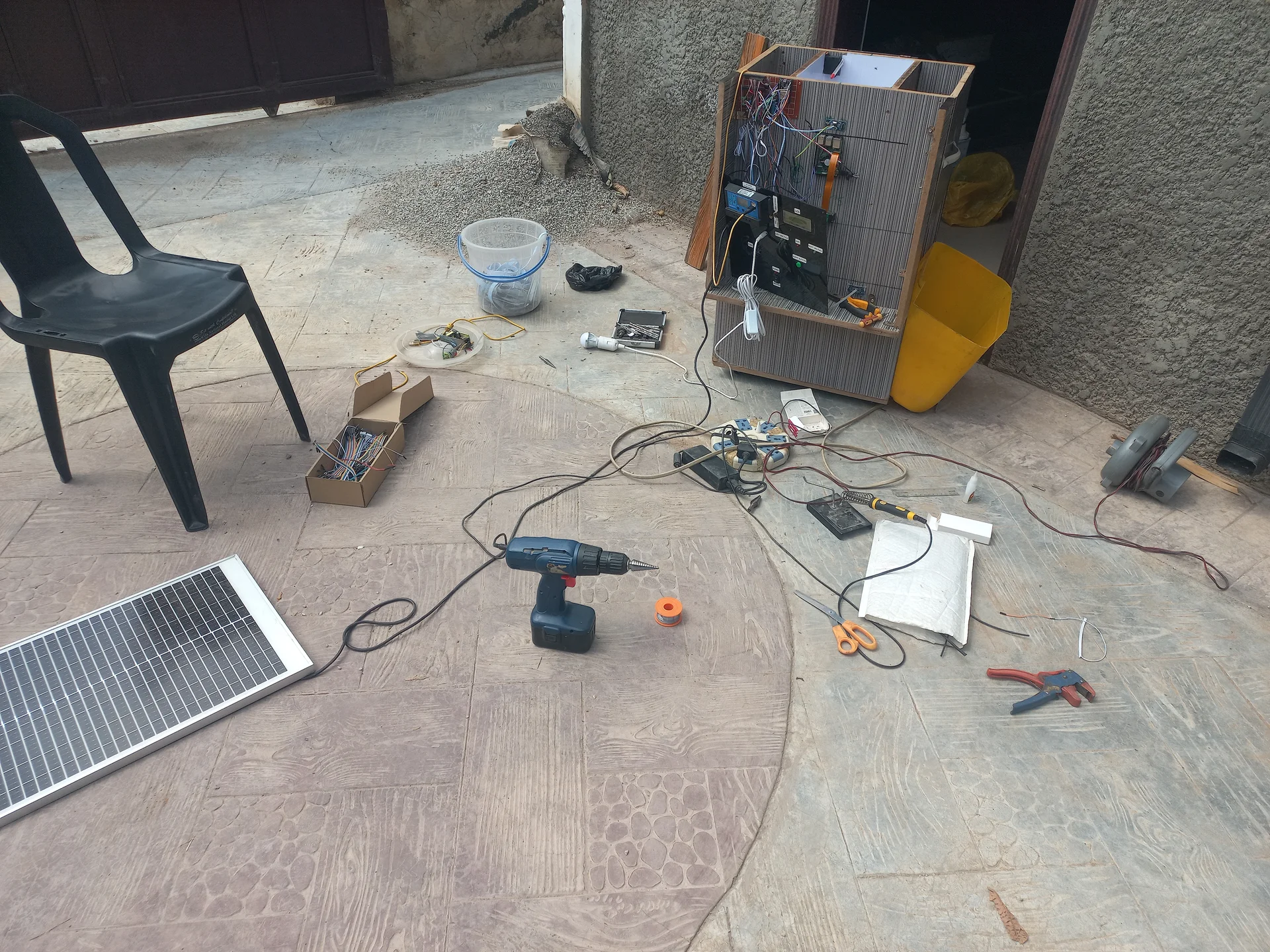
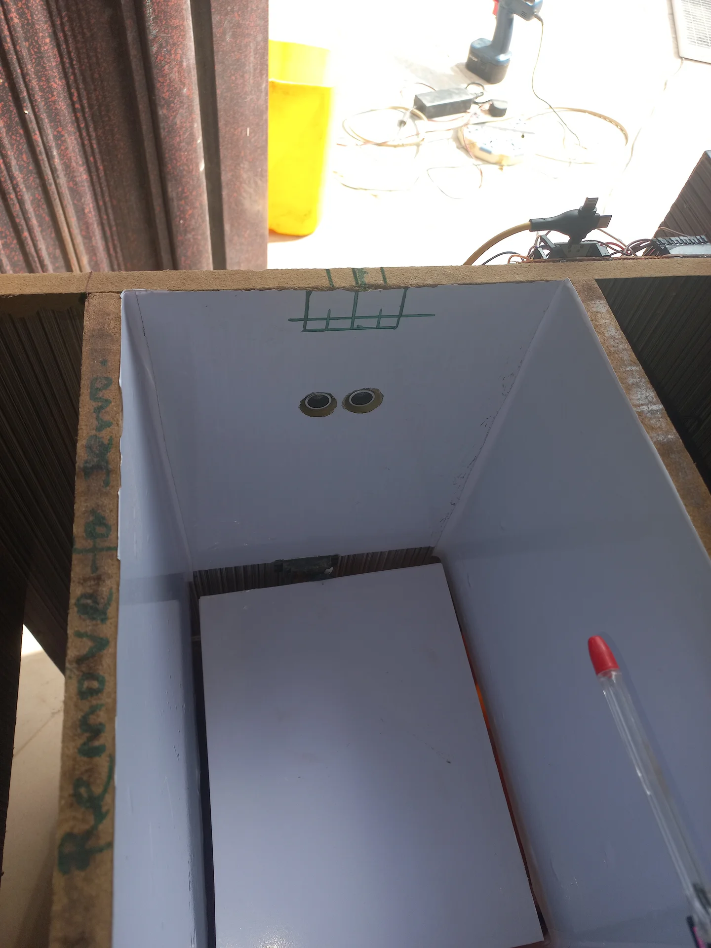
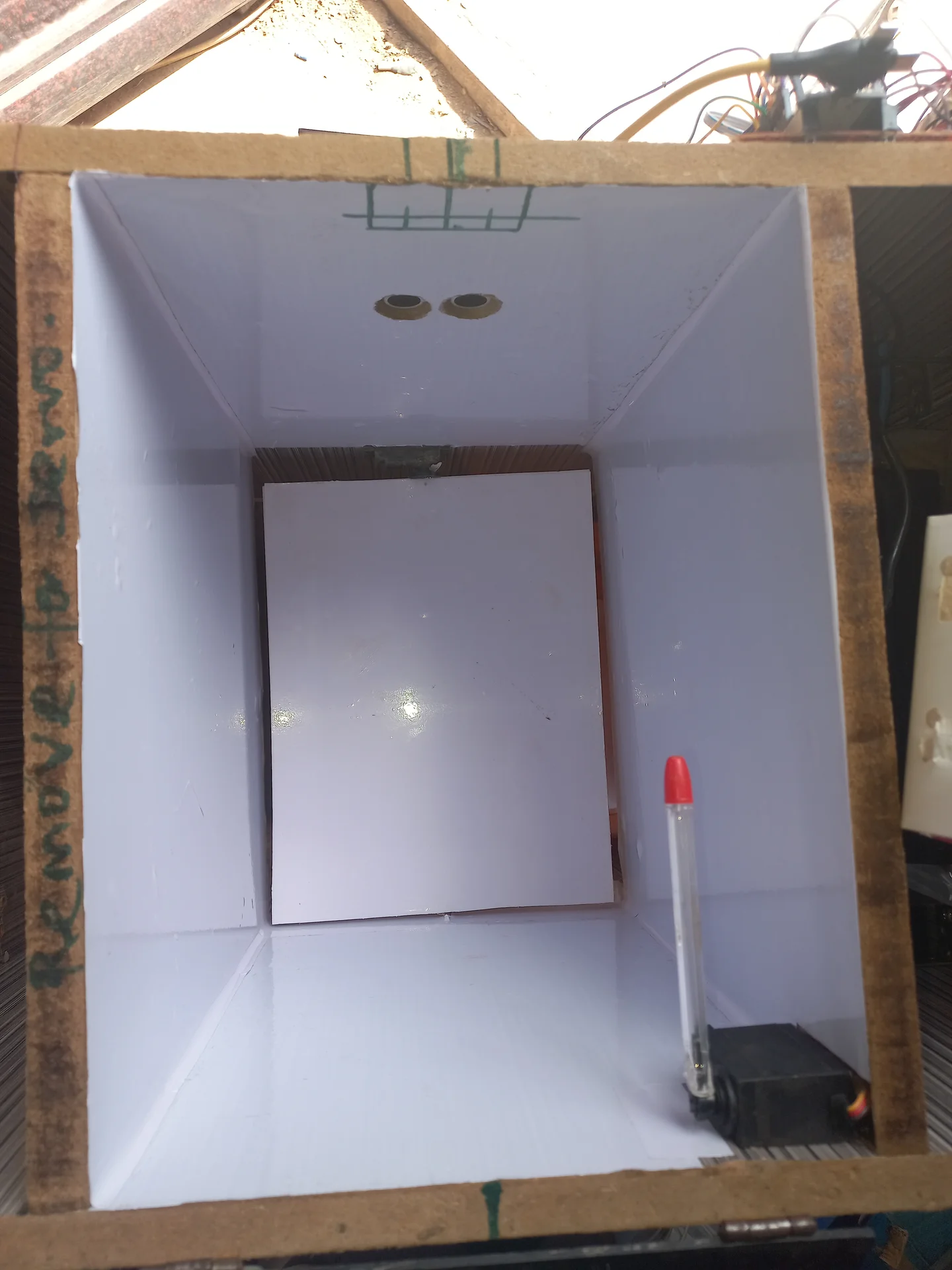
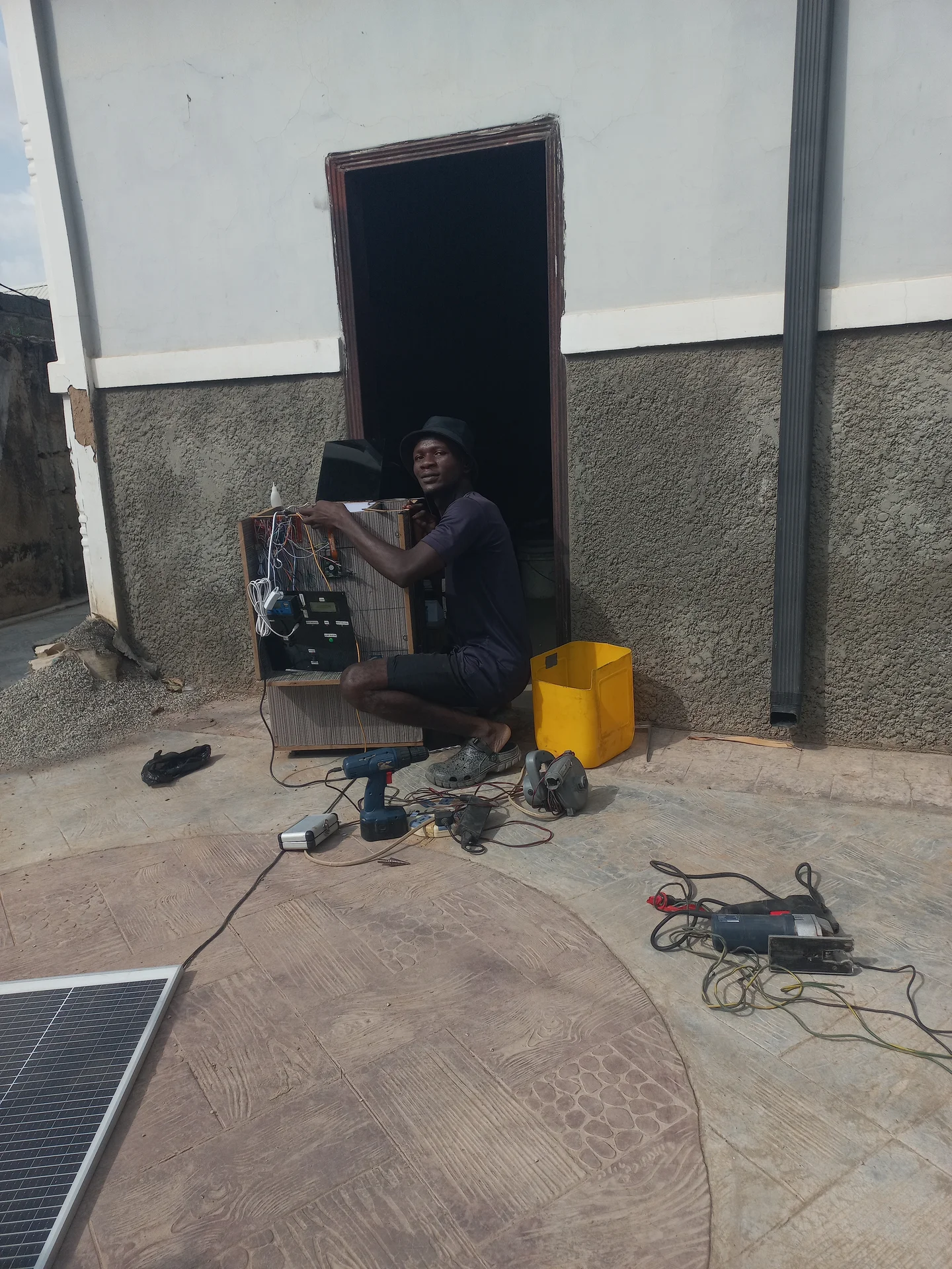
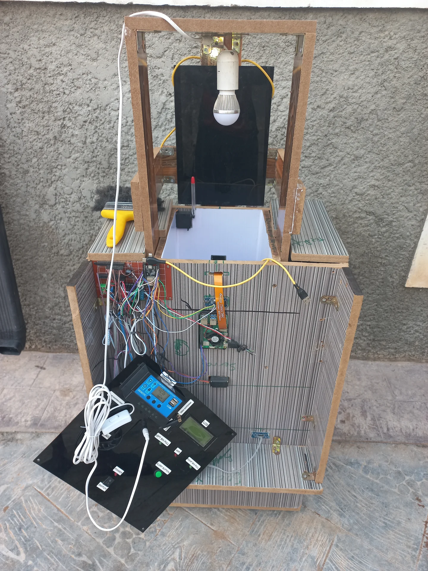
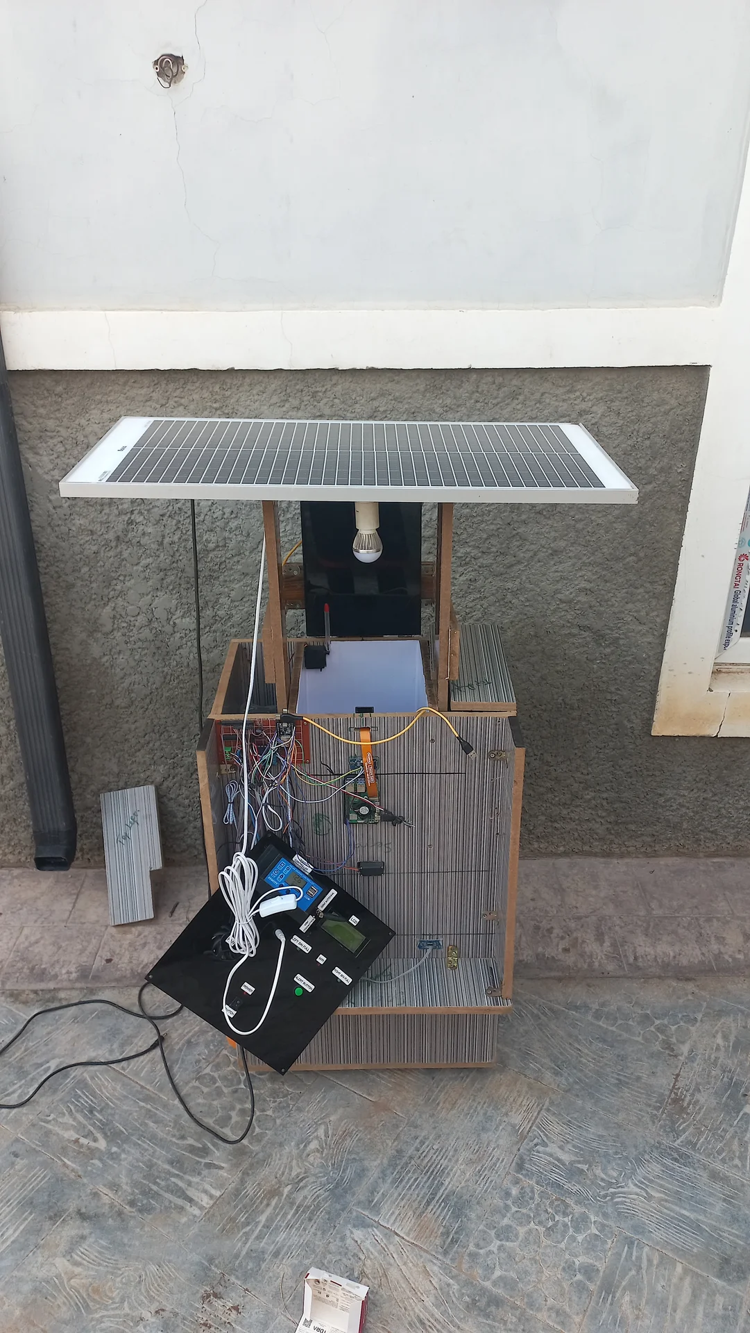
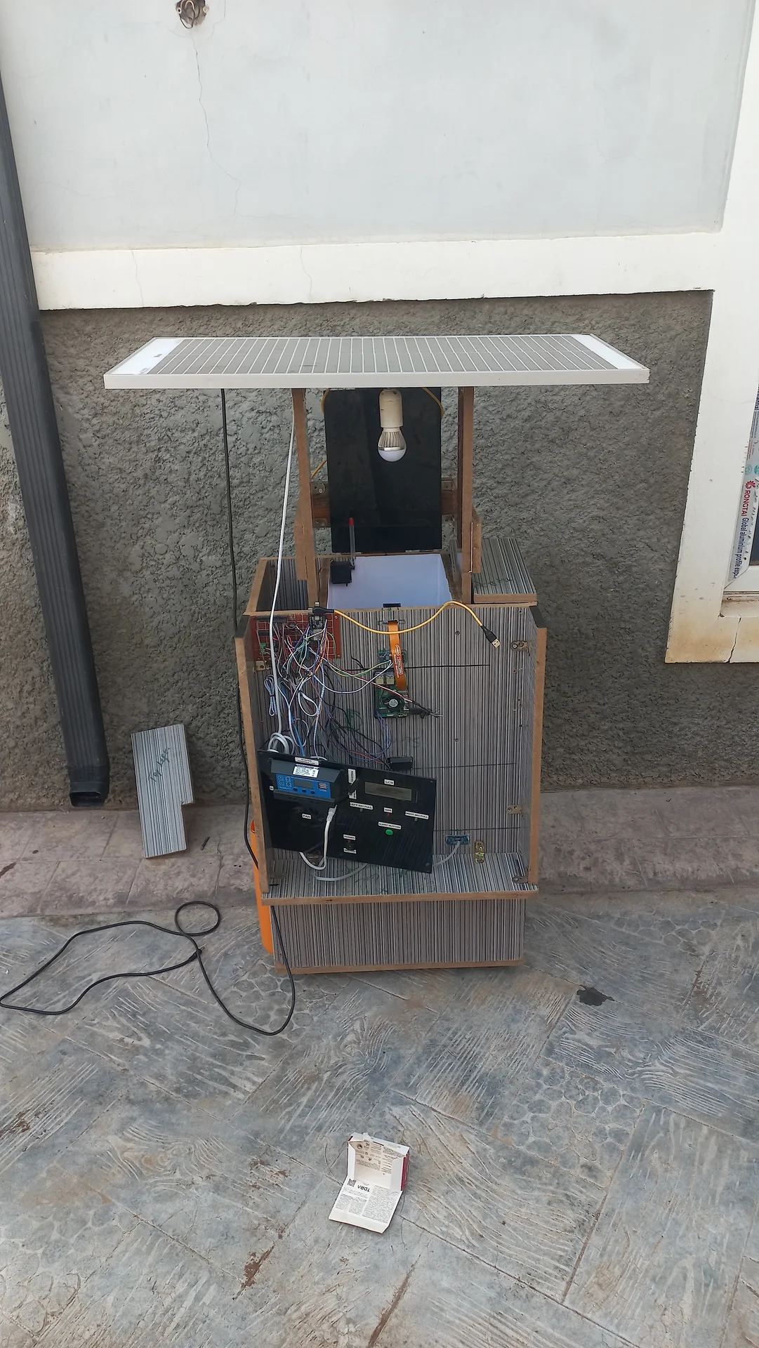
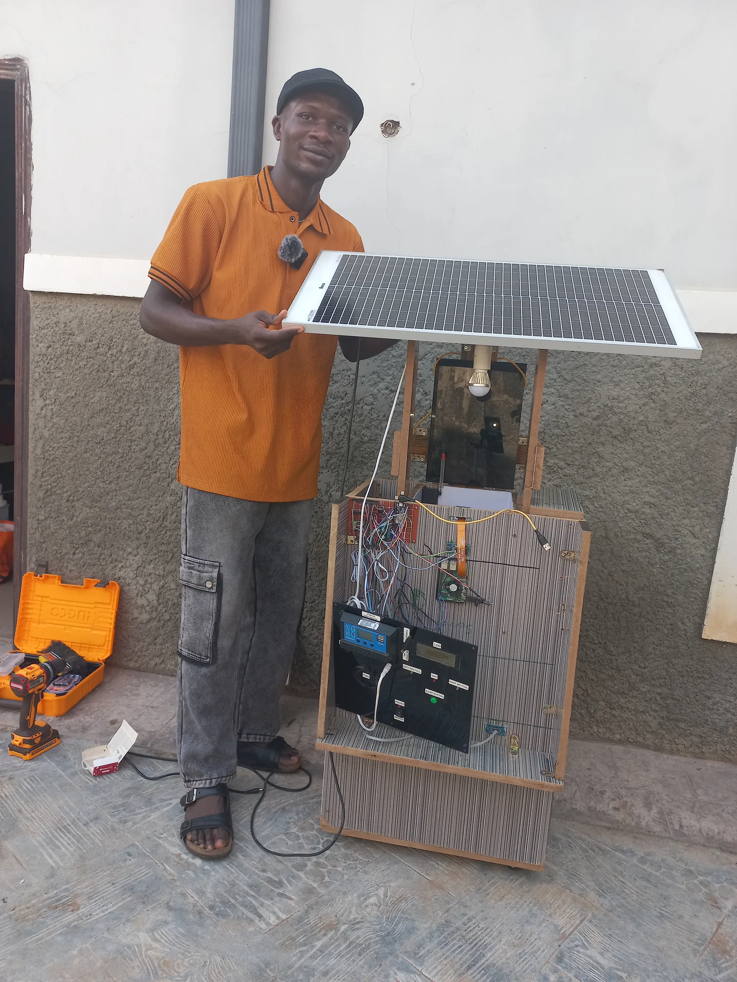
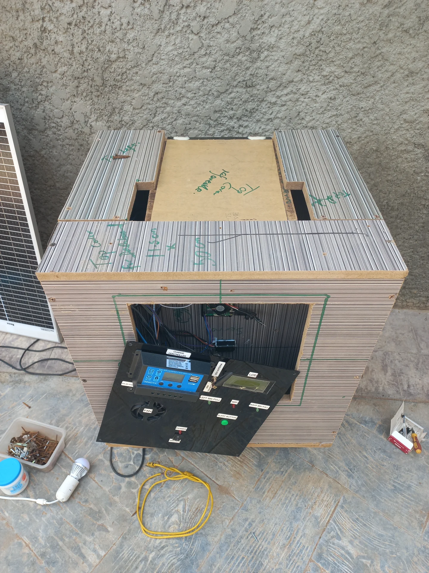
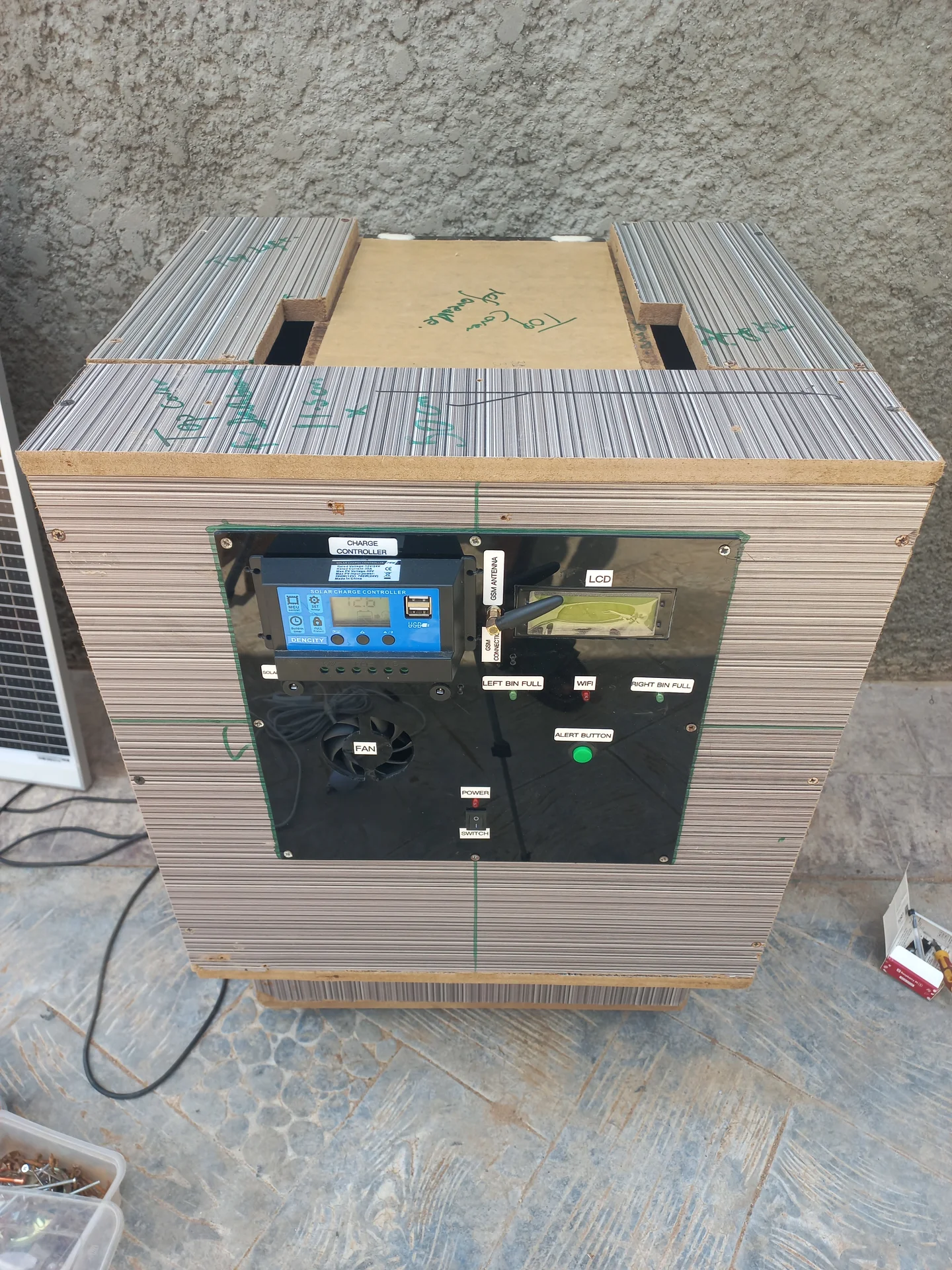
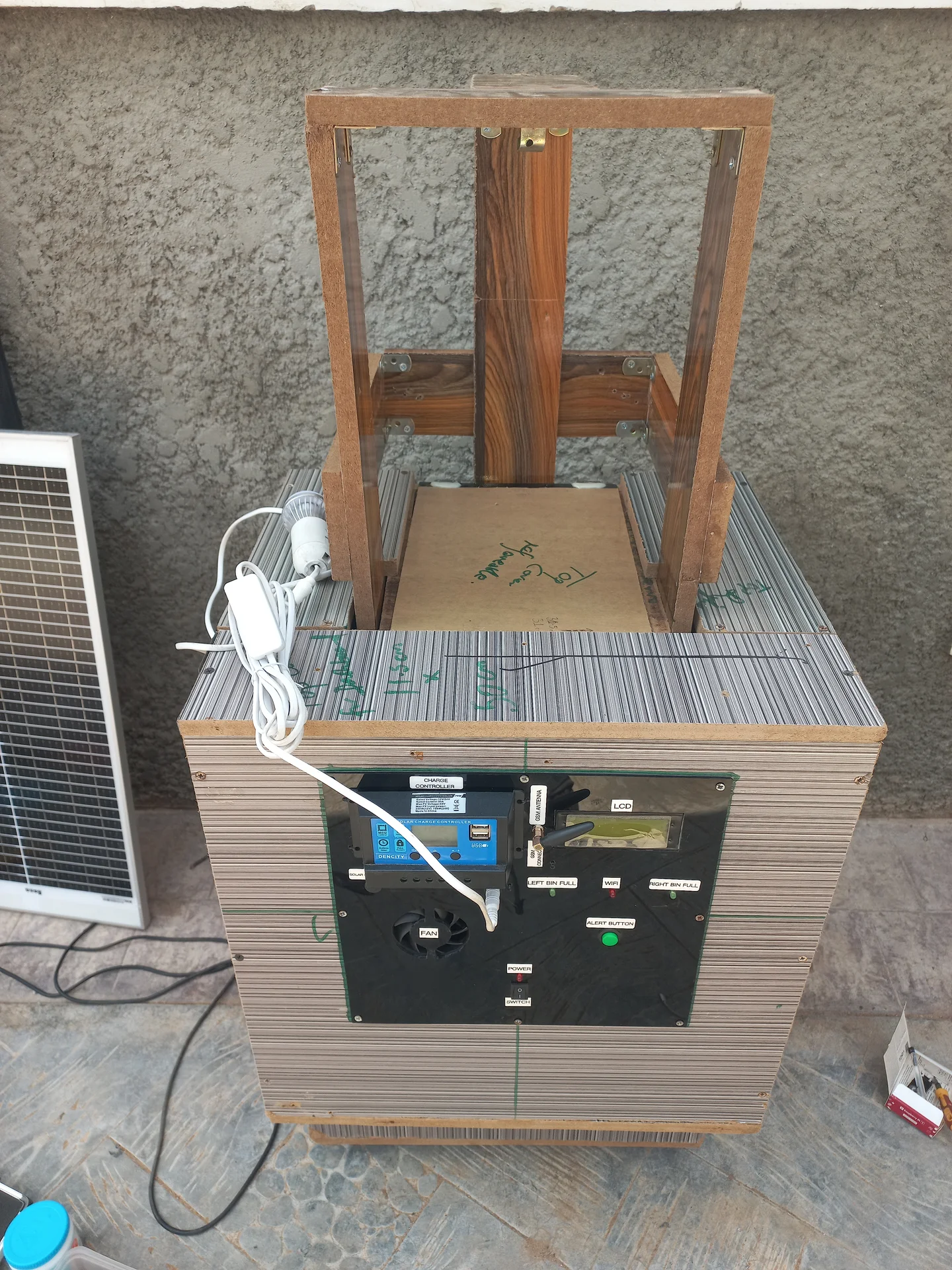
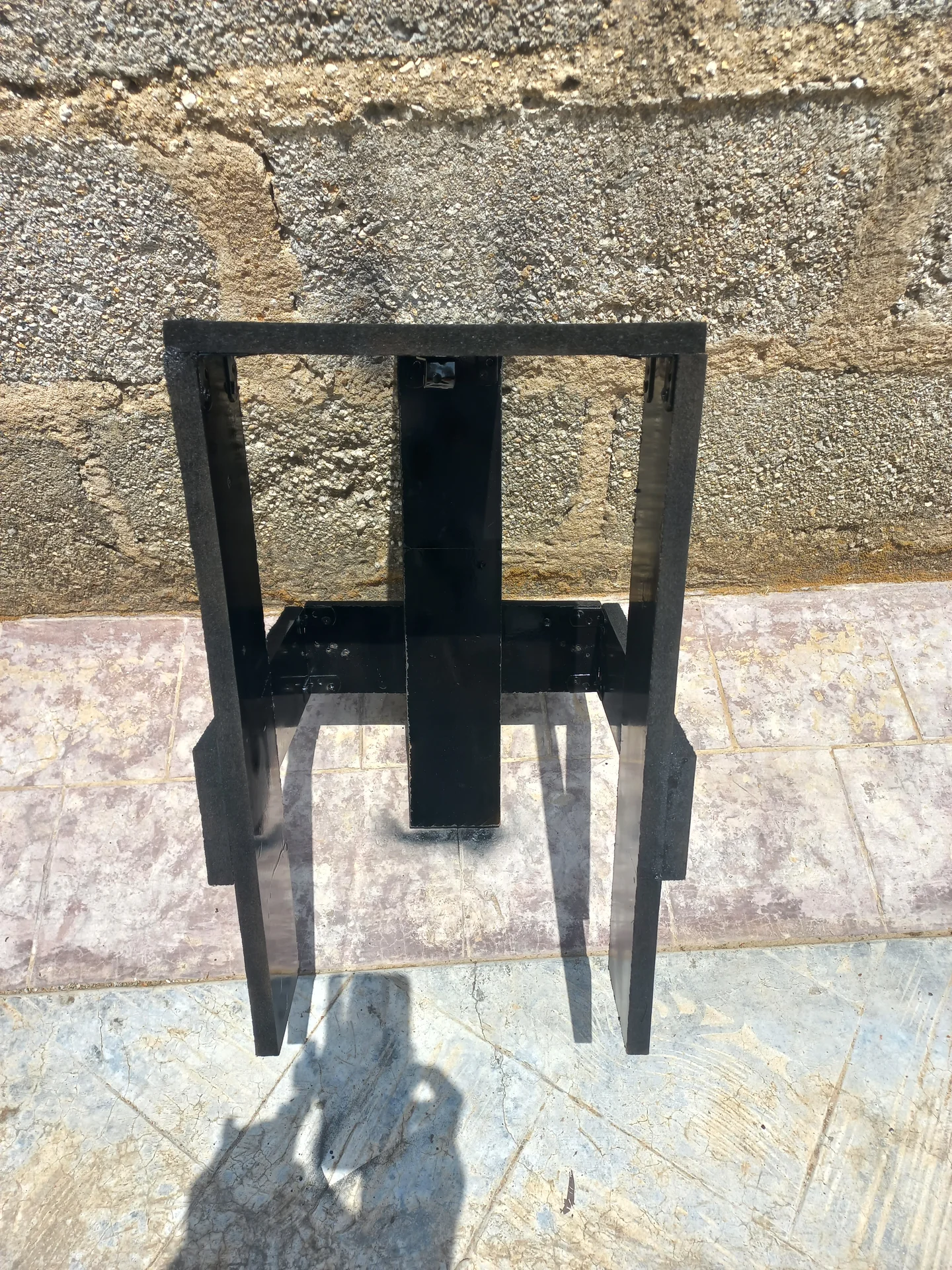
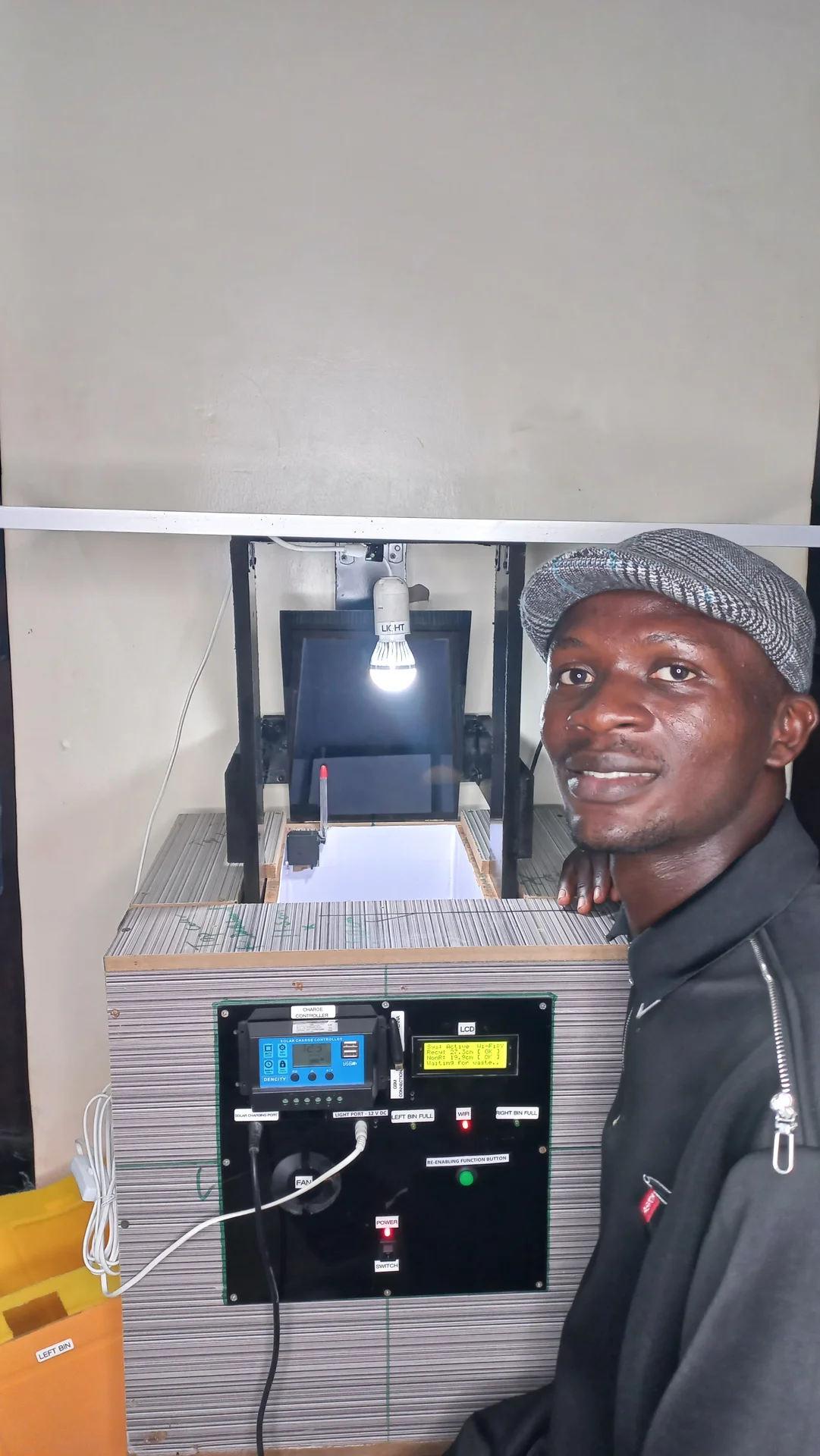
Documentation of the full build from day one procurement through to the completed, powered-on system.


YouTube Demo, coming soon
A full walk-through of the sorting system in action will be uploaded to YouTube.
I sincerely appreciate you taking the time to explore my portfolio and learn about my work and expertise. If you have any questions or wish to discuss potential collaborations, please feel free to reach out via the Contact section.
Best regards,
Damilare Lekan, Adekeye.