3-Phase Power Protection System for Industrial X-Ray Machine
Multi-Layered Electrical Protection Panel featuring Schneider Electric 250A Contactor, iPRU 65 Surge Arrester, CHINT XJ3-D Voltage Monitoring Relay, and ENTES MK-01 Phase Failure Relay
Introduction
This project documents the design and construction of a dedicated 3-phase power protection panel engineered to safeguard a high-value industrial X-ray machine from electrical power anomalies. X-ray machines are highly sensitive medical/industrial equipment that require clean, stable 3-phase power to operate reliably. Power disturbances such as phase failure, voltage surges, overvoltage, undervoltage, and phase sequence errors can cause catastrophic damage to the X-ray tube, high-voltage transformer, and control electronics — repairs that are extremely costly.
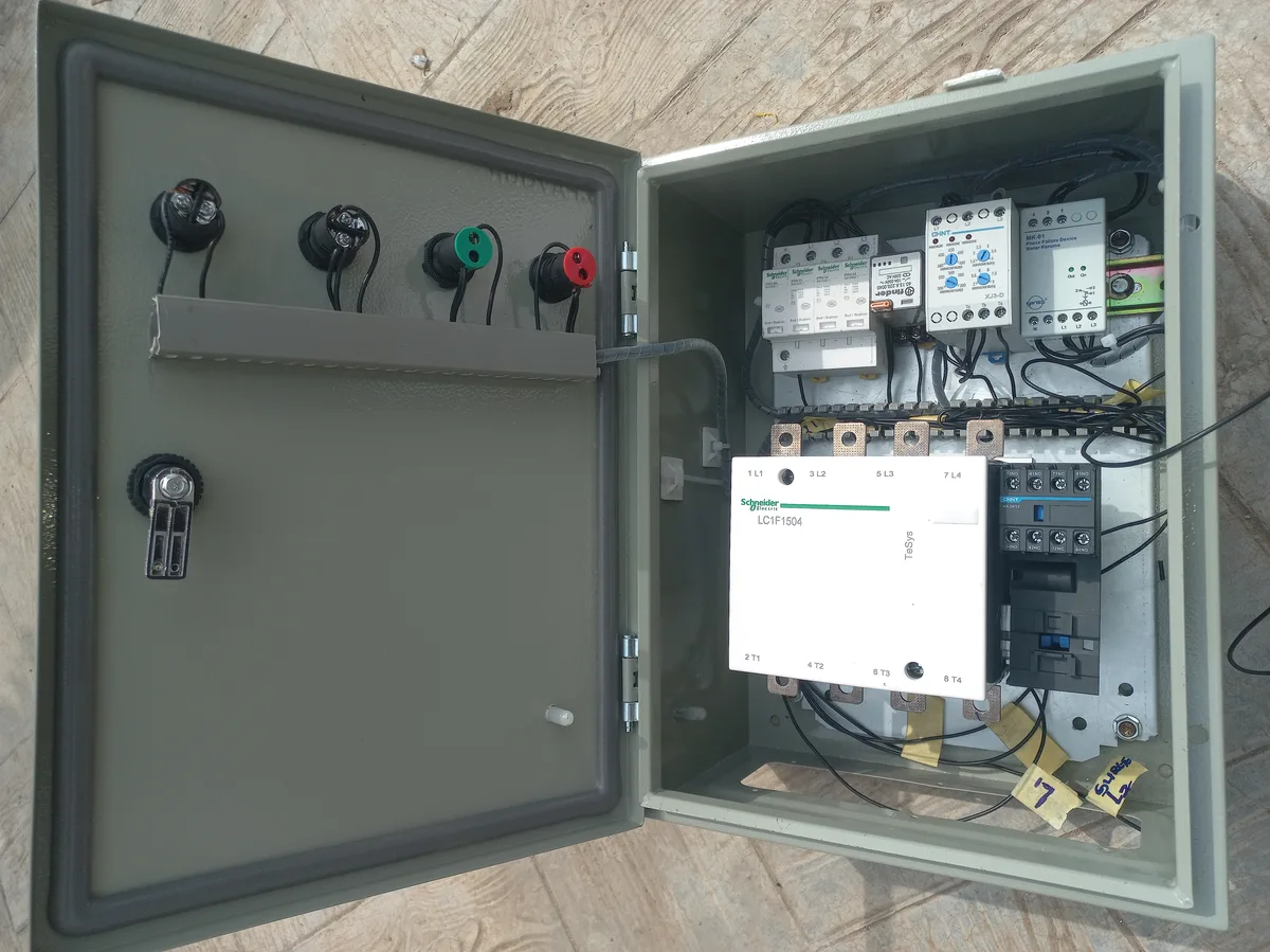
The protection system integrates multiple layers of defence: a Schneider Electric iPRU 65 modular surge arrester (3P+N, Type 2) for transient voltage suppression, a CHINT XJ3-D phase failure and voltage monitoring relay with adjustable overvoltage/undervoltage thresholds and time delays, an ENTES MK-01 phase failure relay for motor-grade phase sequence protection, a Schneider Electric 250A 3-phase AC contactor for main power switching, and a Finder 60.13.8.220.0040 plug-in relay for control circuit logic. All components are DIN-rail mounted inside a metal enclosure with organized cable management.
Aim and Objectives
The primary aim of this project is to design and build a robust electrical protection panel that shields an industrial X-ray machine from all common 3-phase power anomalies, thereby preventing equipment damage, extending the machine's operational lifespan, and ensuring operator safety.
- Phase Failure Protection: Detect and disconnect power within milliseconds if any of the three phases is lost, preventing single-phasing damage to motors and transformers.
- Overvoltage Protection: Monitor all three phases and trip the contactor if voltage exceeds the adjustable upper threshold (up to 460V), protecting sensitive X-ray electronics.
- Undervoltage Protection: Trip on low voltage conditions (adjustable down to 300V) to prevent the X-ray machine from operating outside safe voltage range.
- Surge Suppression: Clamp transient overvoltages (lightning, switching surges) to safe levels using a Type 2 surge protective device rated at 65kA.
- Phase Sequence Verification: Ensure correct L1-L2-L3 phase rotation before allowing the machine to energise, preventing reverse rotation of any motor-driven components.
- Controlled Power Switching: Use a 250A electromagnetic contactor for reliable make/break of the main 3-phase supply under load.
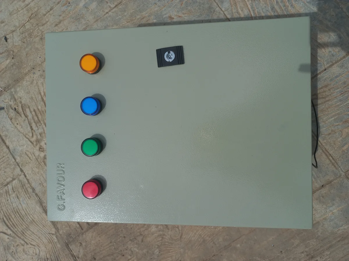
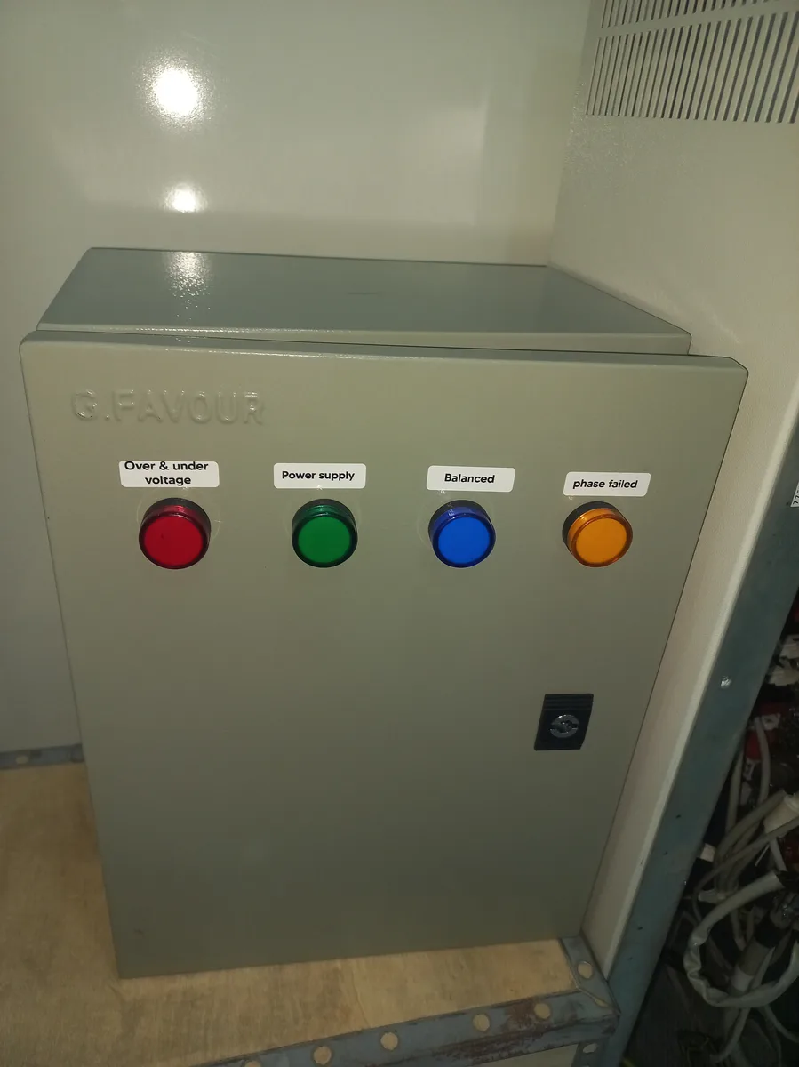
- Visual Status Indication: Provide clear LED indicators (Red, Amber, Blue, Green) for power status, fault conditions, and system readiness.
Components & Specifications
Every component was selected for industrial reliability and compatibility with the 3-phase 380–415V supply. Below is the verified list of all components used in the protection panel, with their correct specifications.
Protection Devices
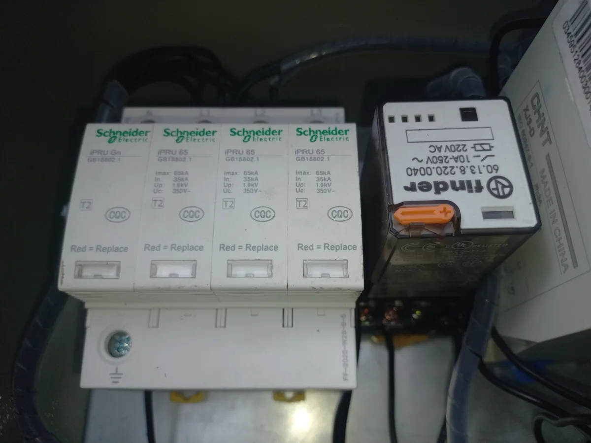
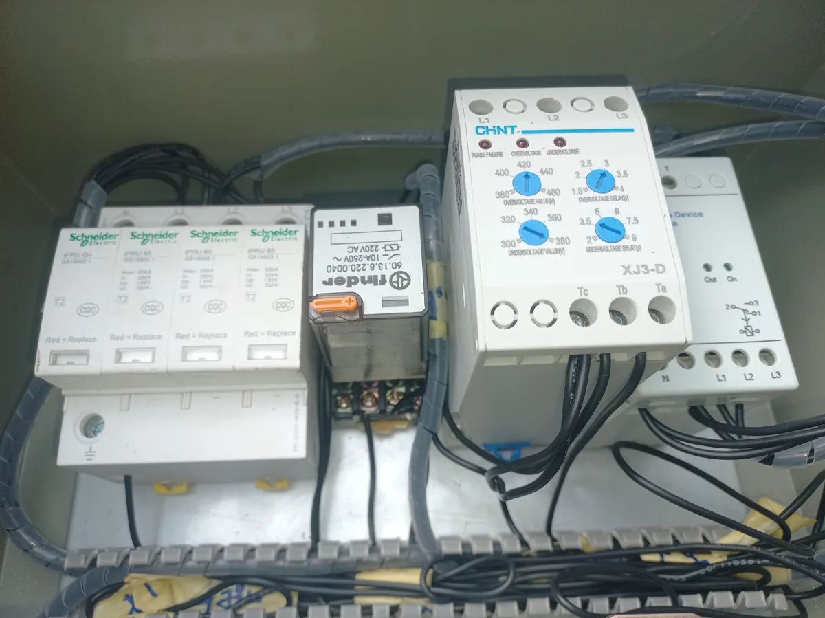
- Schneider Electric iPRU 65 Modular Surge Arrester (A9L65601) — 3P+N, Type 2 (T2), Imax 65kA, In 35kA, Up 1.9kV, Uc 350V~. Features visual "Red = Replace" status indicators on each module. CQC certified. Protects against lightning-induced and switching transient overvoltages.
- CHINT XJ3-D Phase Failure & Voltage Monitoring Relay — Adjustable overvoltage threshold (300–460V), adjustable undervoltage threshold (300–380V), adjustable time delays for both OV and UV. Detects phase failure, overvoltage, and undervoltage conditions. Connections: L1, L2, L3 inputs; Tc, Tb, Ta output contacts.
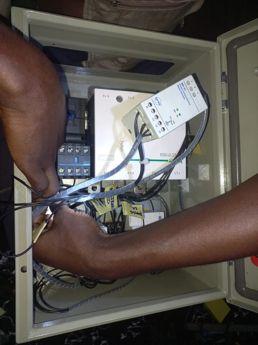
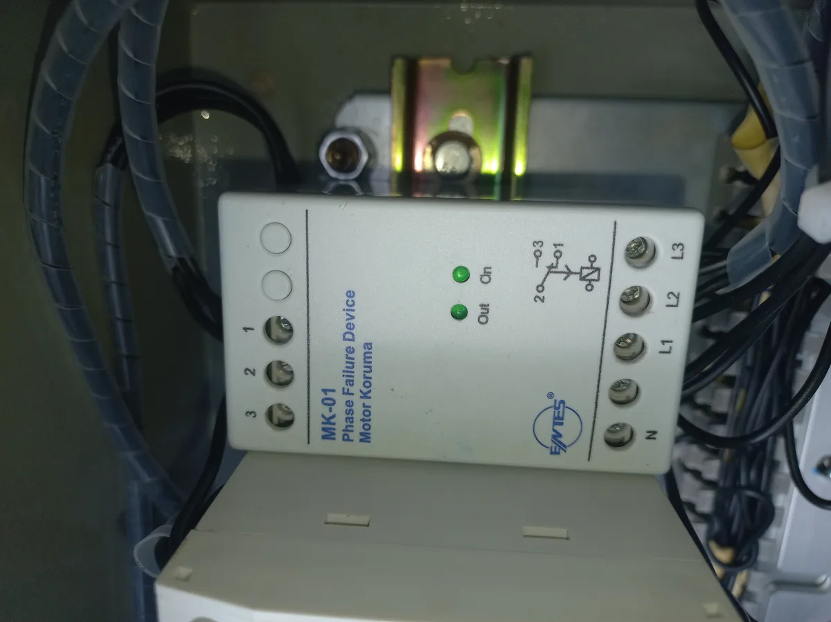
- ENTES MK-01 Phase Failure Relay — Motor protection grade, 220–230 VAC operating range, DIN2 rail mounting, 1 C/O changeover contact, 8A / 2000VA contact output, 20% fixed asymmetry detection. Provides redundant phase failure protection alongside the CHINT relay.
Switching & Control
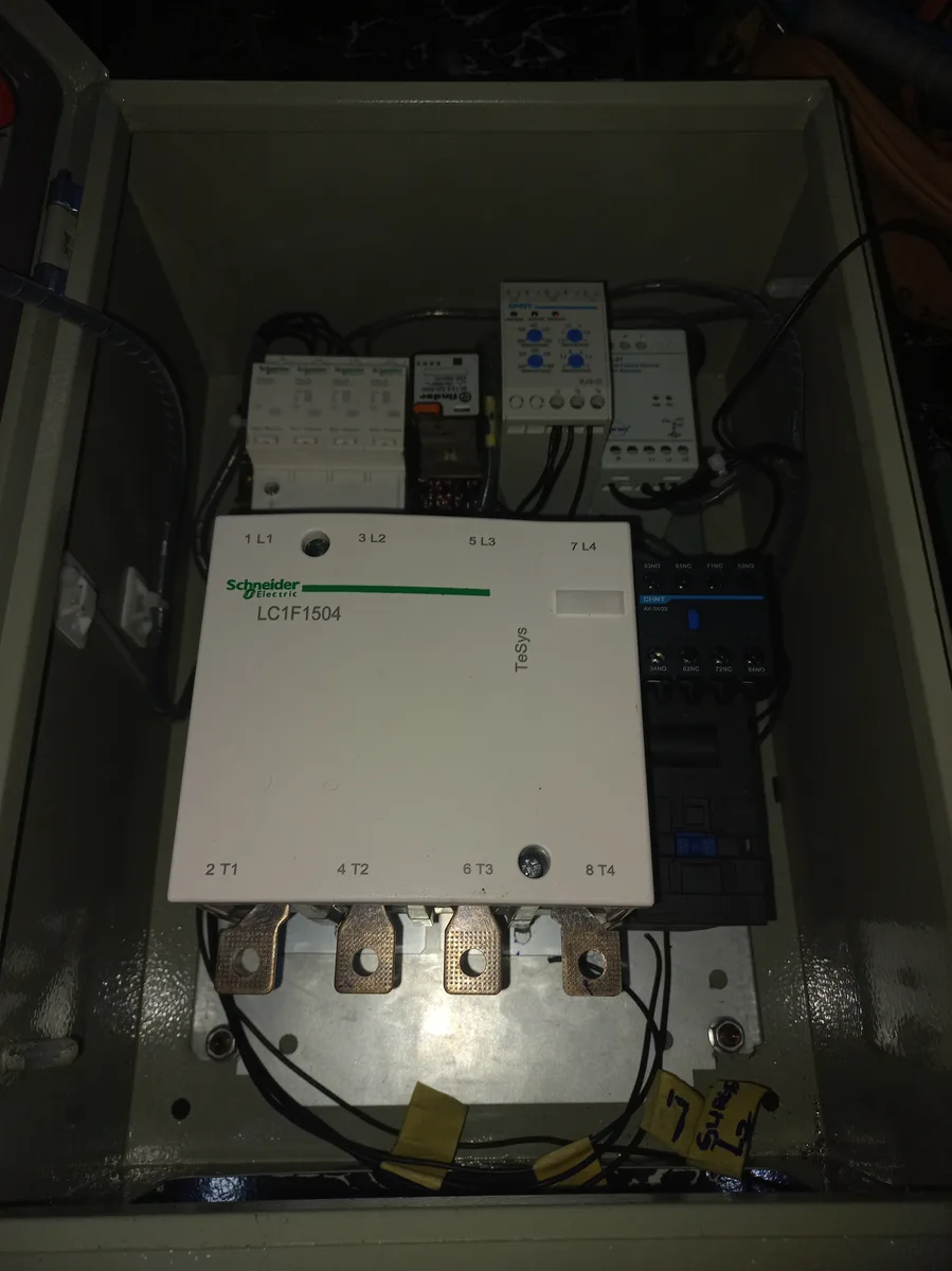
- Schneider Electric 250A 3-Phase AC Contactor — Heavy-duty electromagnetic contactor rated at 250A for main power switching. Provides reliable make/break of the 3-phase supply to the X-ray machine, controlled by the protection relay outputs.
- Finder 60.13.8.220.0040 Plug-in AC Relay — 10A / 250V~, 220V AC coil. Serves as an intermediary control relay in the protection logic chain, interfacing between the monitoring relays and the main contactor coil.
Indicators & Accessories
- LED Panel Indicator Lights — Red (fault/trip), Amber (warning/standby), Blue (phase presence), Green (system OK/power on). Mounted on the panel face for at-a-glance status monitoring.
- 35mm DIN Rail — Standard symmetrical top-hat rail for mounting all protection devices, relays, and terminal blocks.
- DIN Rail Terminal Blocks — For organised interconnection of wires between devices, ensuring clean and maintainable wiring.
- Relay Socket/Base — DIN-rail mountable socket for the Finder plug-in relay, allowing easy relay replacement without rewiring.
- Cable Trunking / Raceway — Slotted PVC trunking for organised cable routing within the enclosure.
- Ring Terminals & Cable Lugs — Crimped connectors for secure conductor terminations at all device terminals.
- Cable Ties & Spiral Cable Wrap — For cable bundling and additional organisation.
- Cable Glands — Strain-relief fittings at the enclosure entry points for incoming and outgoing cables.
- Bolts, Nuts & Mounting Hardware (M4/M6) — For securing DIN rails, terminal blocks, and components to the metal enclosure backplate.
- Metal Enclosure / Panel Box — IP-rated steel enclosure housing the complete protection assembly.
Features & Protection Scheme
The protection system implements a multi-layered defence strategy where each device handles a specific class of power anomaly. The protection devices are wired in a series-logic configuration: all monitoring relays must confirm healthy power conditions before the main contactor is allowed to engage. If any relay detects a fault, the contactor drops out immediately, disconnecting the X-ray machine from the mains.
- Layer 1 — Surge Protection (Schneider iPRU 65): First line of defence at the panel input. Clamps transient overvoltages to ≤1.9kV (Up), diverting surge current up to 65kA to earth. Each module has a visual status window — green means healthy, red means the module needs replacement.
- Layer 2 — Voltage Monitoring (CHINT XJ3-D): Continuously monitors all three phase voltages. If overvoltage exceeds the set threshold (adjustable 300–460V) or undervoltage drops below the set threshold (adjustable 300–380V), the relay opens its contact after the programmed delay, tripping the contactor.
- Layer 3 — Phase Failure Detection (ENTES MK-01): Dedicated phase failure relay providing redundant protection. Detects loss of any phase, phase asymmetry >20%, and incorrect phase sequence. Response time is near-instantaneous for phase loss events.
- Layer 4 — Control Logic (Finder Relay): The Finder plug-in relay acts as the intermediary between the monitoring relays and the contactor coil. It aggregates the fault signals and provides a clean control contact for the contactor.
- Layer 5 — Power Switching (250A Contactor): The main contactor connects or disconnects the full 3-phase supply to the X-ray machine. It only engages when all upstream protection relays confirm healthy power conditions.
- Visual Indicators: Four LED indicators provide immediate status: Green (all OK, contactor engaged), Blue (phase presence confirmed), Amber (standby/delay active), Red (fault — contactor tripped).
Design & Methodology
The project followed a structured approach from planning through to final commissioning, ensuring every connection was verified before energising the system.
Phase 1: Planning & Circuit Design
The circuit diagram was sketched on a whiteboard, mapping out the logical flow from the 3-phase mains input through each protection layer to the X-ray machine output. Component specifications were verified against the X-ray machine's power requirements (3-phase, 380–415V). The protection relay trip thresholds were pre-calculated based on the local grid voltage characteristics and the X-ray machine's acceptable operating range.
Phase 2: Component Verification & DIN Rail Assembly
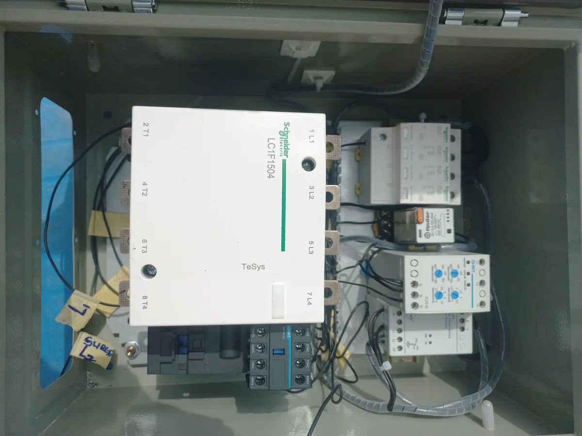
Each component was inspected and tested individually before mounting. The DIN rails were cut to size and secured to the metal enclosure backplate. Components were mounted in logical order matching the circuit diagram: surge arrester first (input side), followed by the monitoring relays, control relay, and finally the main contactor. Terminal blocks were positioned at both ends for input and output connections.
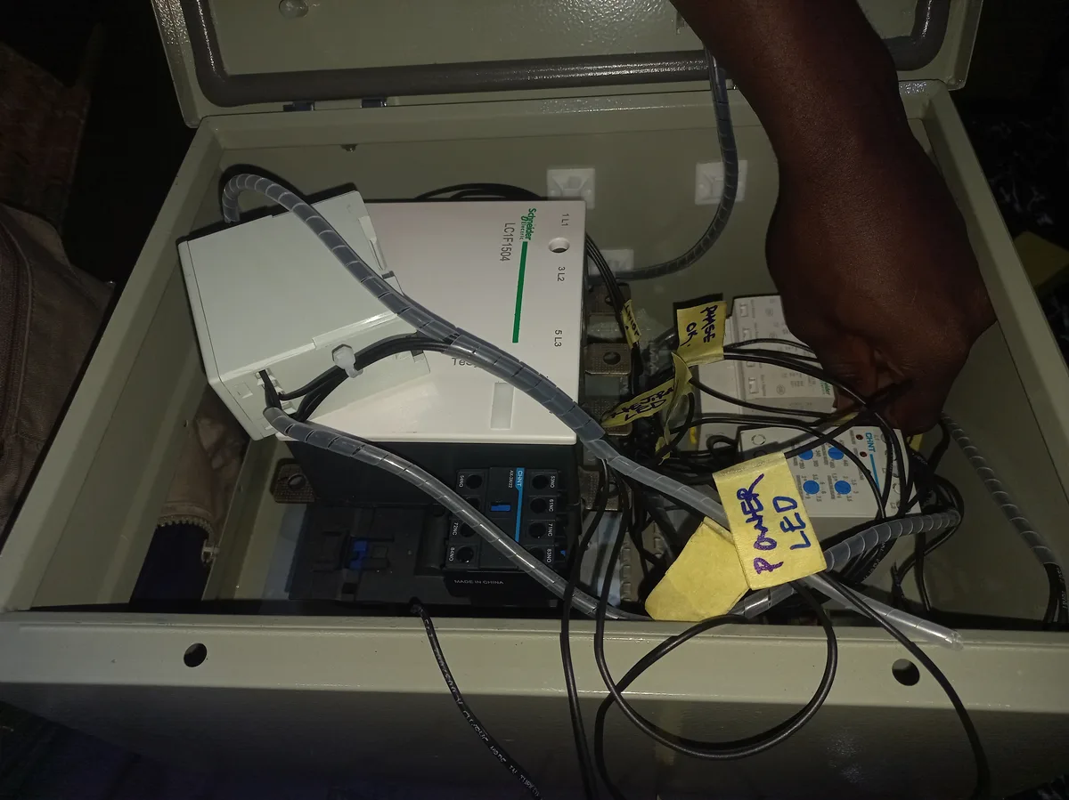
Phase 3: Wiring & Interconnection
Wiring was carried out phase-by-phase (L1, L2, L3, then N/PE) to avoid cross-connections. All conductor terminations used crimped ring terminals or cable lugs for reliable contact. The control circuit was wired separately from the power circuit to minimise electromagnetic interference. Cable trunking was used throughout to maintain organised routing, and each conductor was labelled at both ends for future maintenance traceability.
Challenges & Solutions
- Enclosure Space Constraints: Fitting a 250A contactor alongside multiple DIN-rail devices required careful spatial planning. The solution was to mount the contactor on a separate section of the backplate and run the control wiring through trunking to keep the layout clean.
- Relay Interlock Logic: Ensuring the CHINT XJ3-D and ENTES MK-01 operated in proper coordination without nuisance tripping required setting appropriate delay values. The CHINT's adjustable delays were tuned to tolerate brief grid transients while still responding quickly to genuine faults.
- Heat Dissipation: The 250A contactor generates heat under load. Adequate clearance was maintained around the contactor, and ventilation holes in the enclosure lid were considered to prevent thermal buildup.
- Phase Identification: Correct phase labelling (L1/L2/L3 = R/Y/B) was critical. Each phase was colour-coded and verified with a phase sequence meter before connecting to the protection relays to ensure the XJ3-D and MK-01 would detect phase rotation correctly.
Results & Testing
After assembly, the panel underwent a systematic testing procedure to verify all protection functions before connecting to the X-ray machine.
- Phase Failure Test: Disconnecting each phase individually confirmed that both the CHINT XJ3-D and ENTES MK-01 detected the loss and tripped the contactor within the set delay period.
- Overvoltage/Undervoltage Test: The CHINT XJ3-D thresholds were adjusted and verified using a variable voltage source, confirming trip at the set upper and lower limits.
- Surge Arrester Verification: The Schneider iPRU 65 modules were visually inspected — all four status windows showed green (healthy), confirming the varistors were intact.
- Contactor Operation: The 250A contactor was confirmed to engage smoothly when all protection relays showed healthy status, and to drop out immediately when a fault was simulated.
- Indicator Lights: All four LED indicators (Red, Amber, Blue, Green) were verified to display correct states during normal operation, standby, and fault conditions.
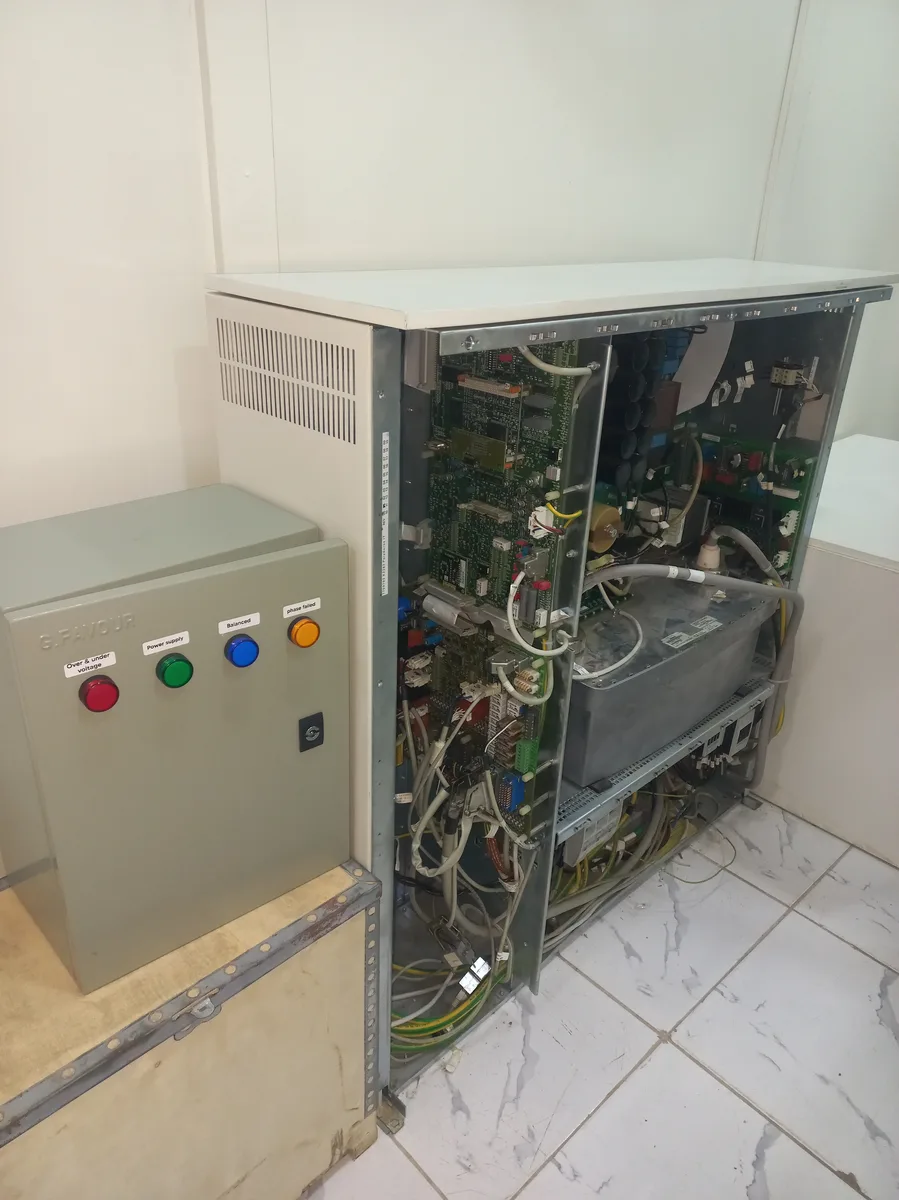
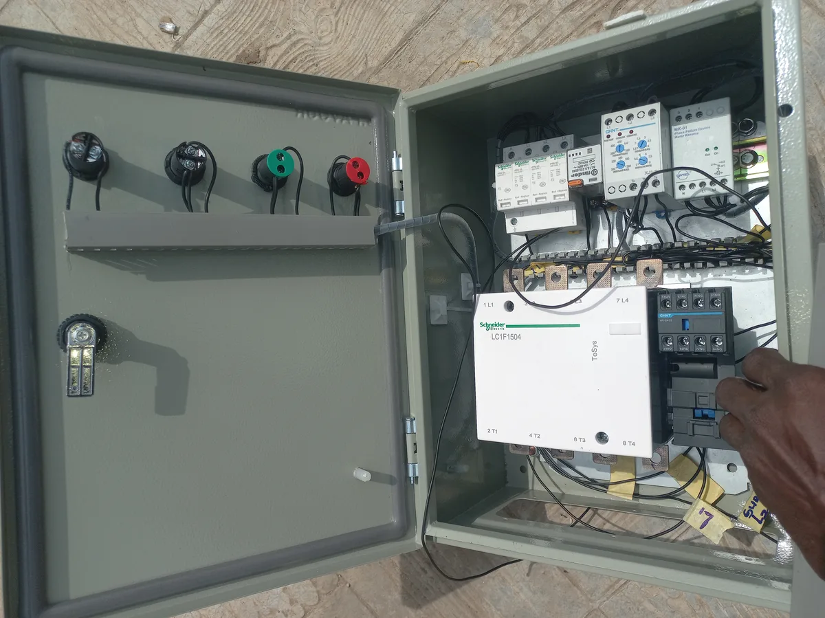
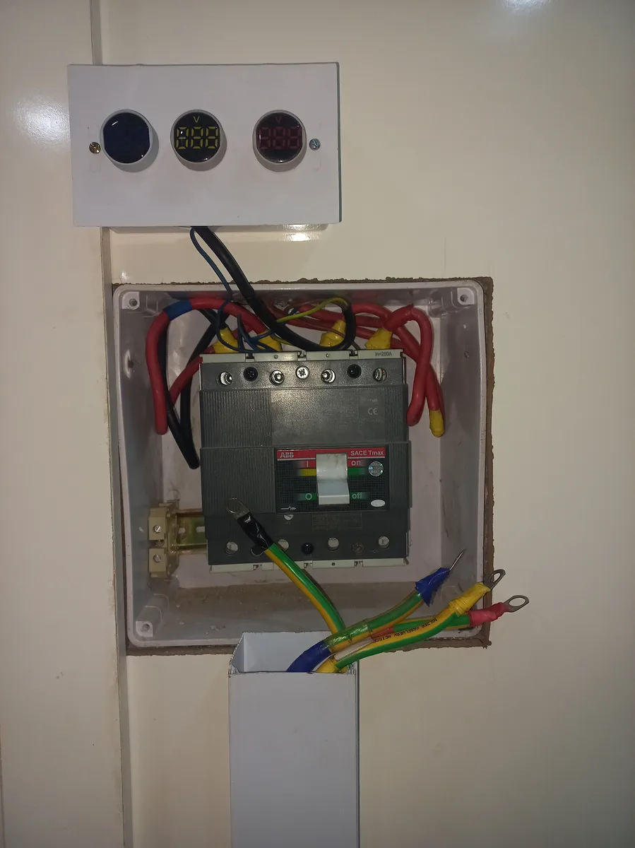
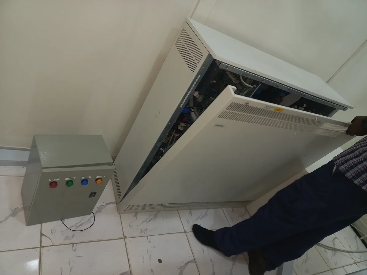
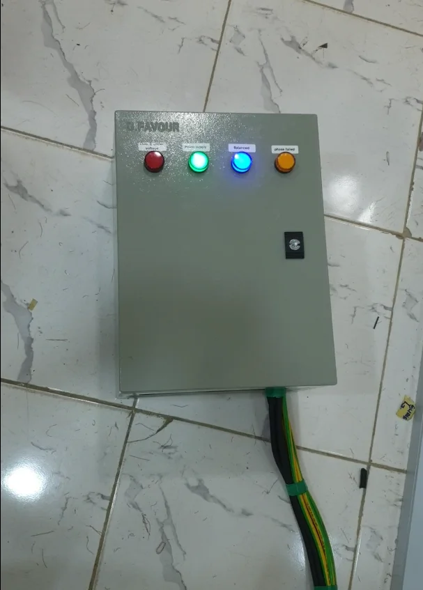
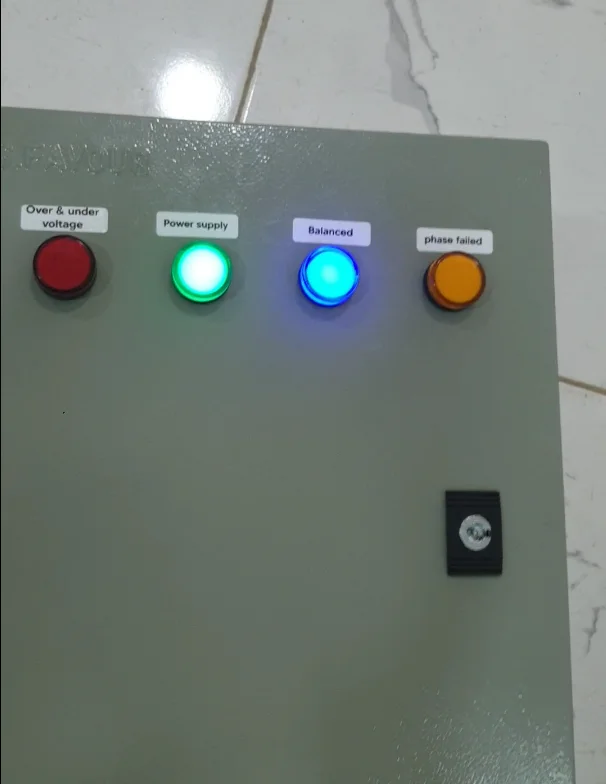
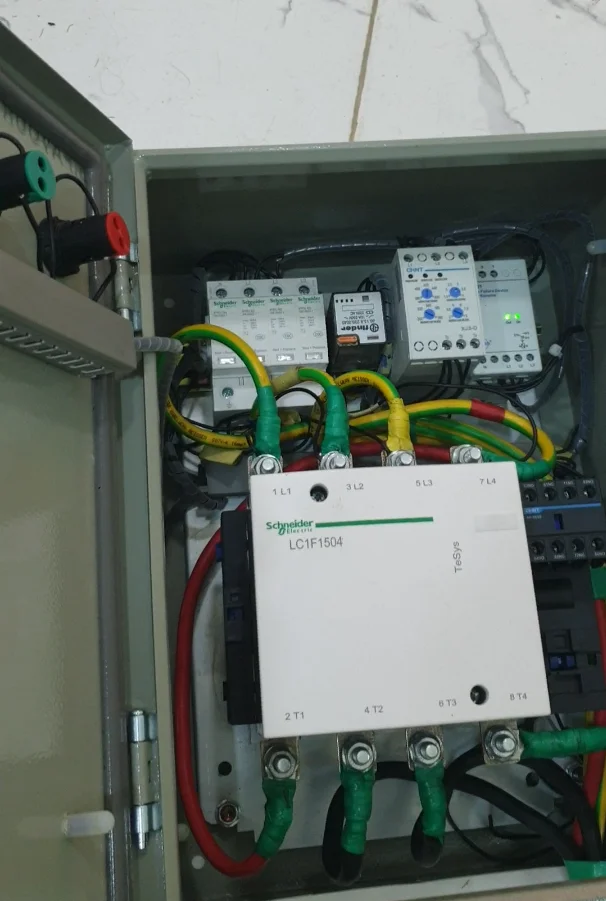
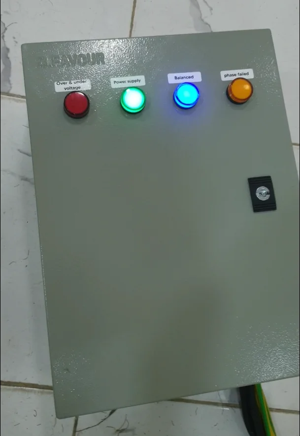
Powered-On Results
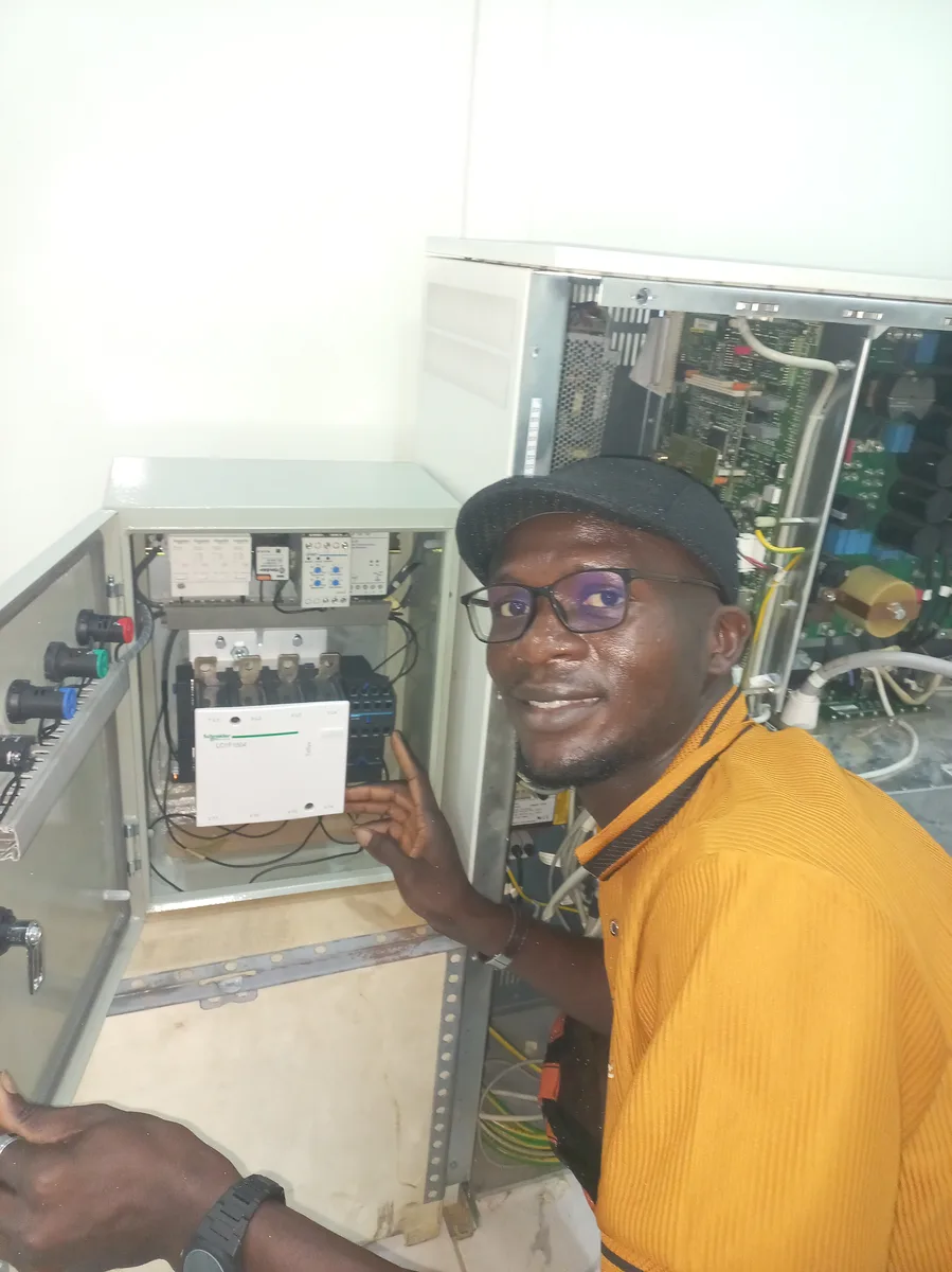
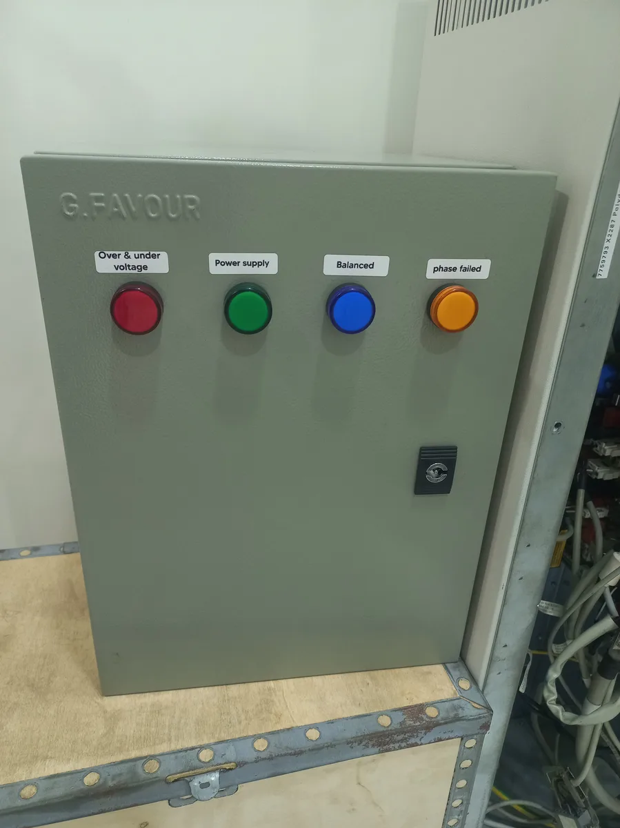
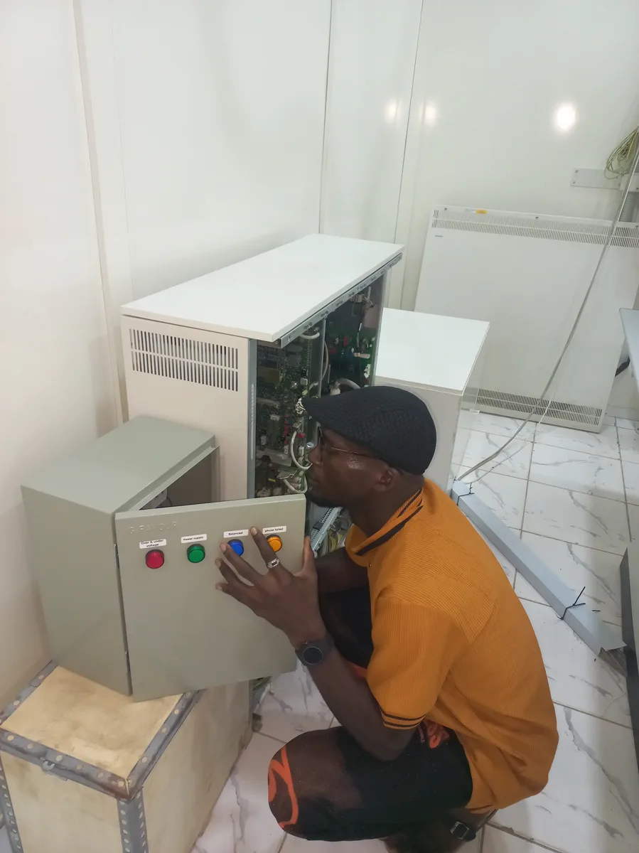
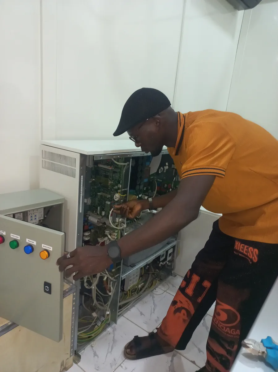
The following images show the protection panel powered on and operating under normal 3-phase supply conditions. All four LED indicators confirm correct system status: the Red indicator (Over & Under Voltage) remains off — confirming voltage is within the safe threshold; the Green indicator (Power Supply) is lit — confirming live 3-phase mains; the Blue indicator (Balanced) is lit — confirming all three phases are present and balanced; and the Amber indicator (Phase Failed) remains off — confirming no phase loss detected. The interior view shows the Schneider Electric LC1F1504 TeSys contactor engaged, with the Finder relay, iPRU 65 surge arrester, and CHINT XJ3-D monitoring relay all operational.
Future Enhancements
- Digital Power Meter Integration: Adding a PZEM-004T or equivalent 3-phase energy meter to log voltage, current, and power data from the X-ray machine supply for performance tracking and fault diagnostics.
- IoT Remote Monitoring: Integrating an ESP32 module to push real-time power status and fault alerts to a cloud dashboard or Telegram bot, enabling remote oversight of the X-ray machine's power supply health.
- Automatic Reconnection with Timer: Implementing a programmable re-close timer that automatically re-engages the contactor after a configurable delay once the fault condition clears, reducing manual intervention.
- Thermal Monitoring: Adding PTC thermistors on the contactor and cable entry points to detect abnormal heating and trigger a pre-emptive shutdown before thermal damage occurs.
Demonstration & Resources
This video provides a detailed walkthrough of the protection panel build, from component selection and assembly through to the final live testing. You can watch the embedded video below or click the link to view it on YouTube.
- YouTube Video: Watch the Full Build on YouTube
Project Gallery
A comprehensive visual record of the project from planning through to the completed protection panel. Click any image to view it in full resolution.
Planning & Components
Component Close-ups
Assembly & Wiring
Completed System
Powered-On Results
Closing Remarks
I sincerely appreciate you taking the time to explore my portfolio and learn about my work and expertise. It is my hope that these projects and insights have demonstrated my passion for innovation, my technical skills, and my dedication to delivering impactful solutions.
If you have any questions, require further information, or wish to discuss potential collaborations, I would be delighted to connect. Please feel free to reach out via the Contact section. Your feedback and inquiries are highly valued and will be addressed promptly.
Thank you once again for your interest in my work. I look forward to the opportunity to collaborate and contribute meaningfully to your projects or organization. Together, let us innovate and achieve excellence.
Best regards,
Damilare Lekan, Adekeye.