Dual-Trigger Emergency with ESP32, DFRobot PPG Sensor, NEO-6M GPS, SIM800L GSM, Firebase RTDB, and NTP Time Sync
This project is a hybrid online/offline IoT personal safety device designed for women at risk. It integrates biometric monitoring, real-time GPS tracking, GSM emergency SMS alerting, and Firebase cloud telemetry into a single self-contained portable enclosure powered by a LiPo battery with USB-C charging.
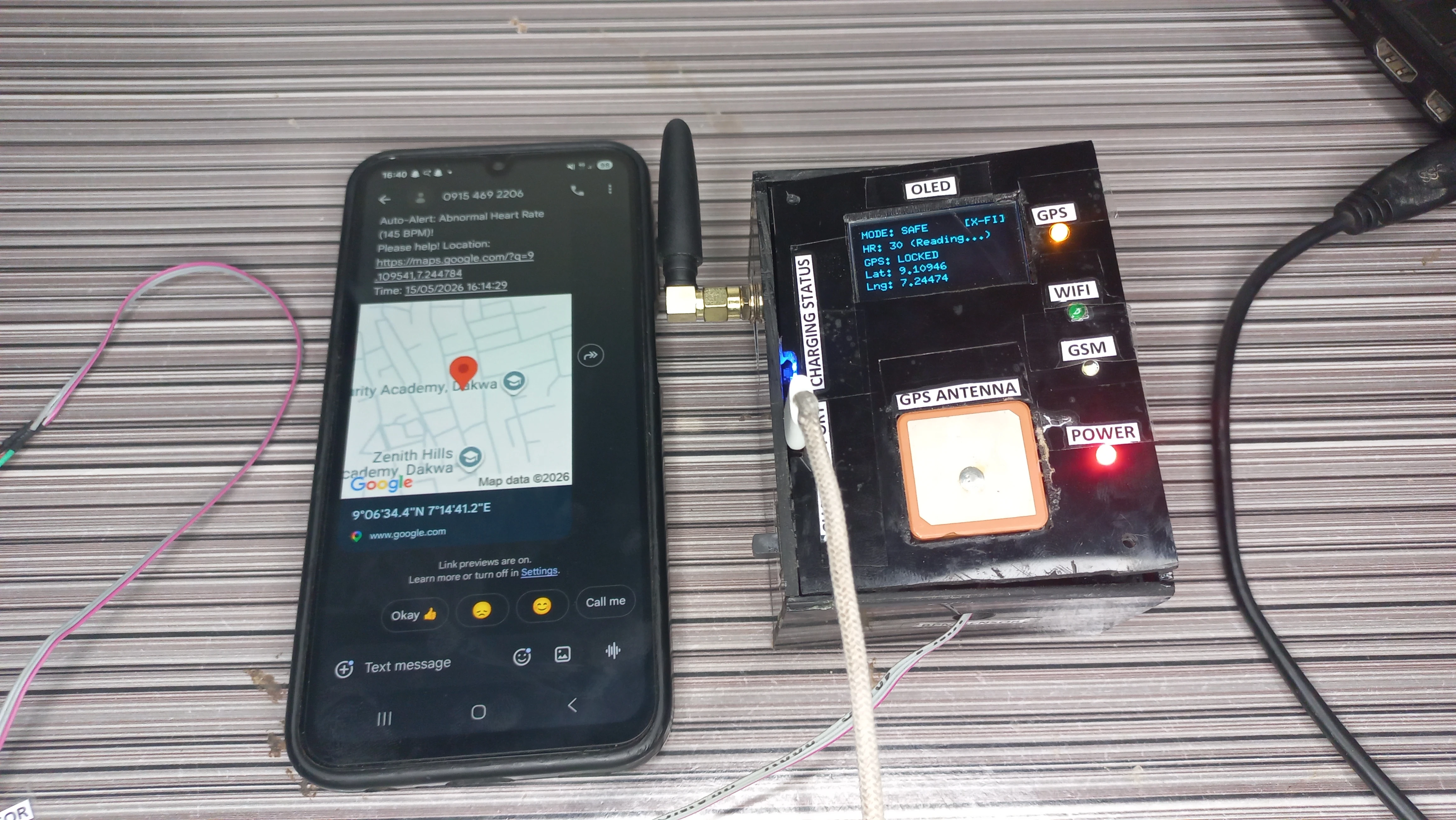
The device features a dual-trigger emergency system. The user can manually press a physical panic button for an immediate alert, or the system automatically detects a biometric anomaly when the heart rate falls below 50 BPM or rises above 120 BPM. To prevent false alarms, five consecutive abnormal readings are required before the automatic alert fires. On triggering, the device acquires GPS coordinates, constructs a Google Maps URL, stamps the event with an NTP-sourced Nigeria UTC+1 timestamp, and dispatches an SMS via SIM800L. All events are simultaneously synced to Firebase Realtime Database for remote monitoring.
A 2-second long press on the same panic button resets the system to safe mode, sends a confirmation SMS, and extinguishes the buzzer. The device operates fully offline if Wi-Fi is unavailable: GSM SMS continues to function without any cloud connectivity. A non-blocking millis()-based architecture keeps GPS parsing, heart-rate sampling, button debounce, buzzer control, Firebase sync, and OLED display all running concurrently without any blocking delay() calls in the main loop.
pool.ntp.org and formatted DD/MM/YYYY HH:MM:SSmillis() timers; zero blocking loops in loop()The device is organised into six concurrent subsystems all driven by a single non-blocking loop():
| Component | Model / Spec | Role |
|---|---|---|
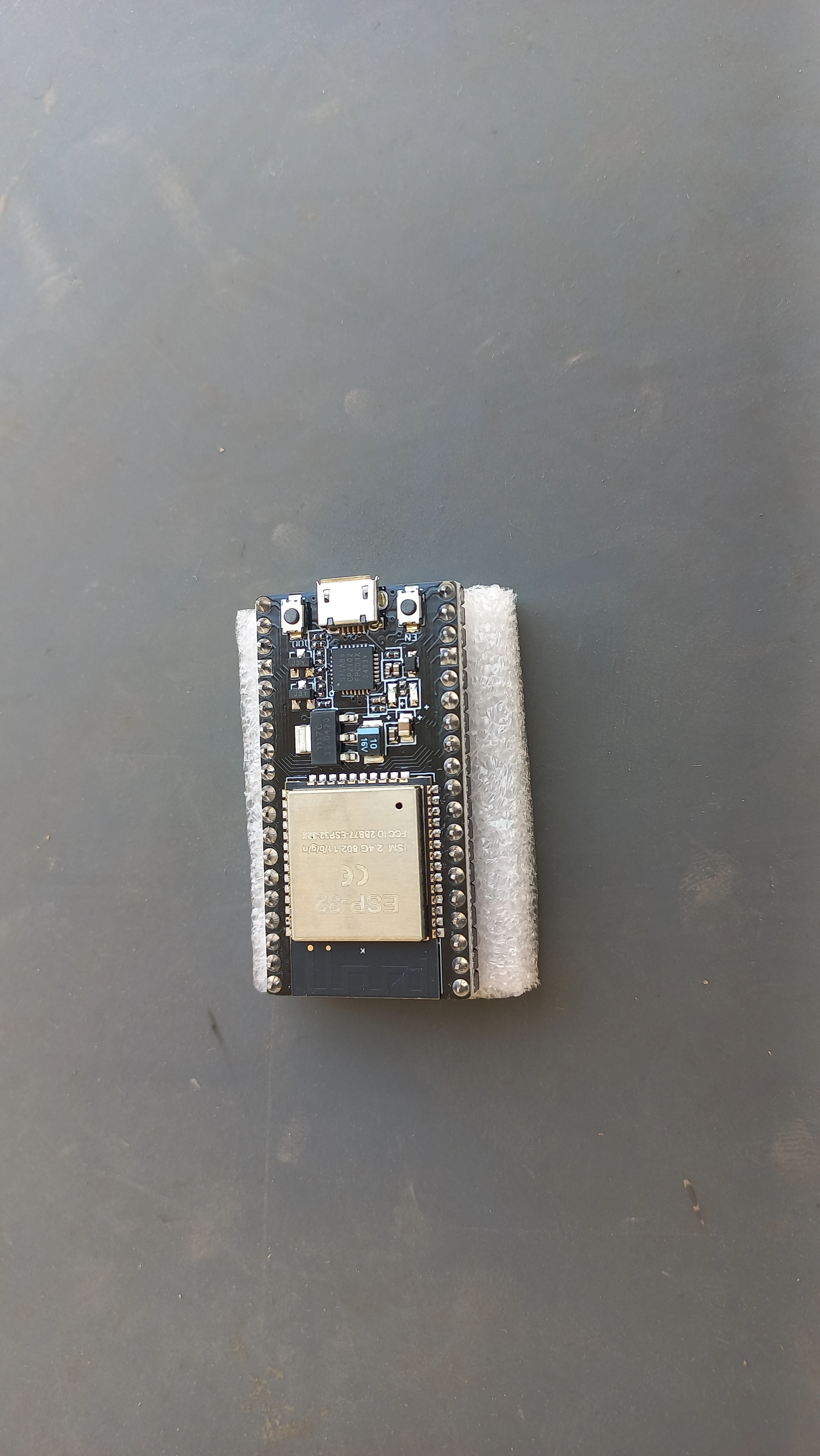
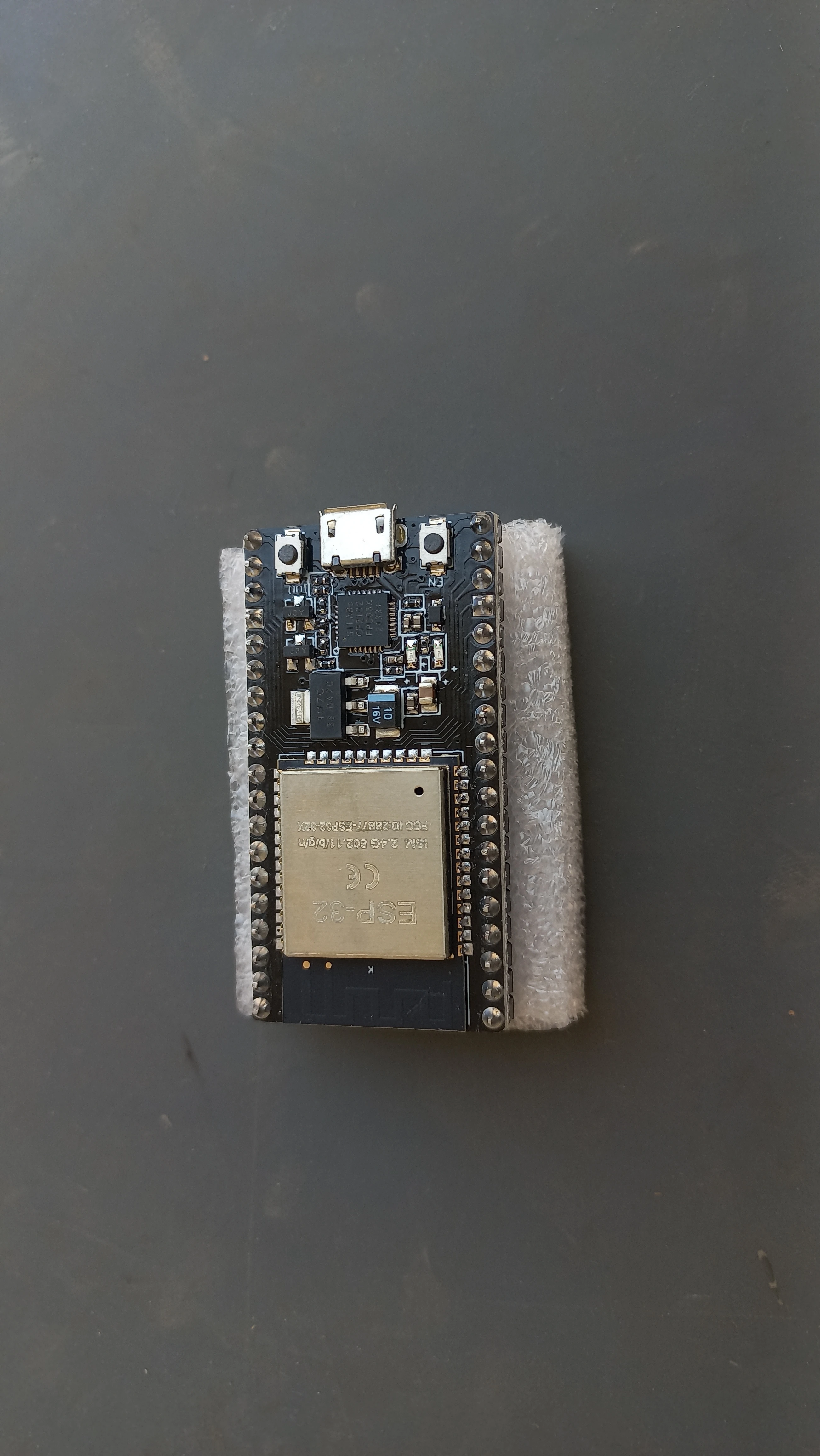
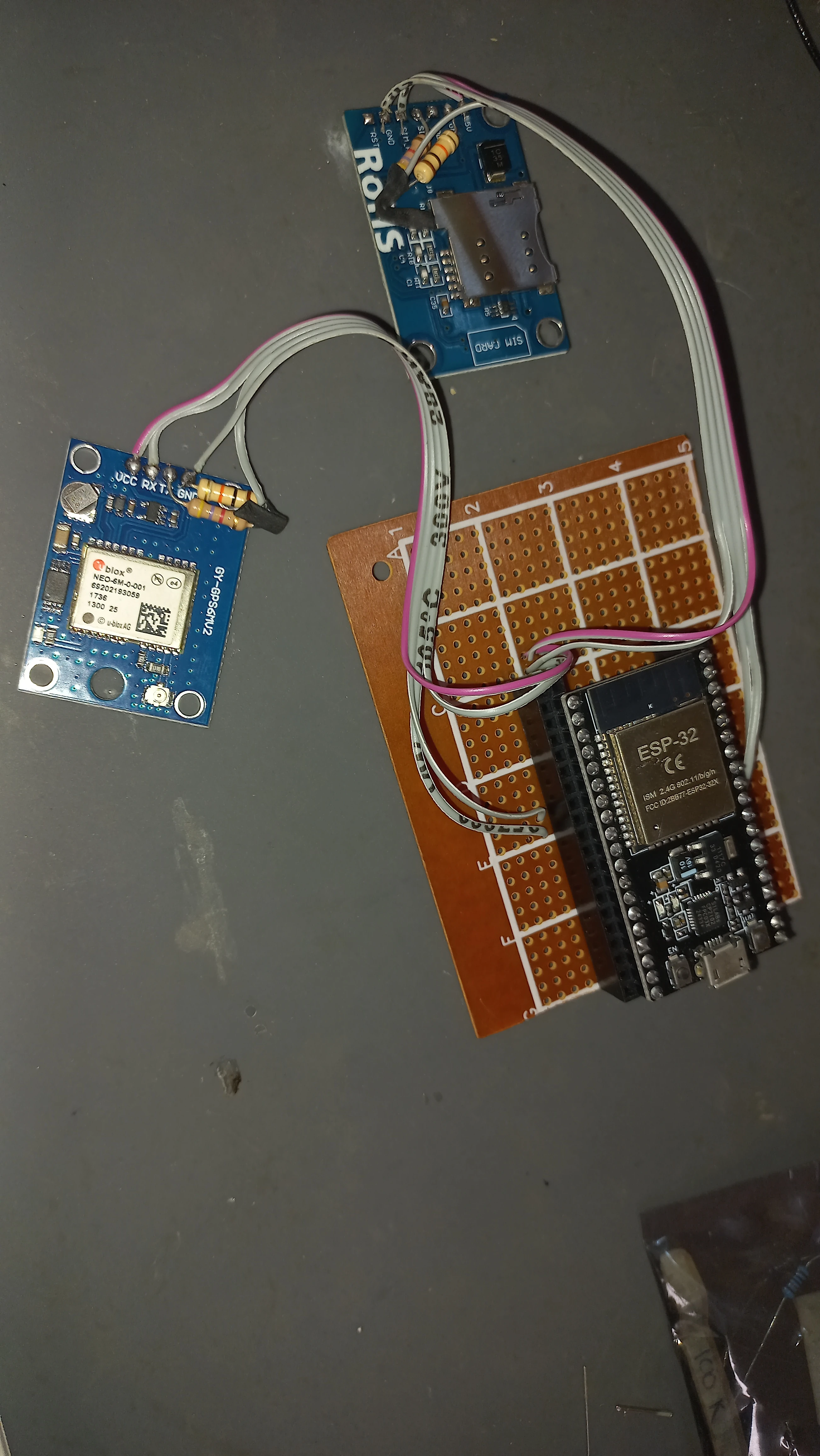
| Microcontroller | ESP32 Dev Board (30-pin) | Central processing, Wi-Fi, UART, I2C, ADC |
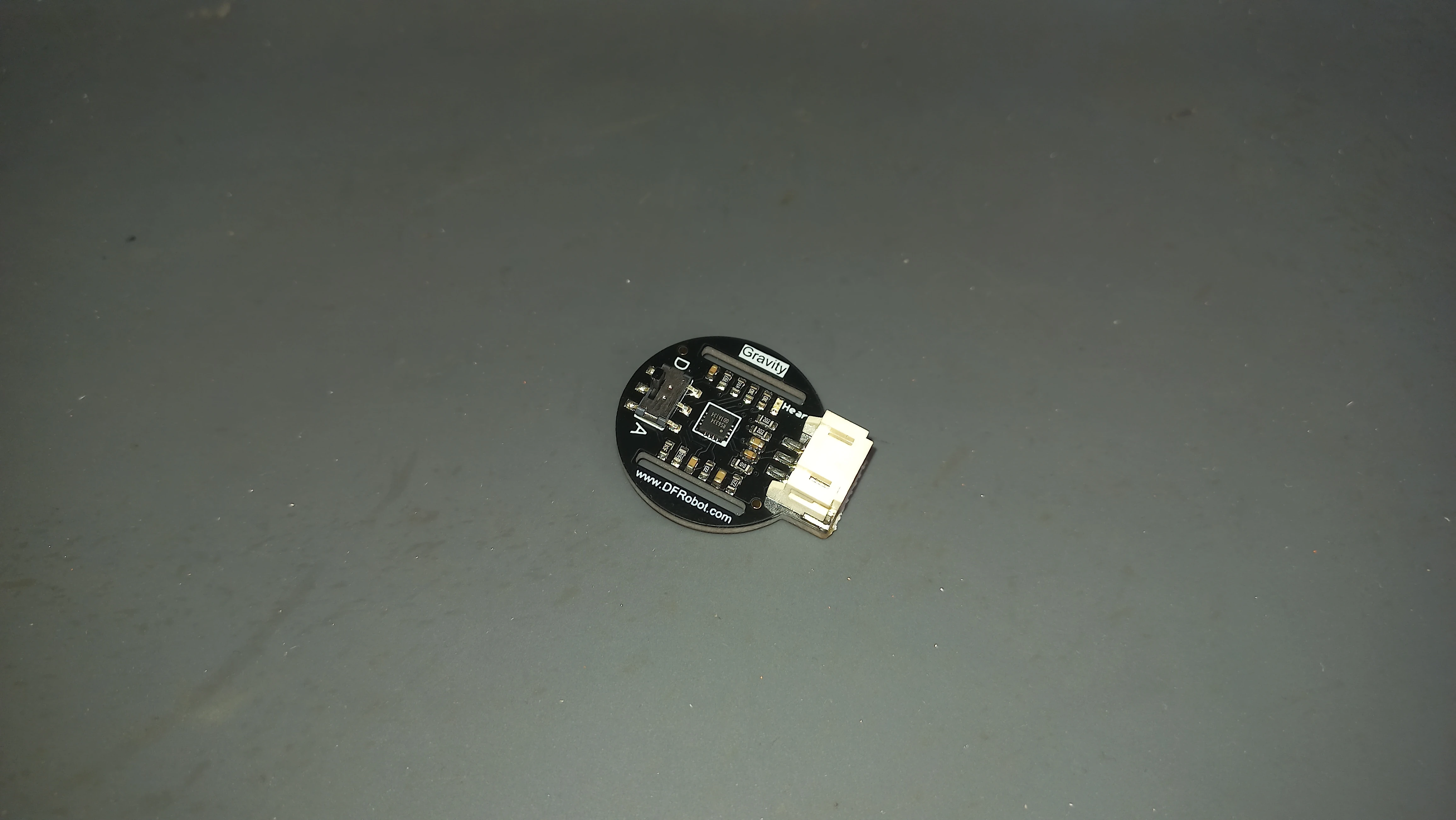
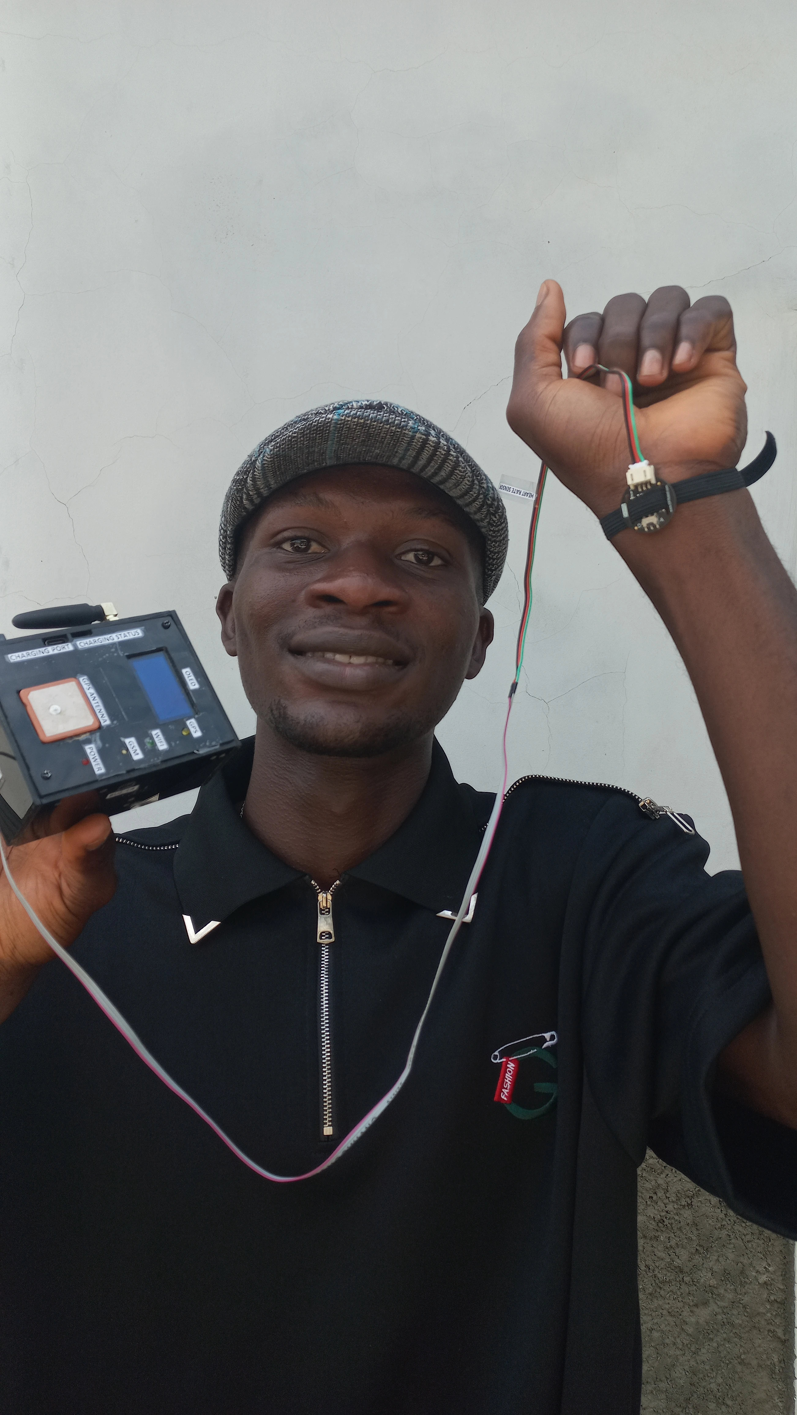
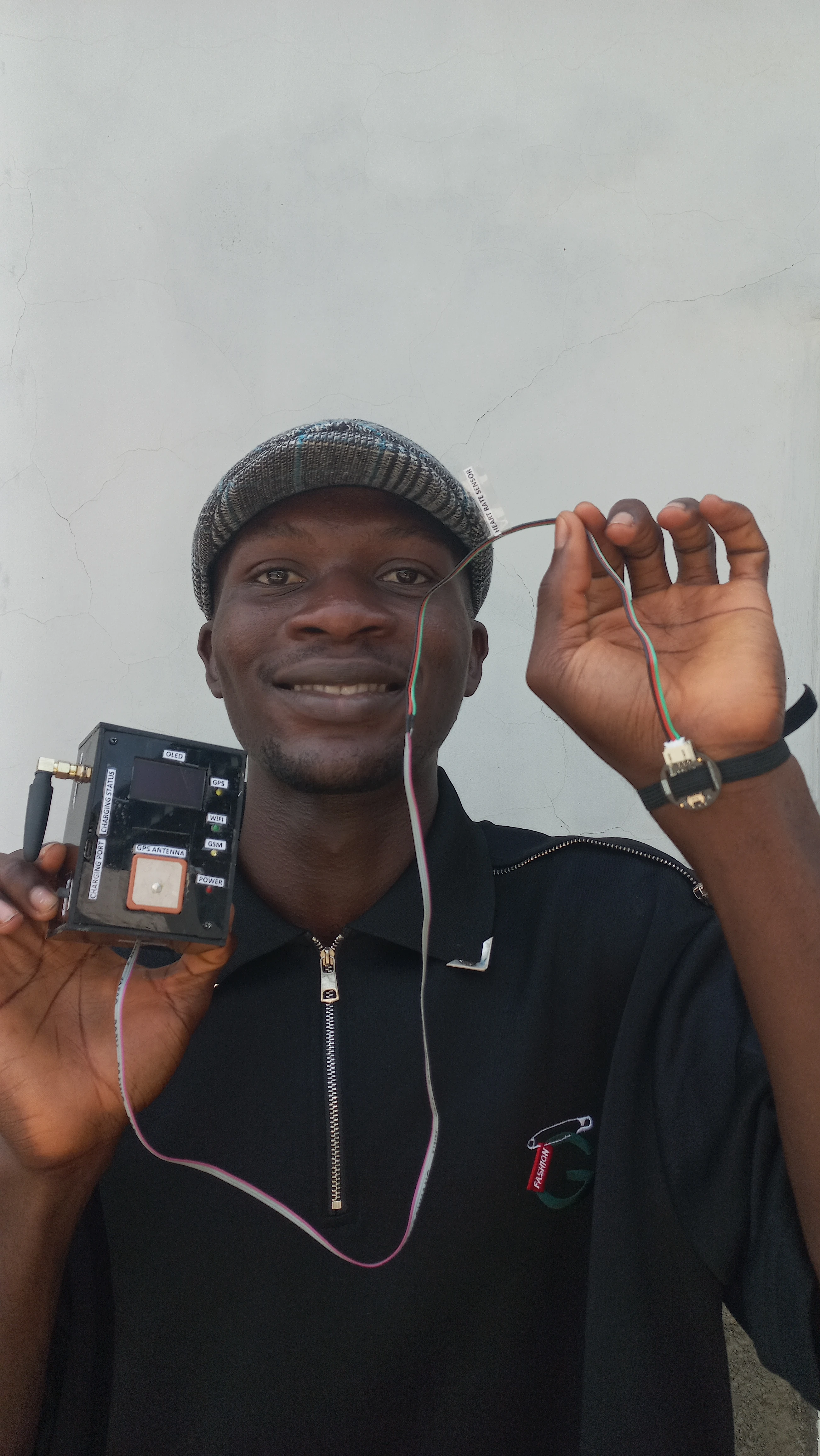
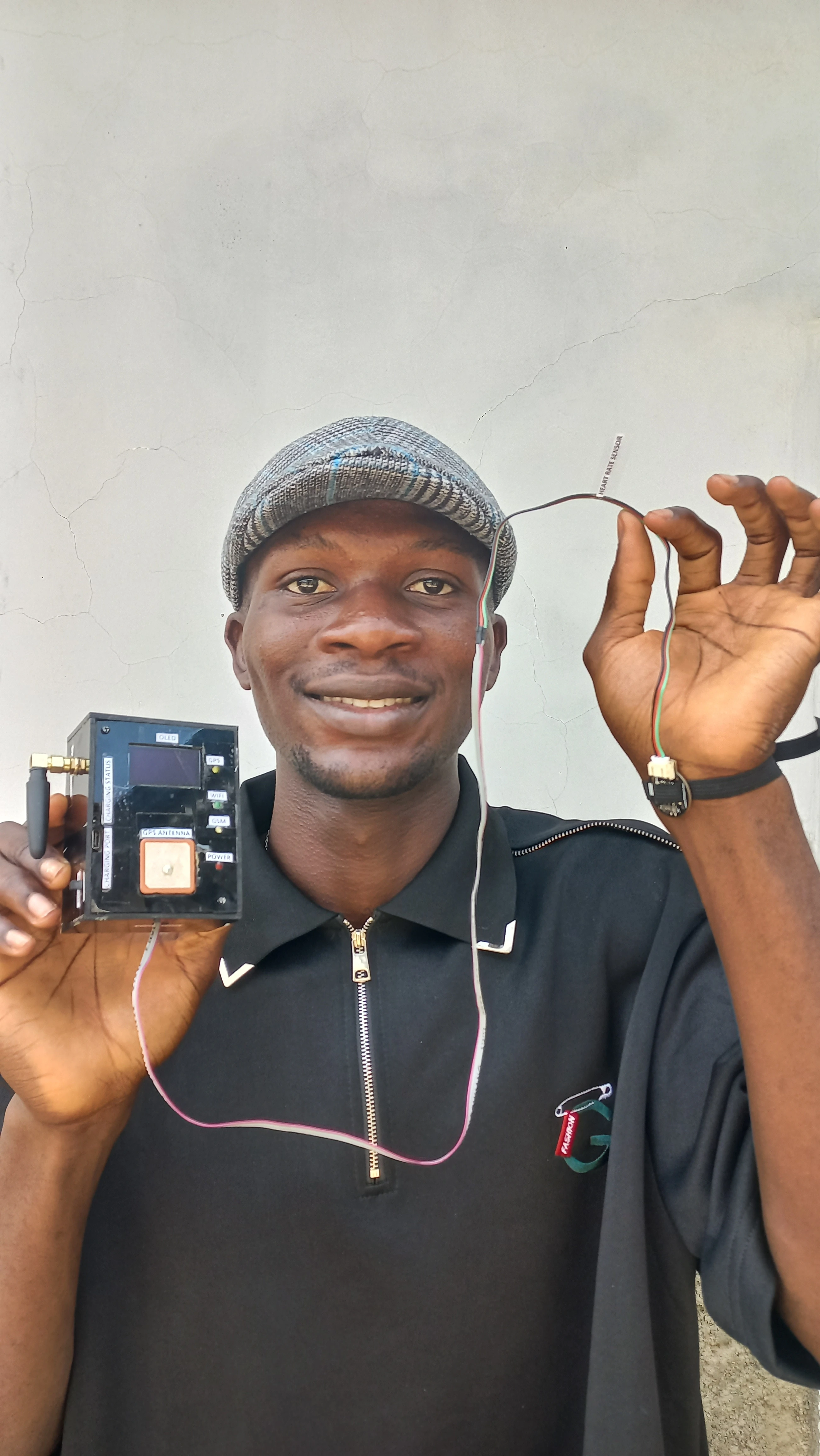
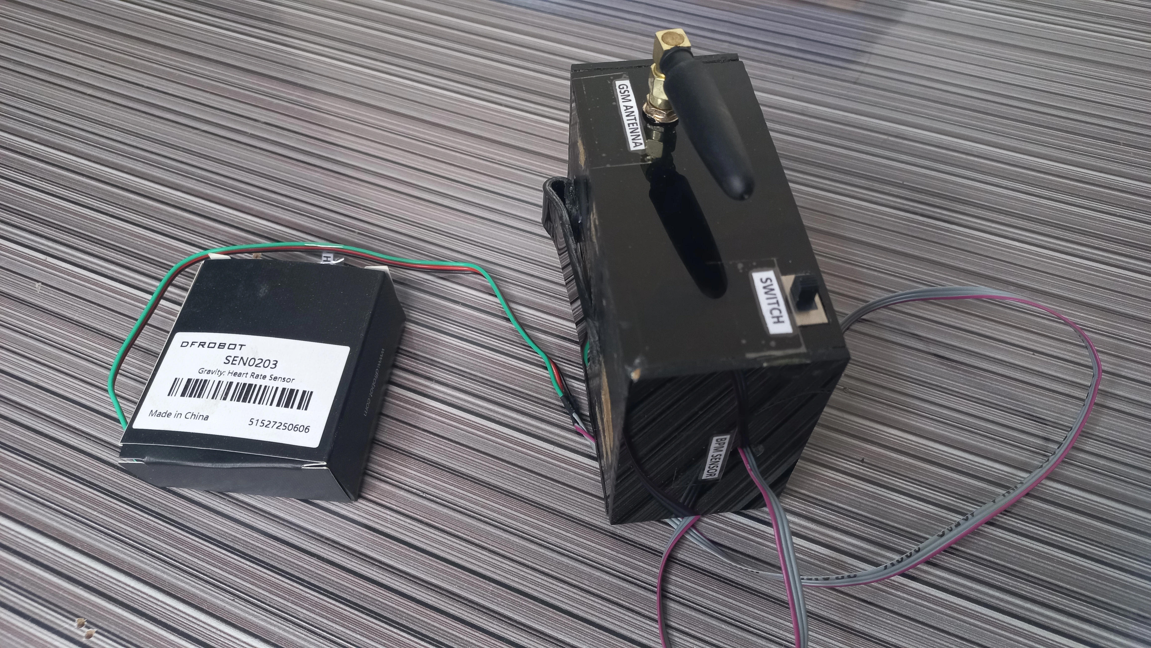
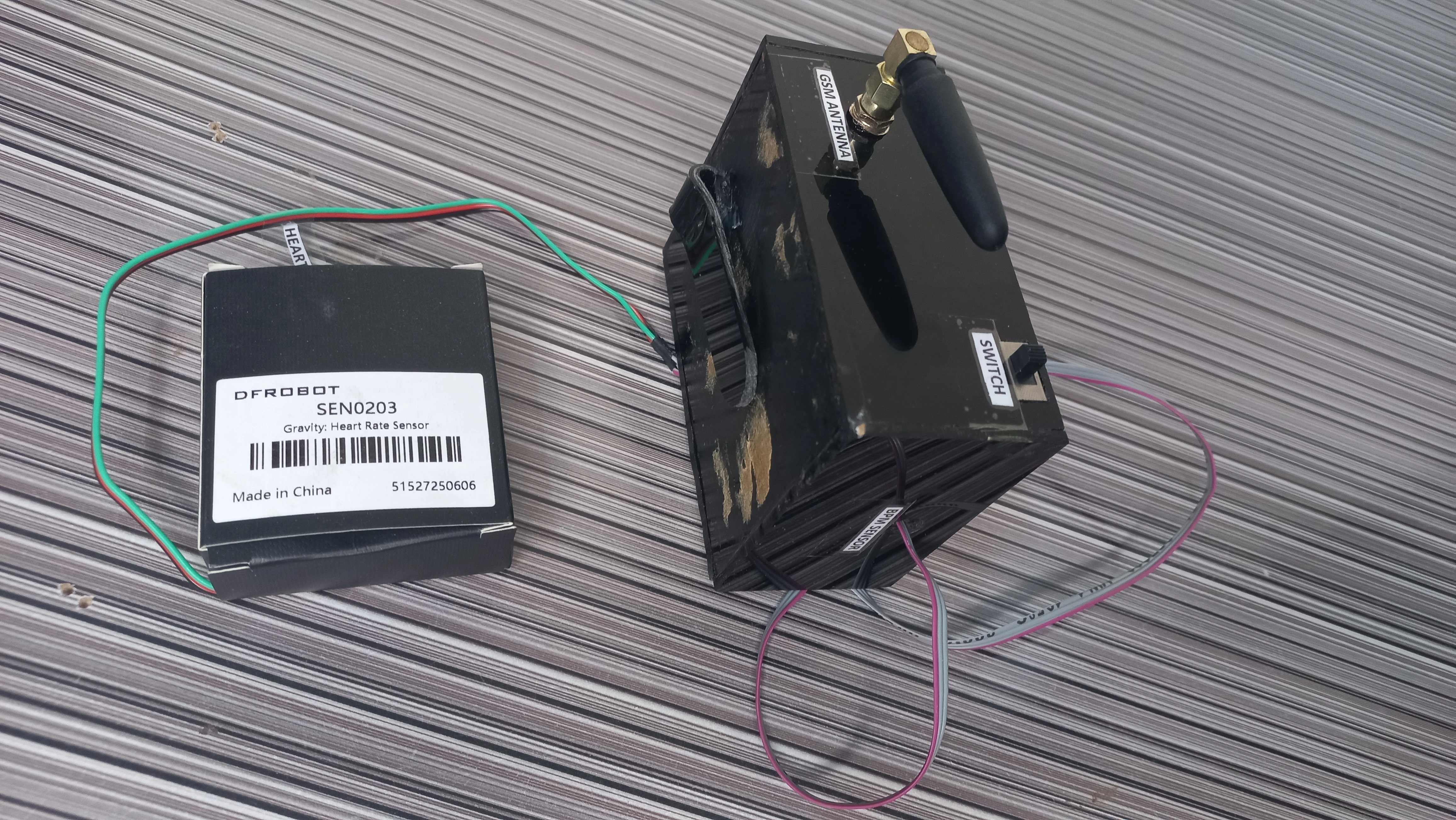
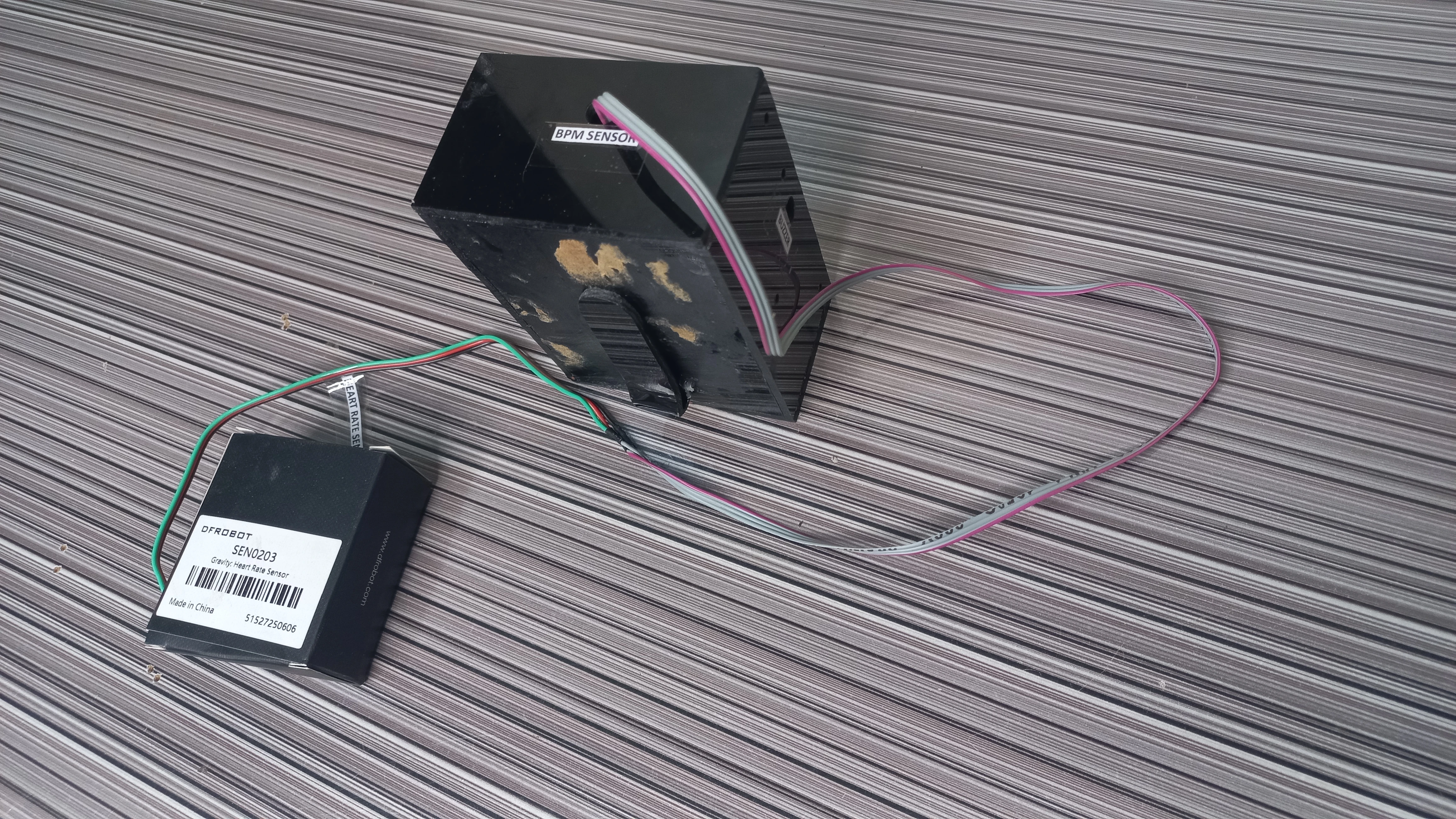
| Heart Rate Sensor | DFRobot Gravity PPG SEN0203 (analog) | Photoplethysmography, finger-clip optical PPG, ADC GPIO 36 |
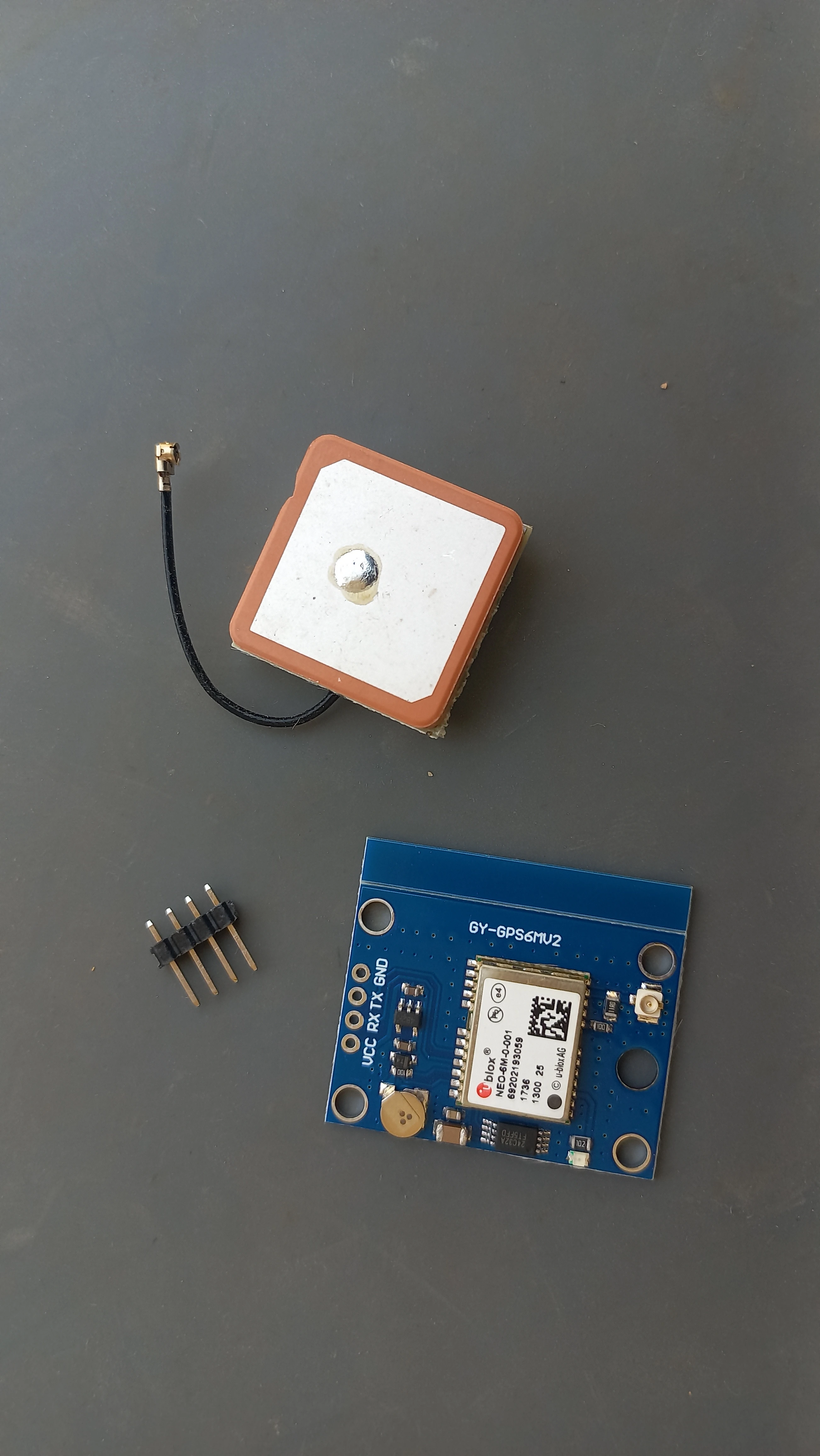
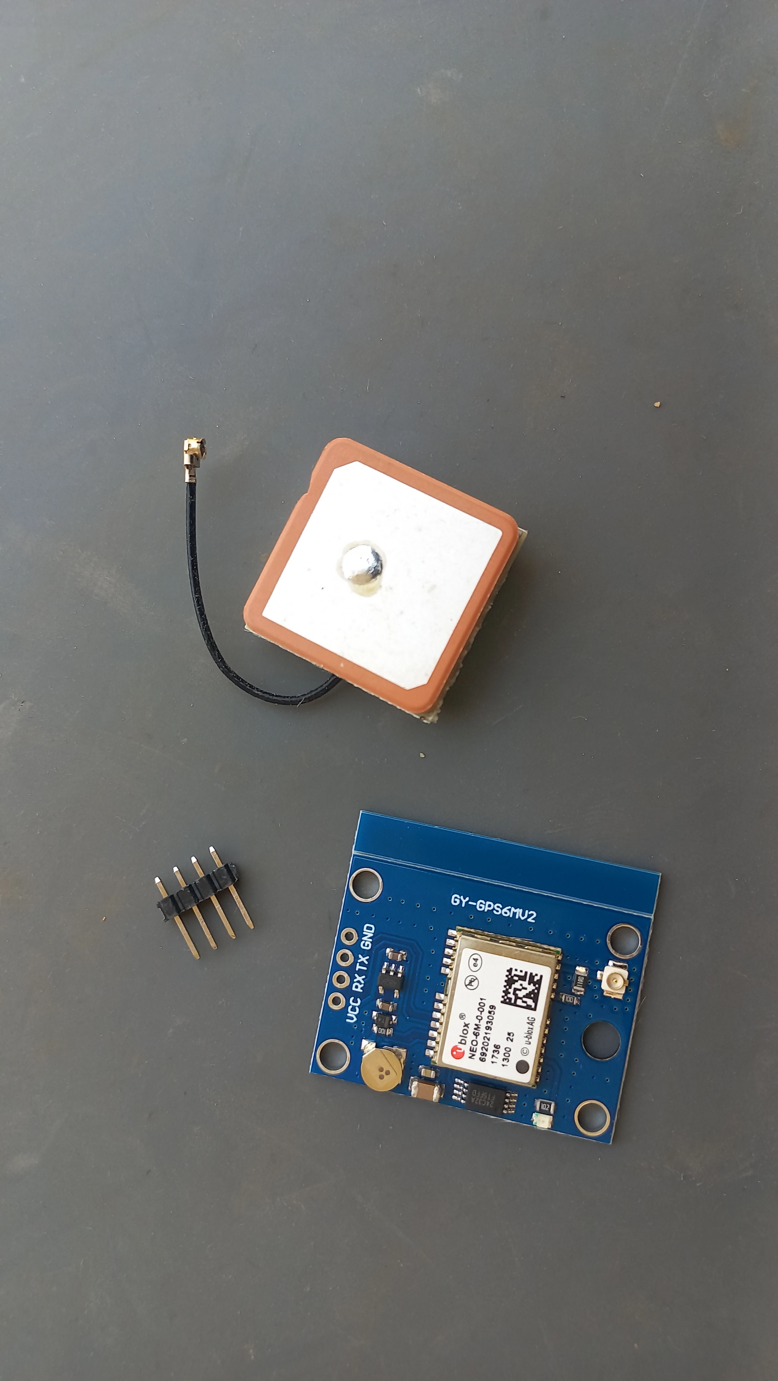
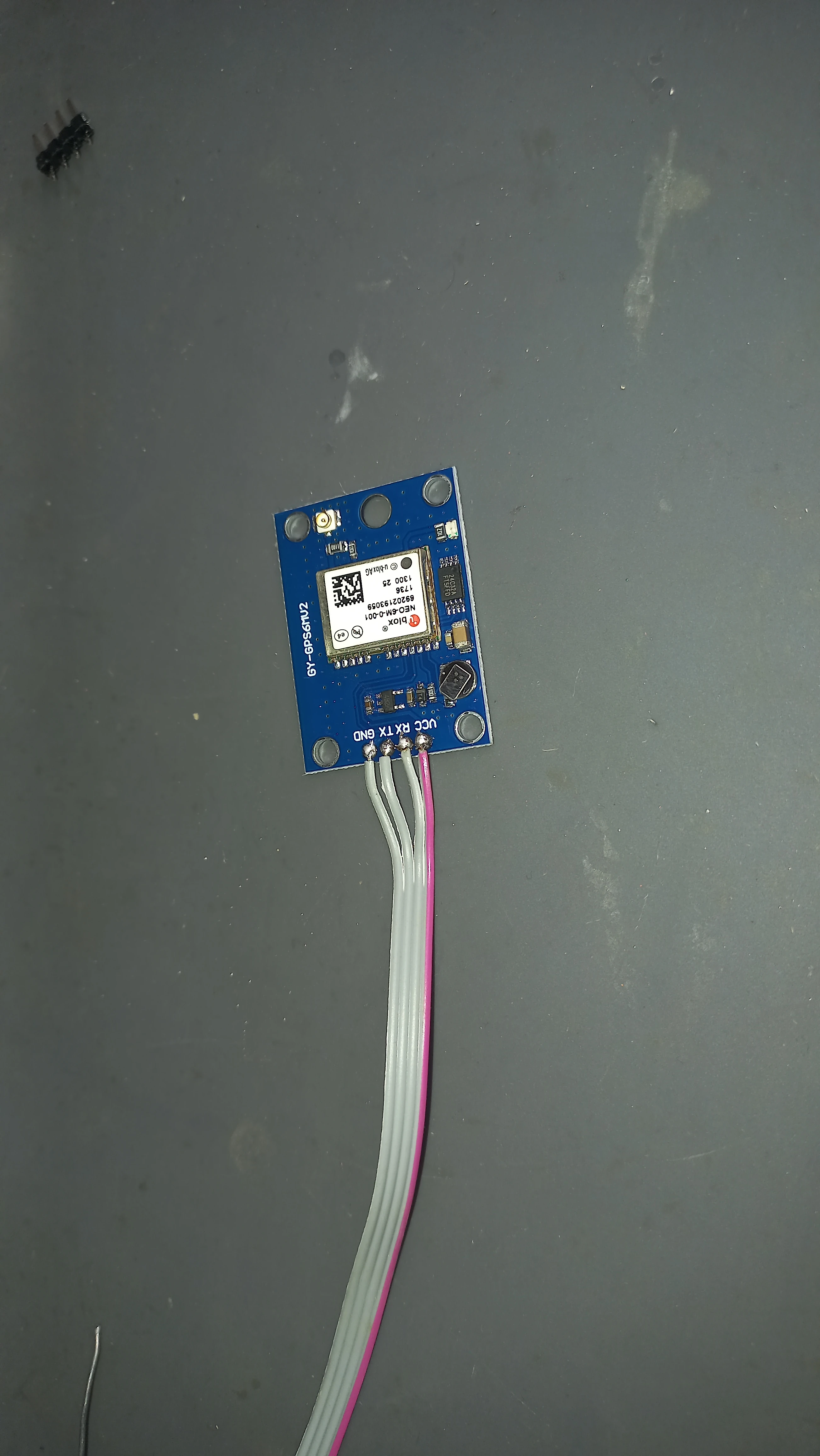
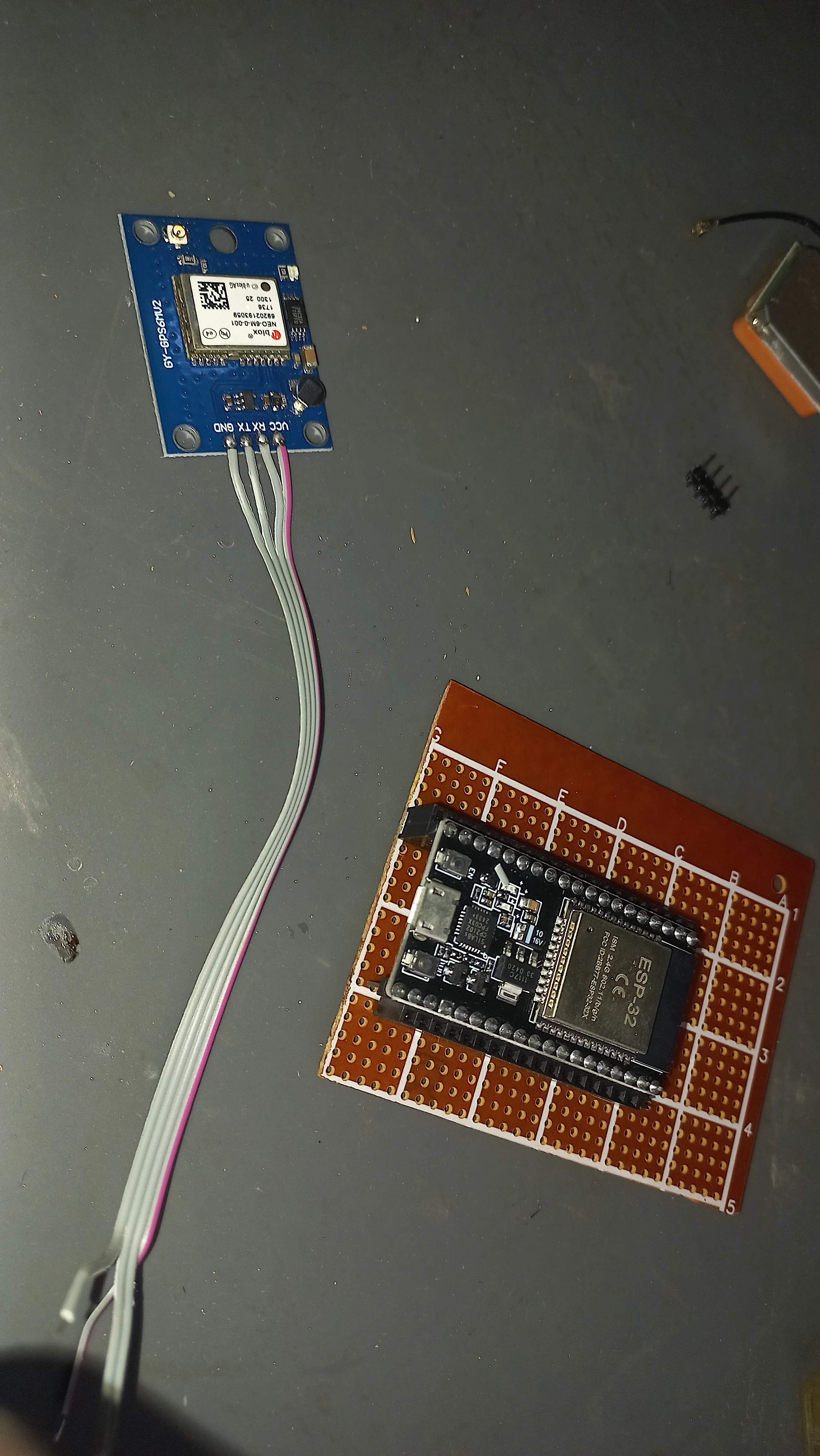
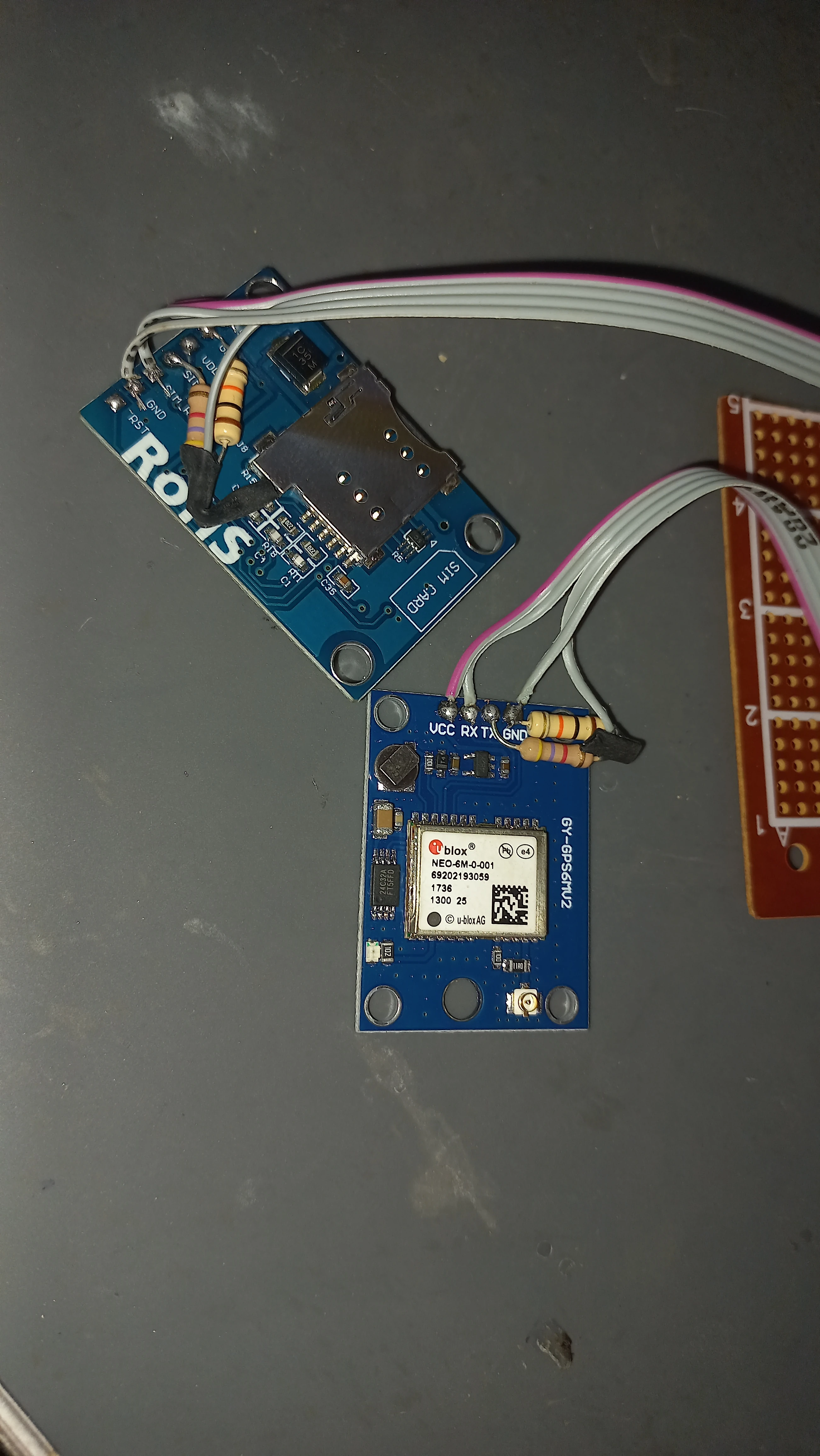
| GPS Module | NEO-6M GY-GPS6MV2 with ceramic patch antenna | Real-time location acquisition over UART2 |
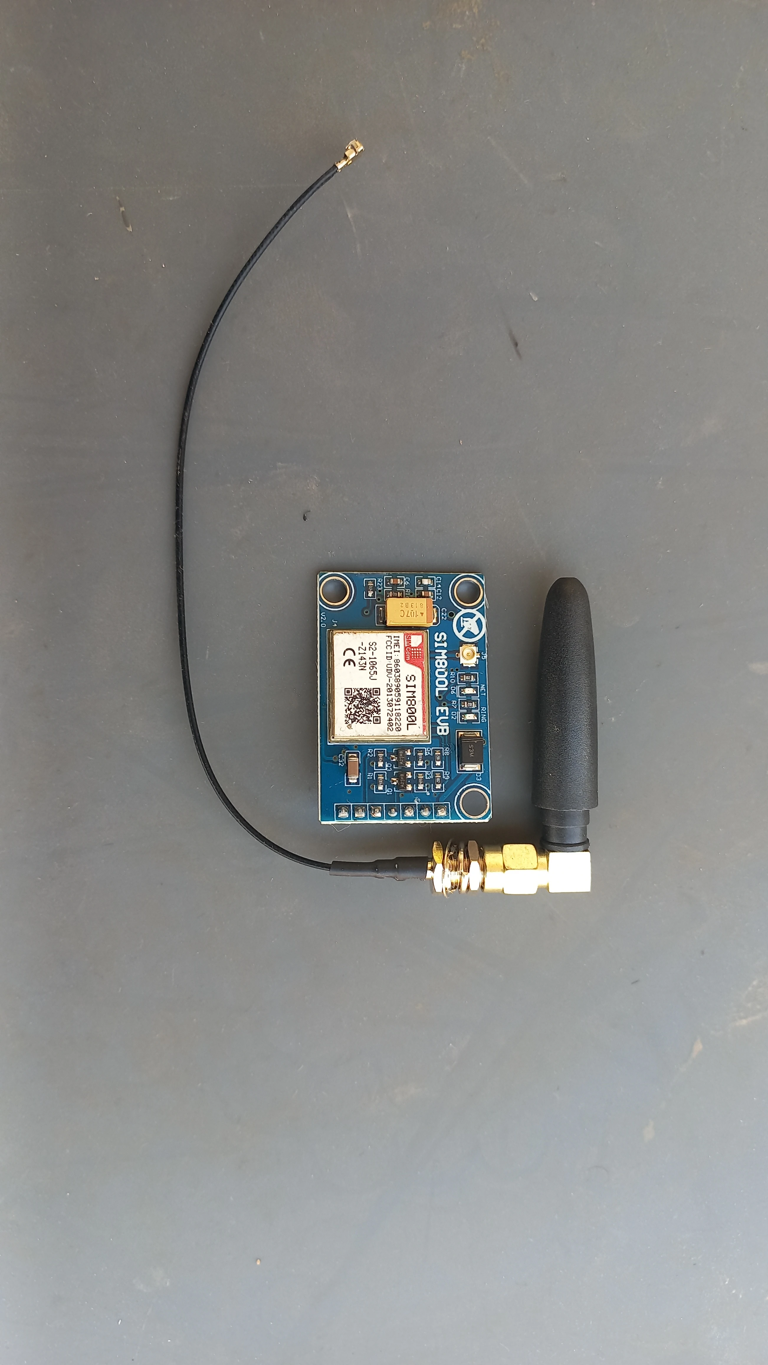
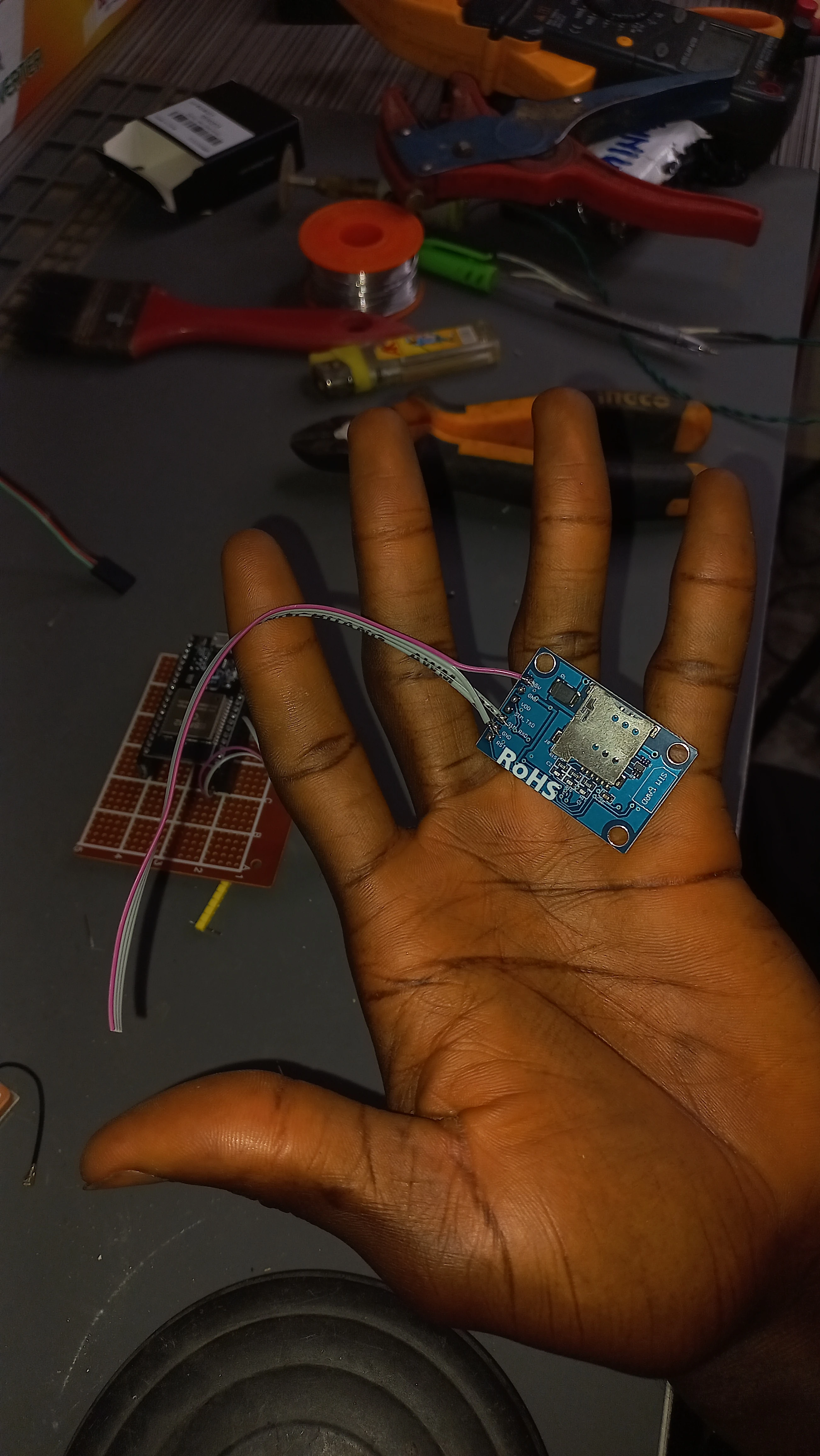
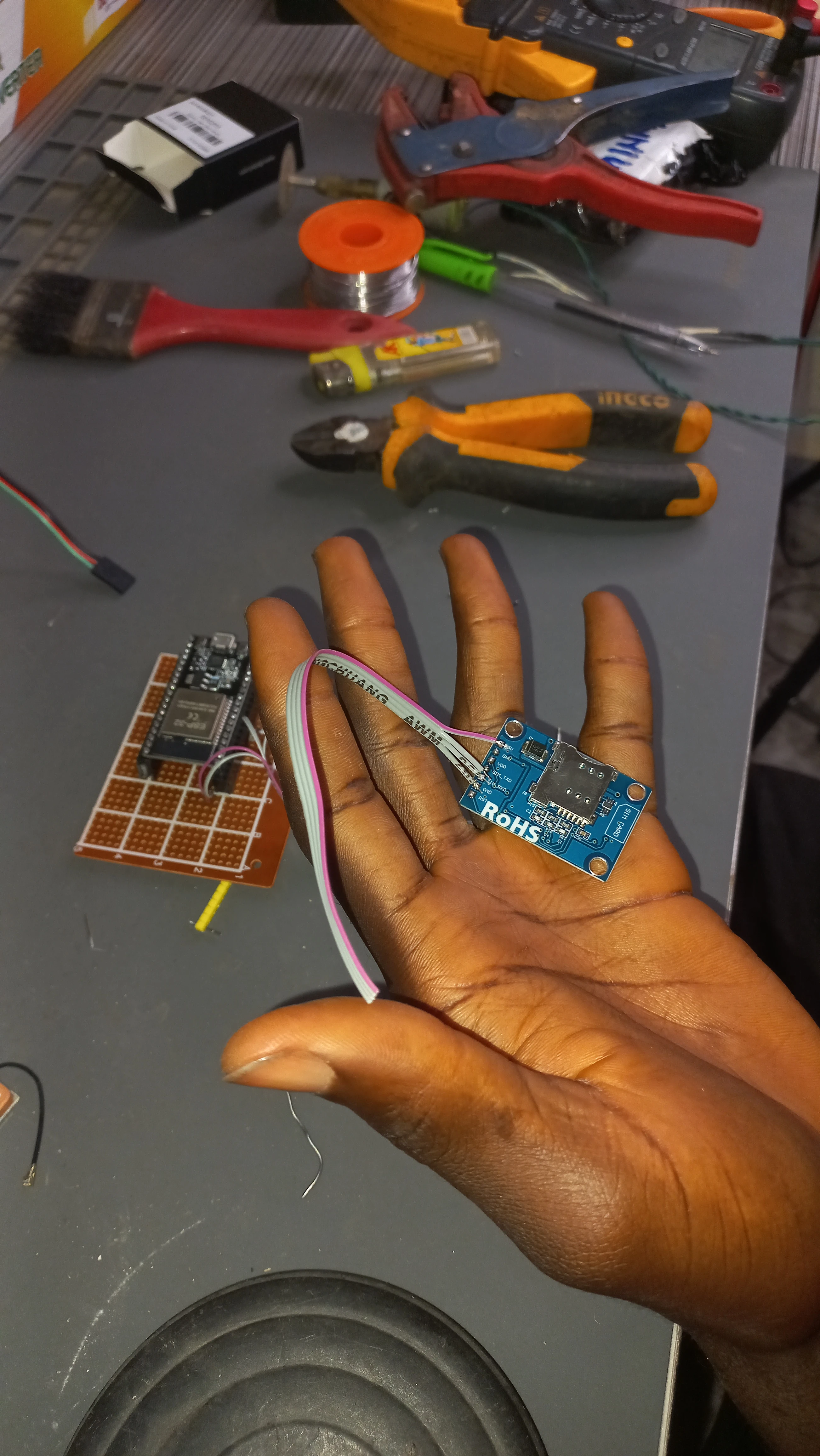
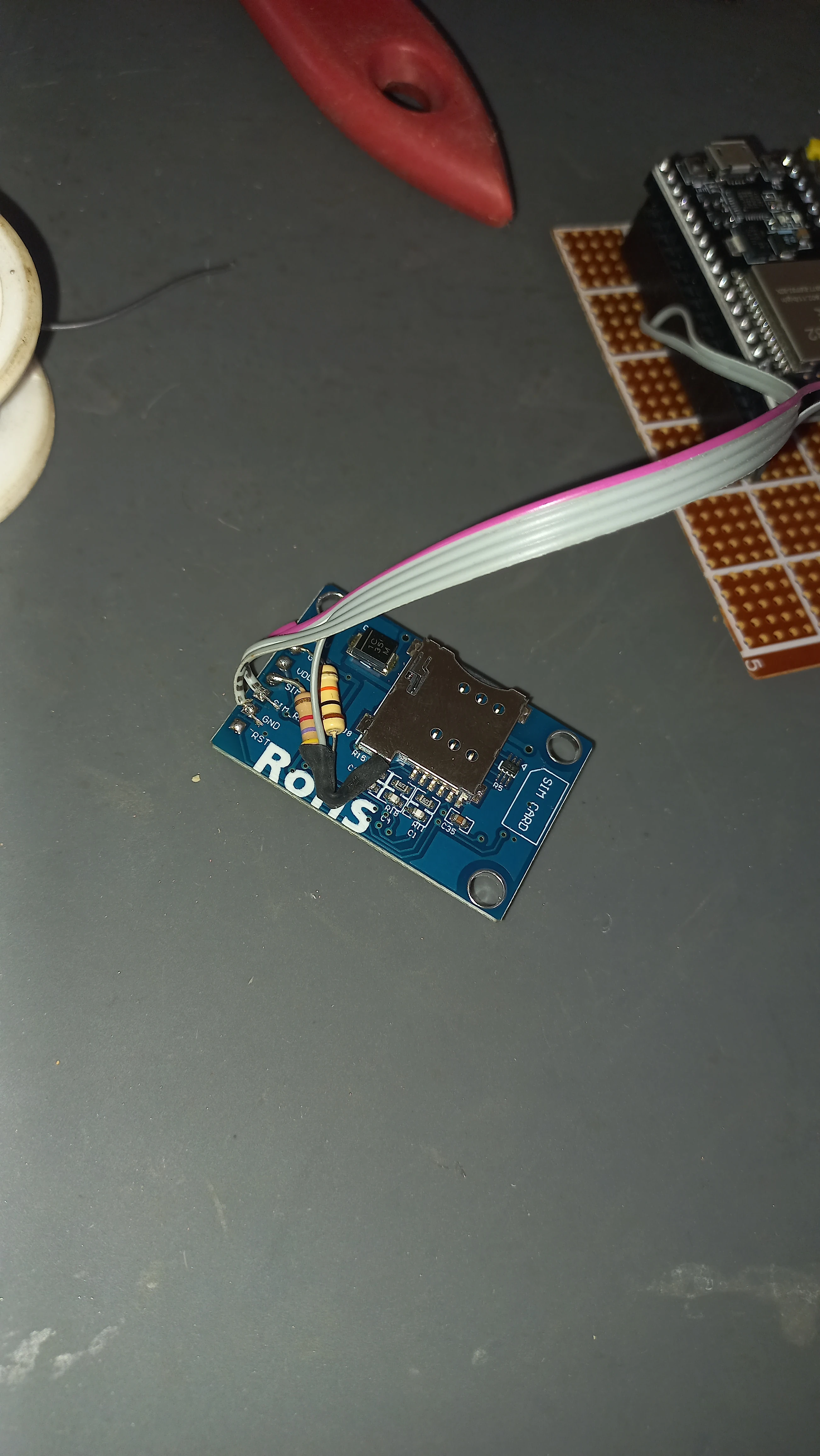
| GSM Module | SIM800L EVB with whip antenna & u.FL pigtail | SMS dispatch over UART1 via AT commands |
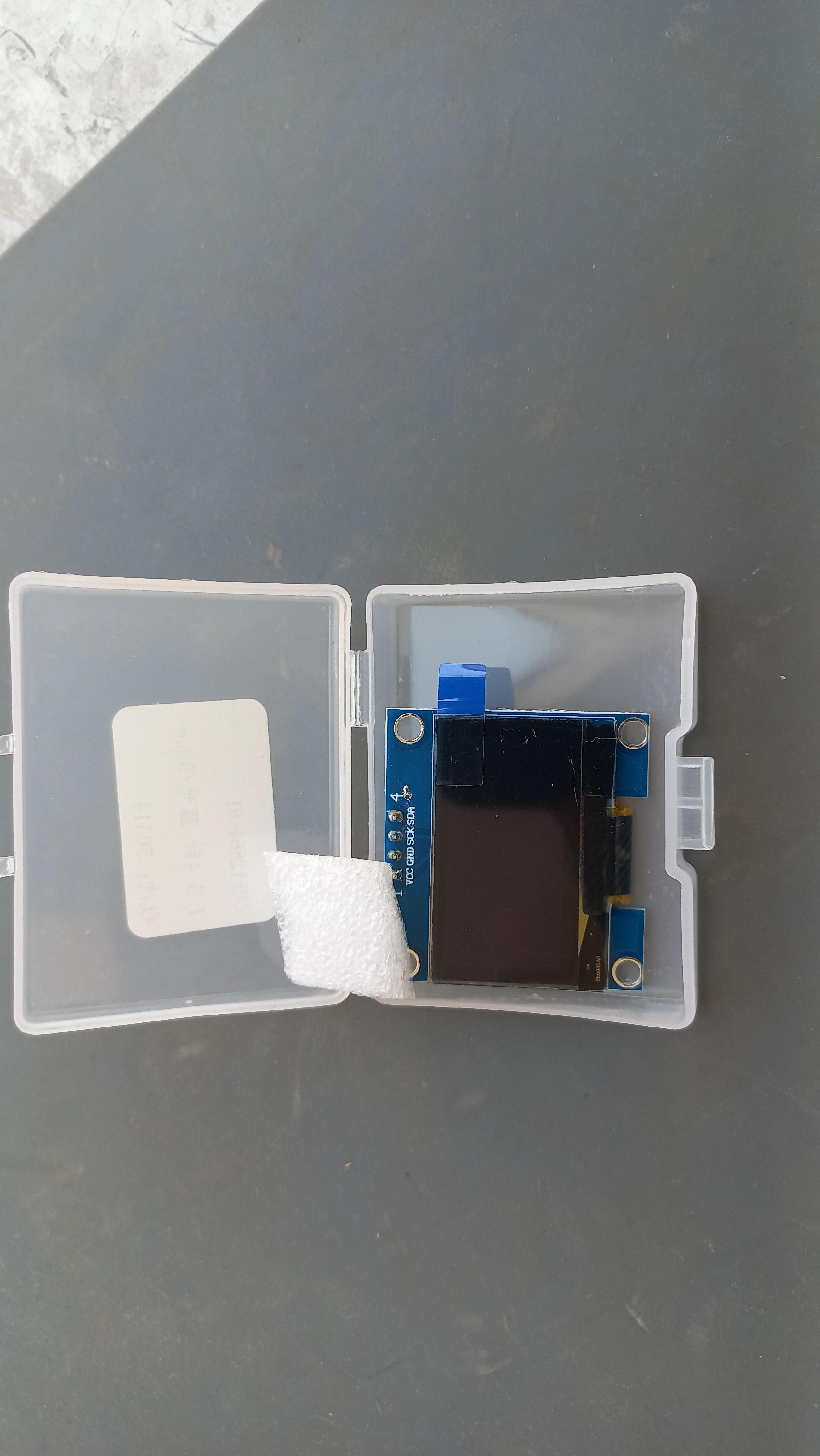
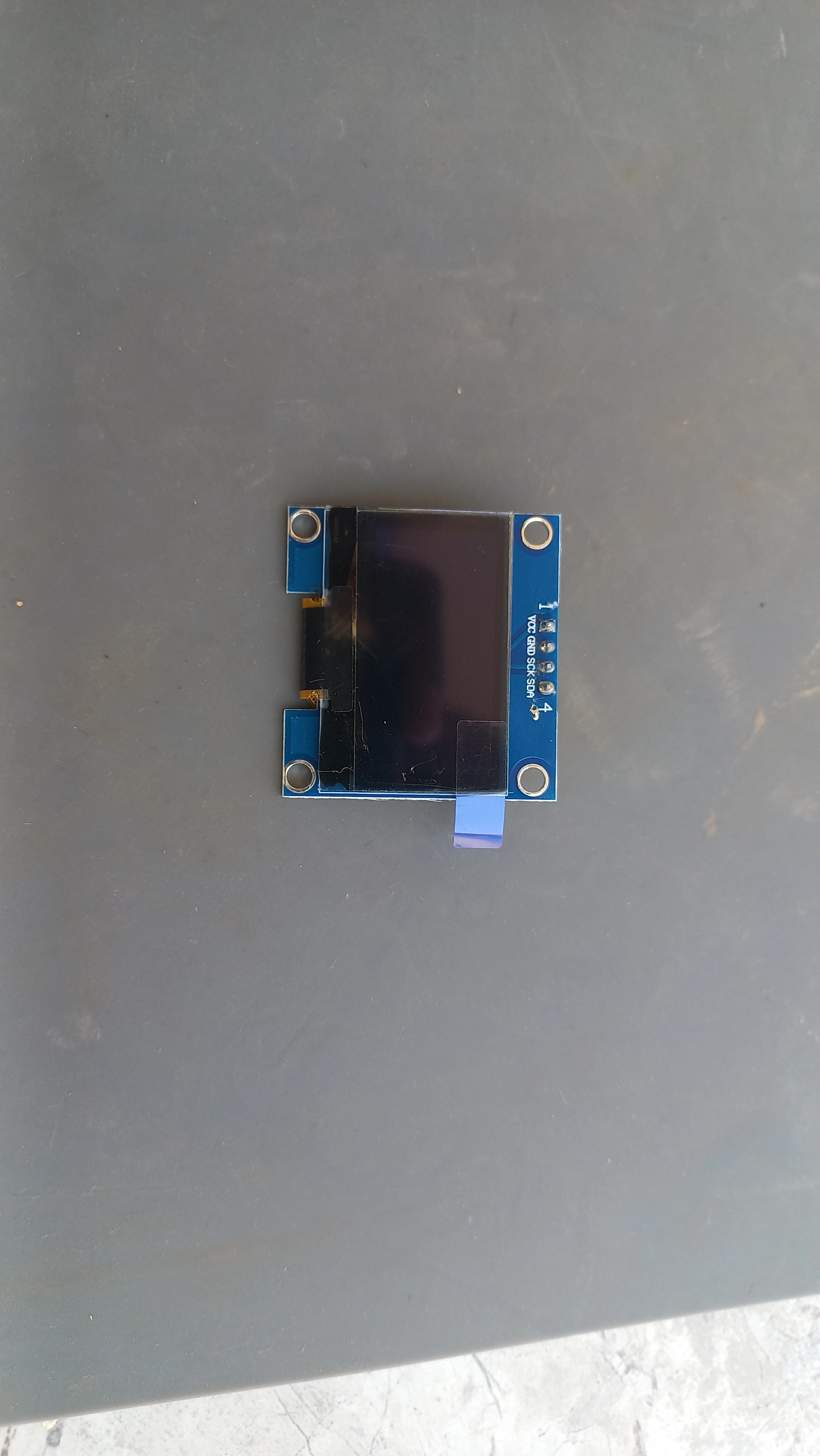
| OLED Display | SH1106 1.3” 128×64 I2C | Live dashboard (mode, BPM, GPS) via U8g2 library |
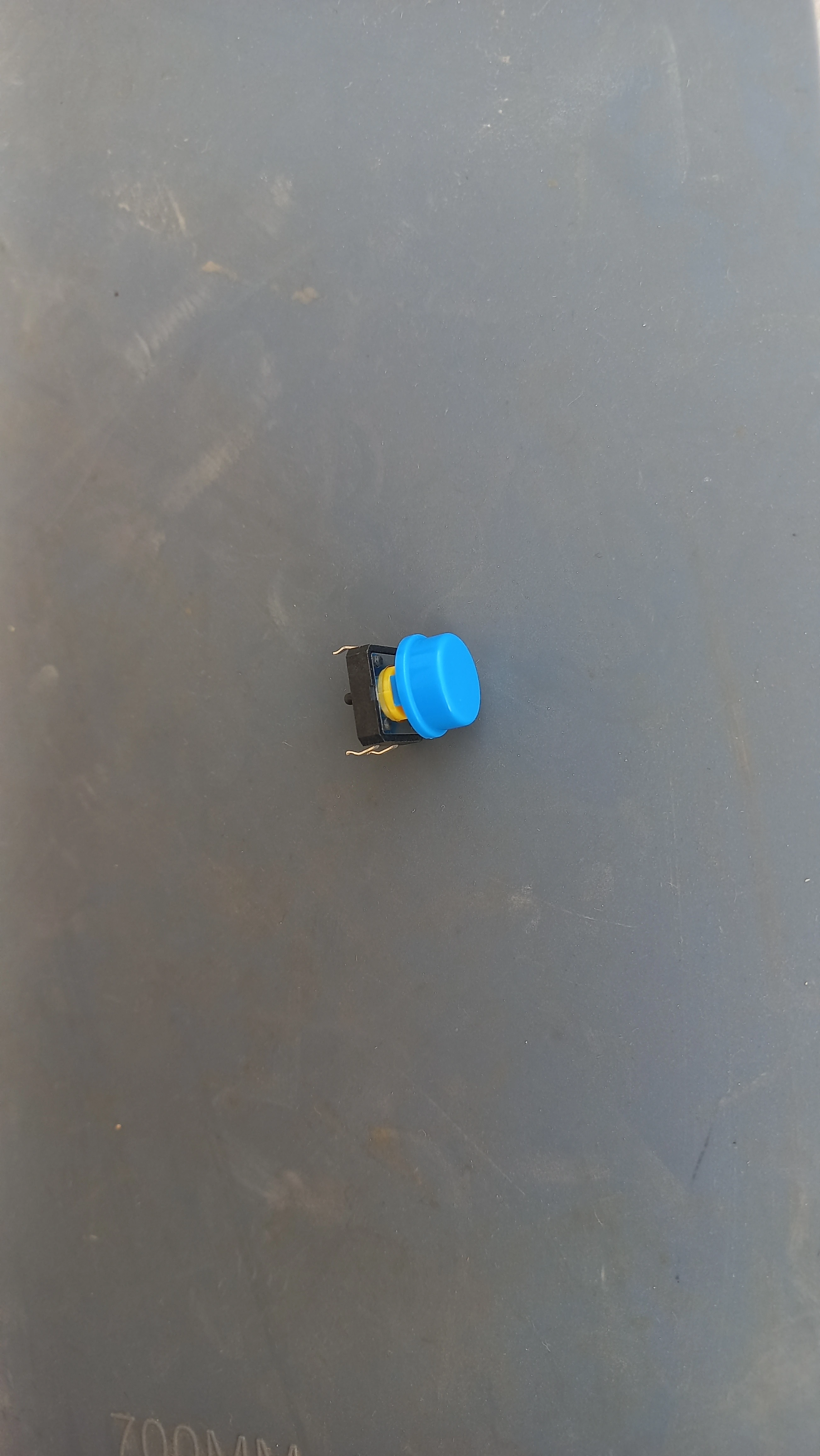
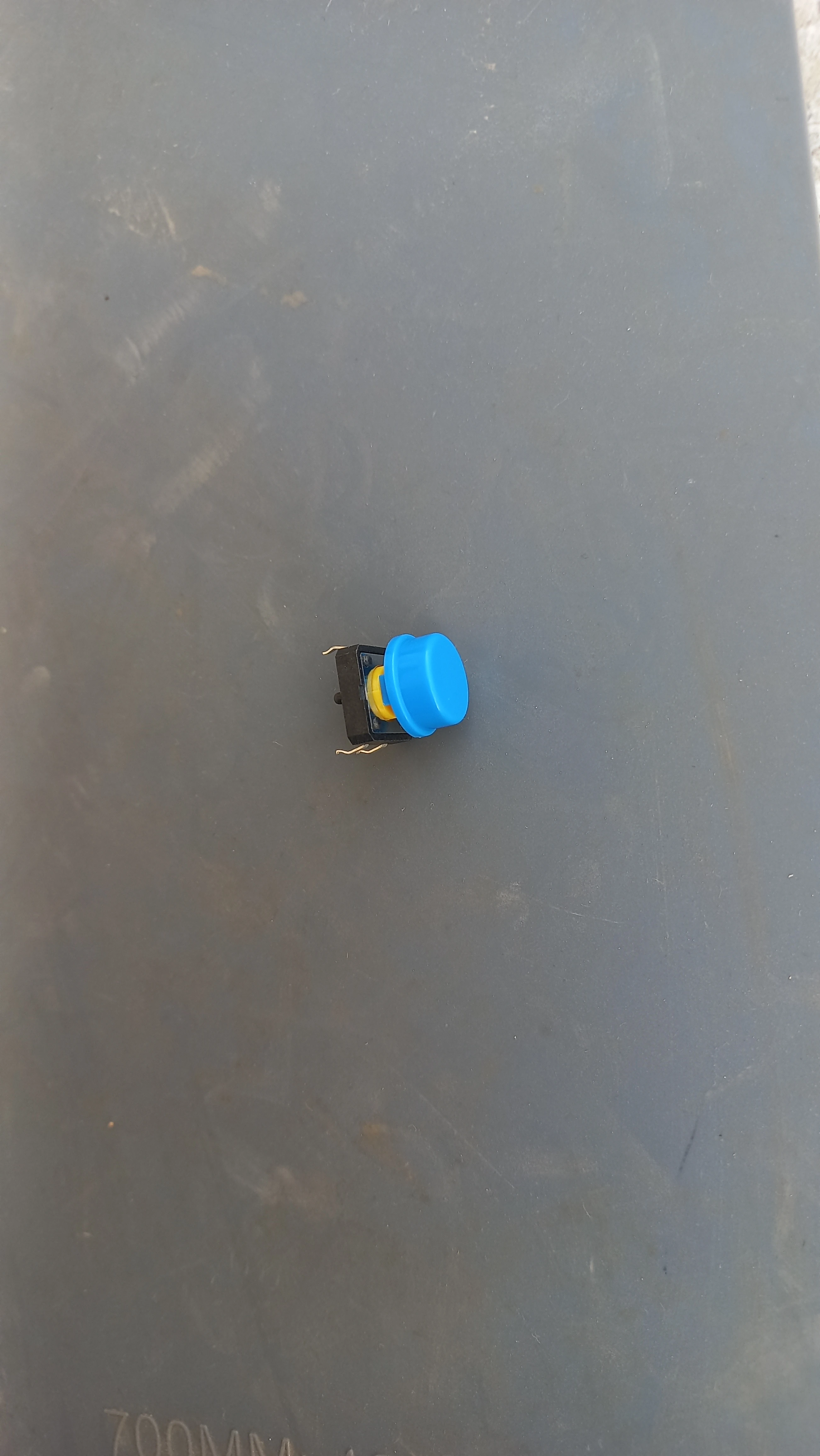
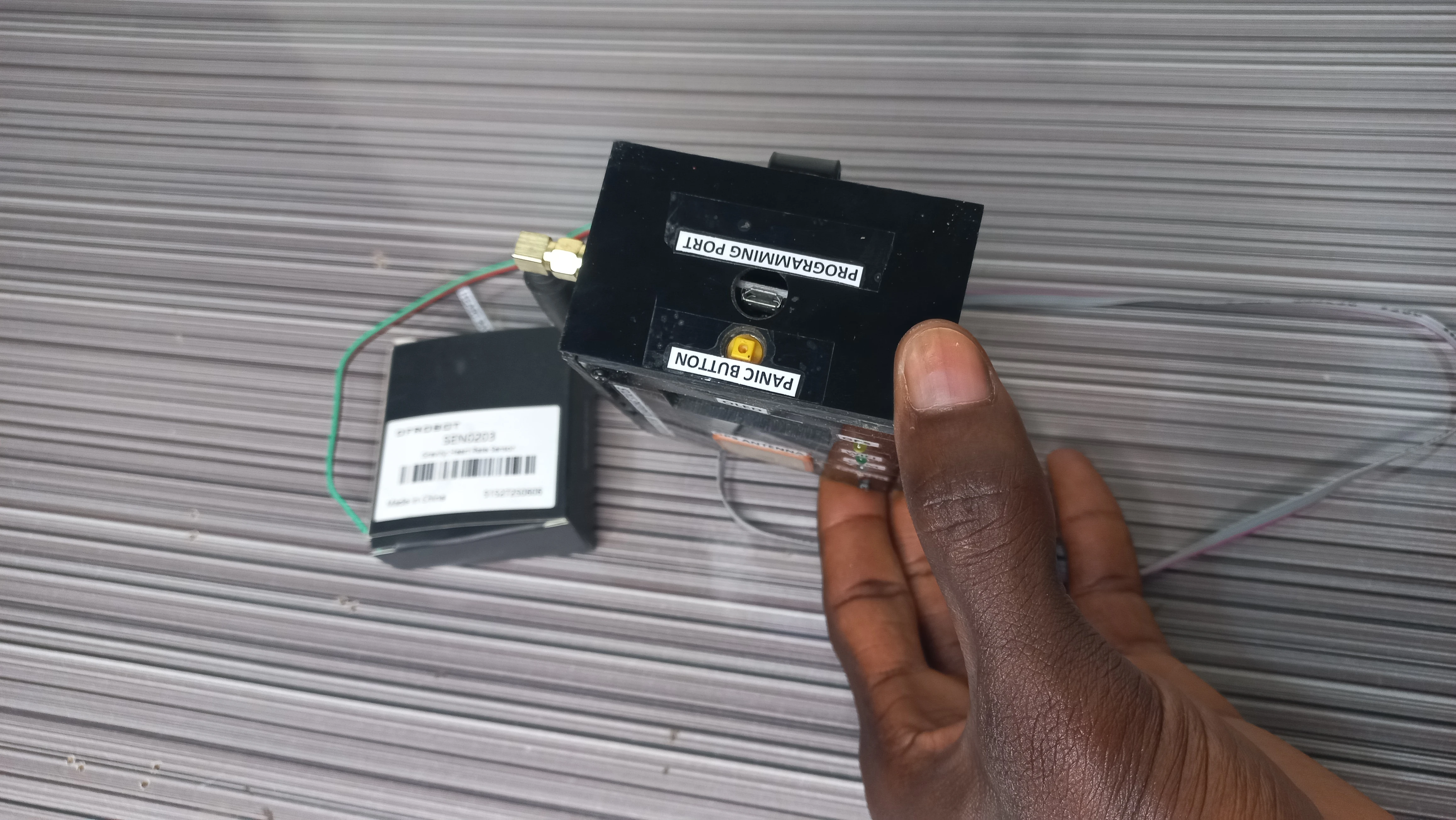
| Panic Button | Blue tactile push button (GPIO 5, INPUT_PULLUP) | Short press = danger trigger; long press = safe reset |
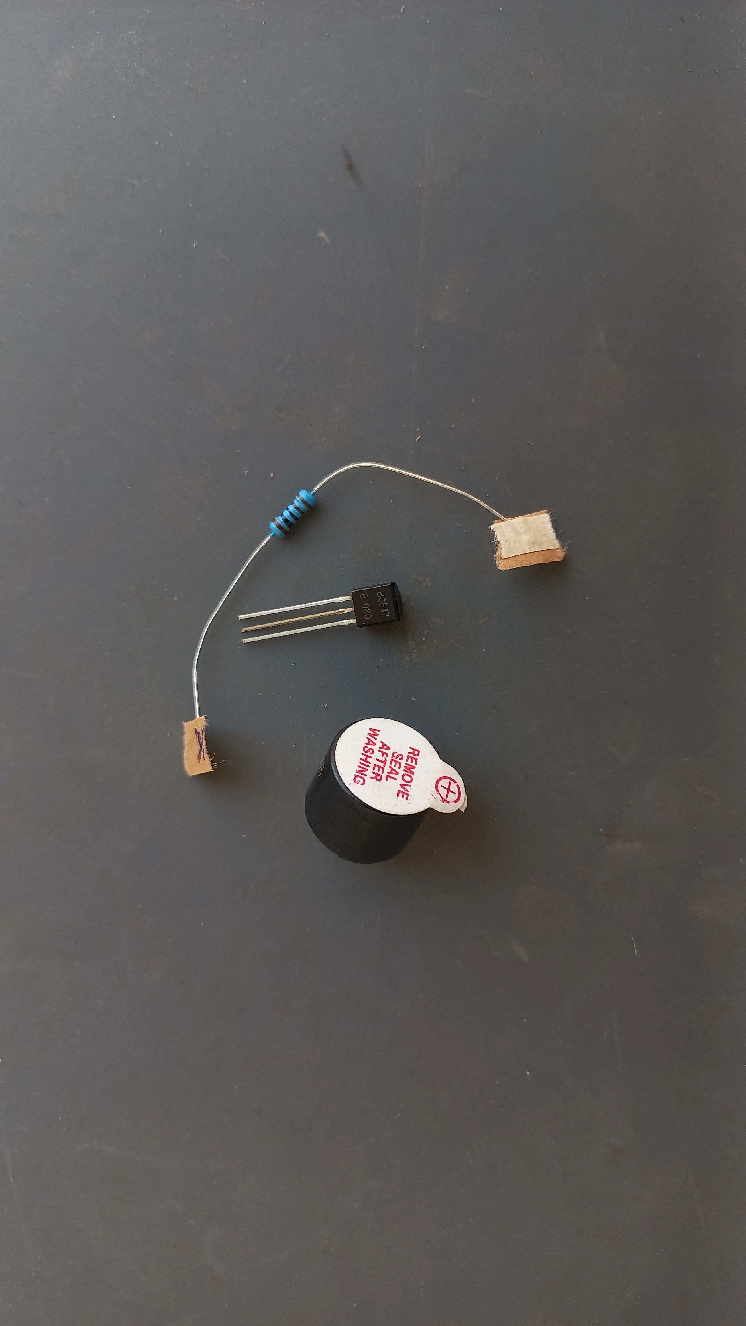
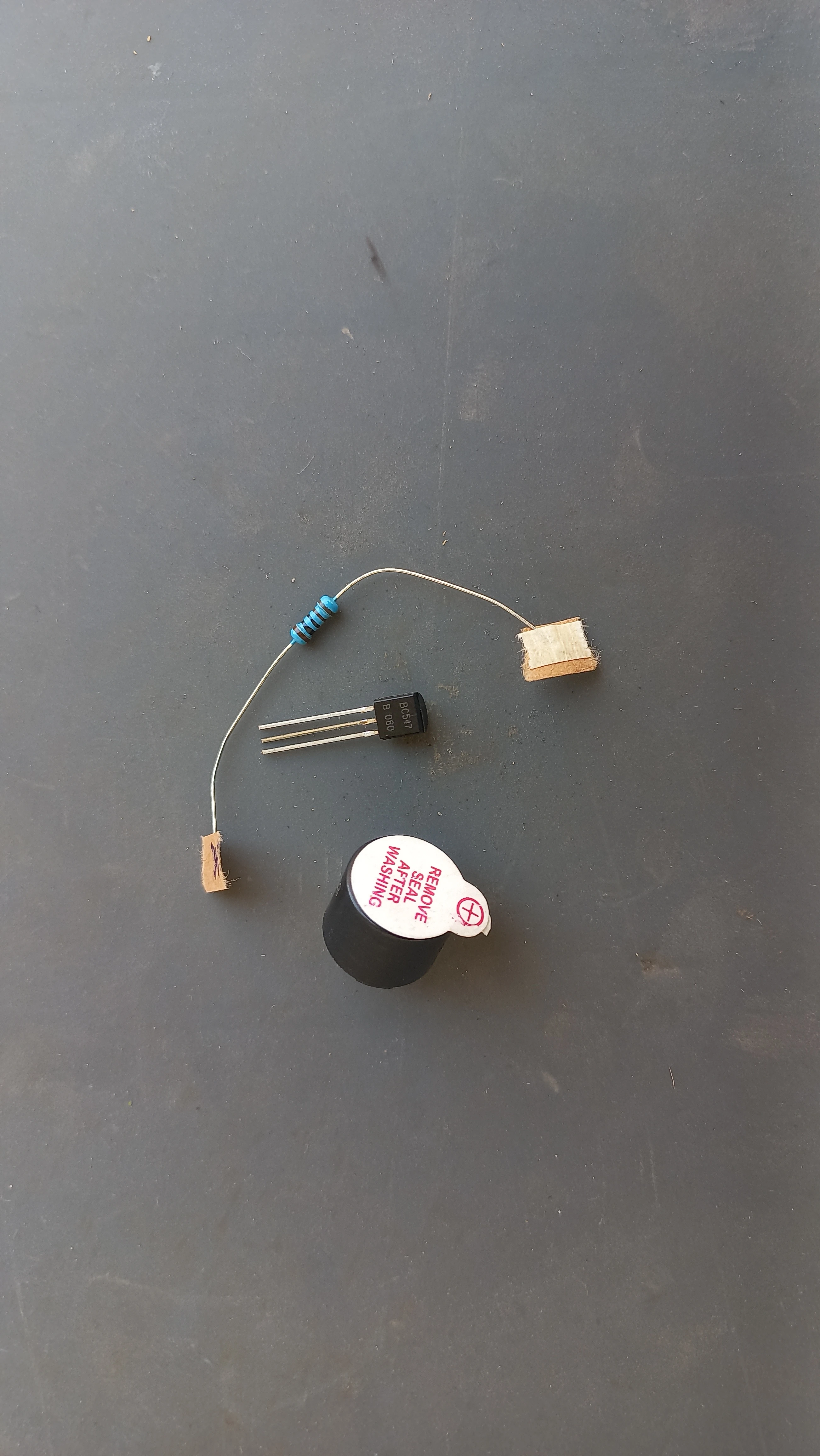
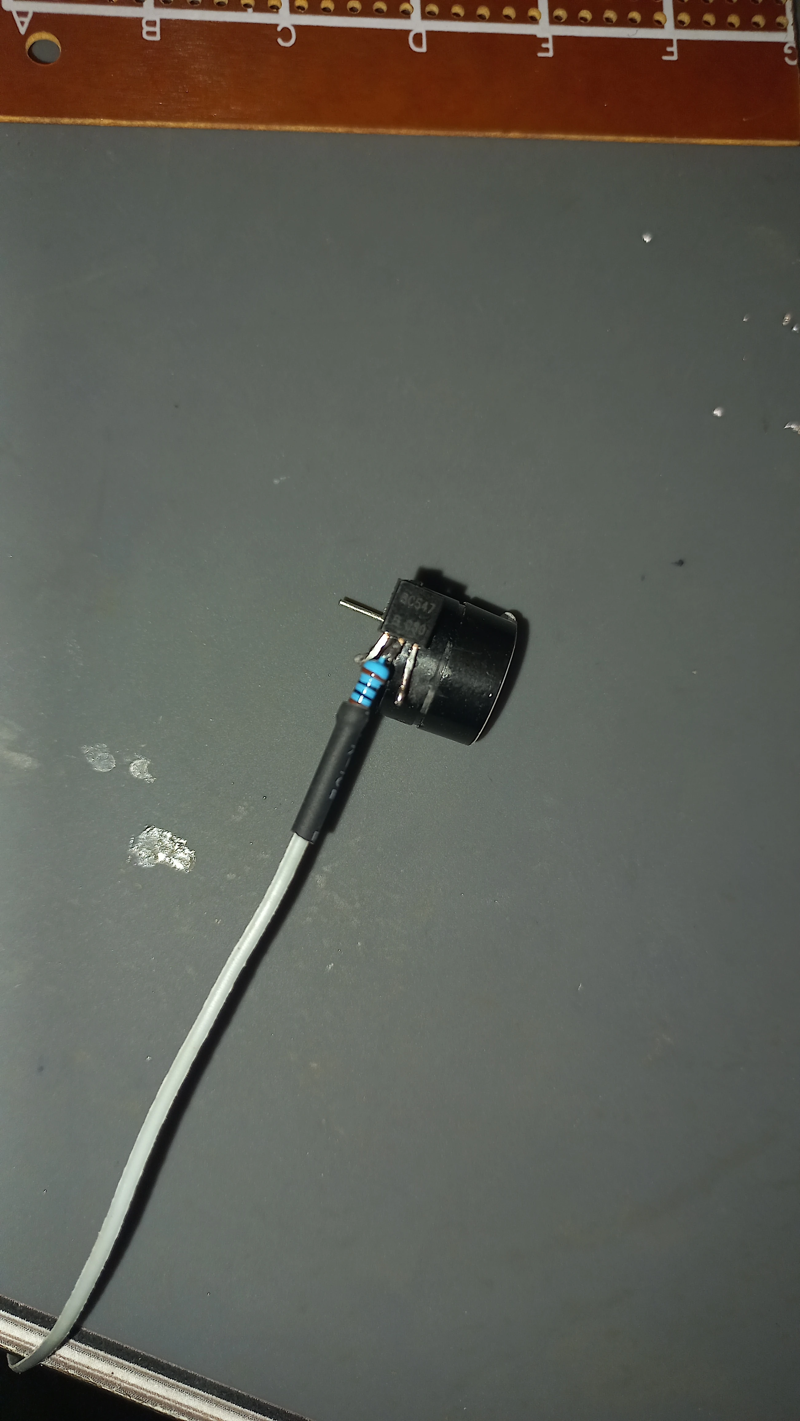
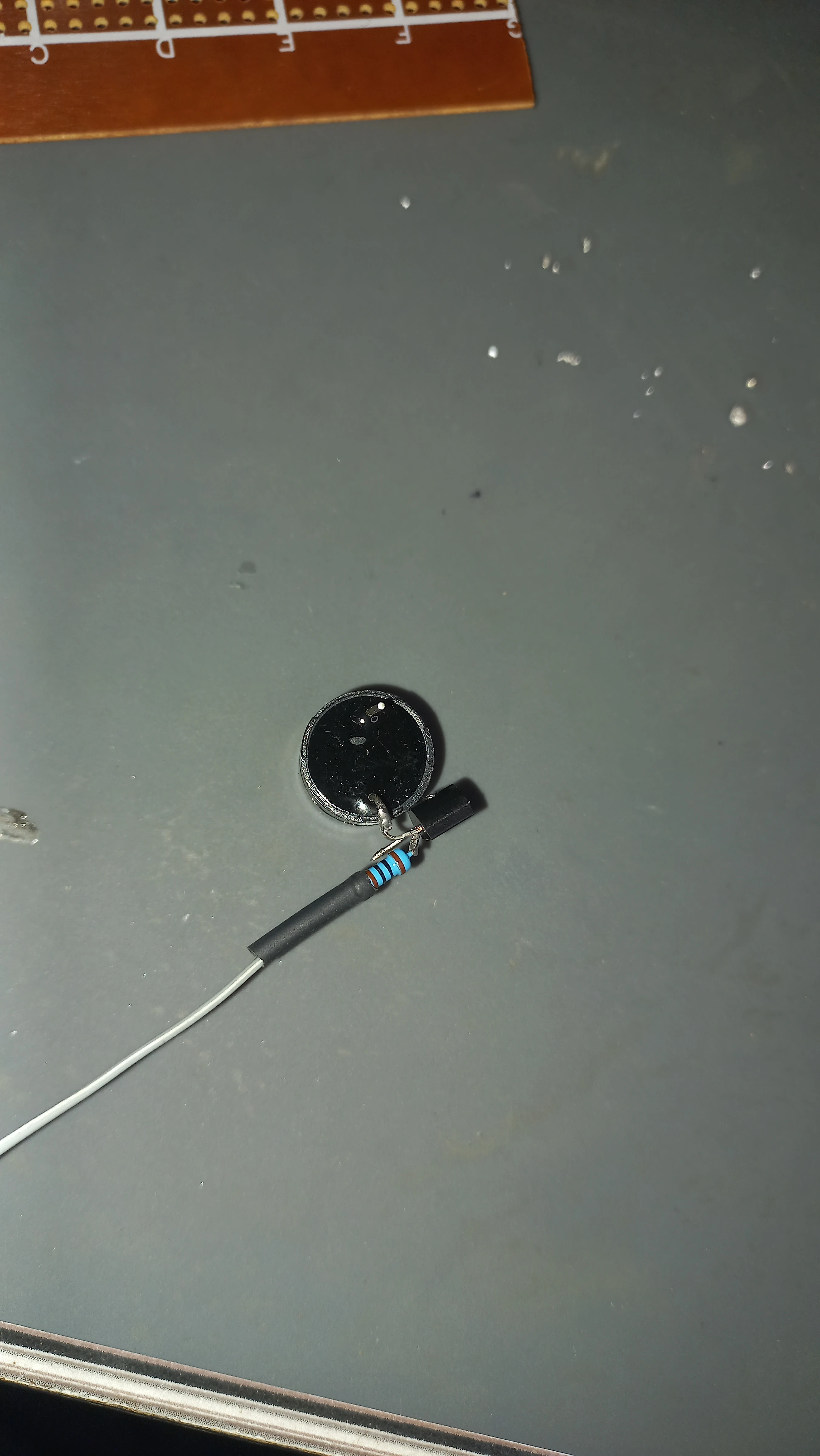
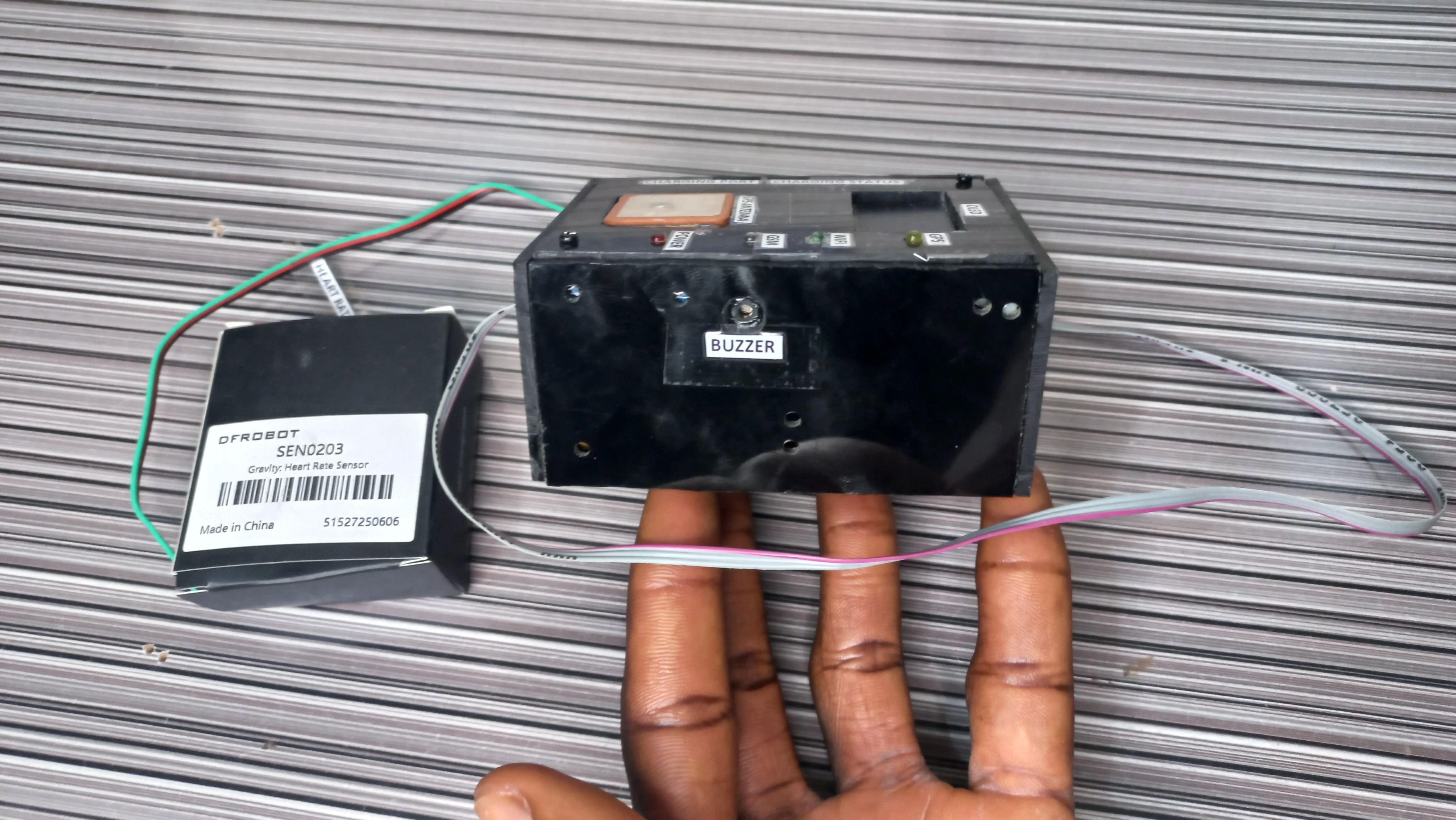
| Buzzer | Active buzzer + BC547 NPN transistor driver | 3-beep audible alert pattern while in DANGER mode |
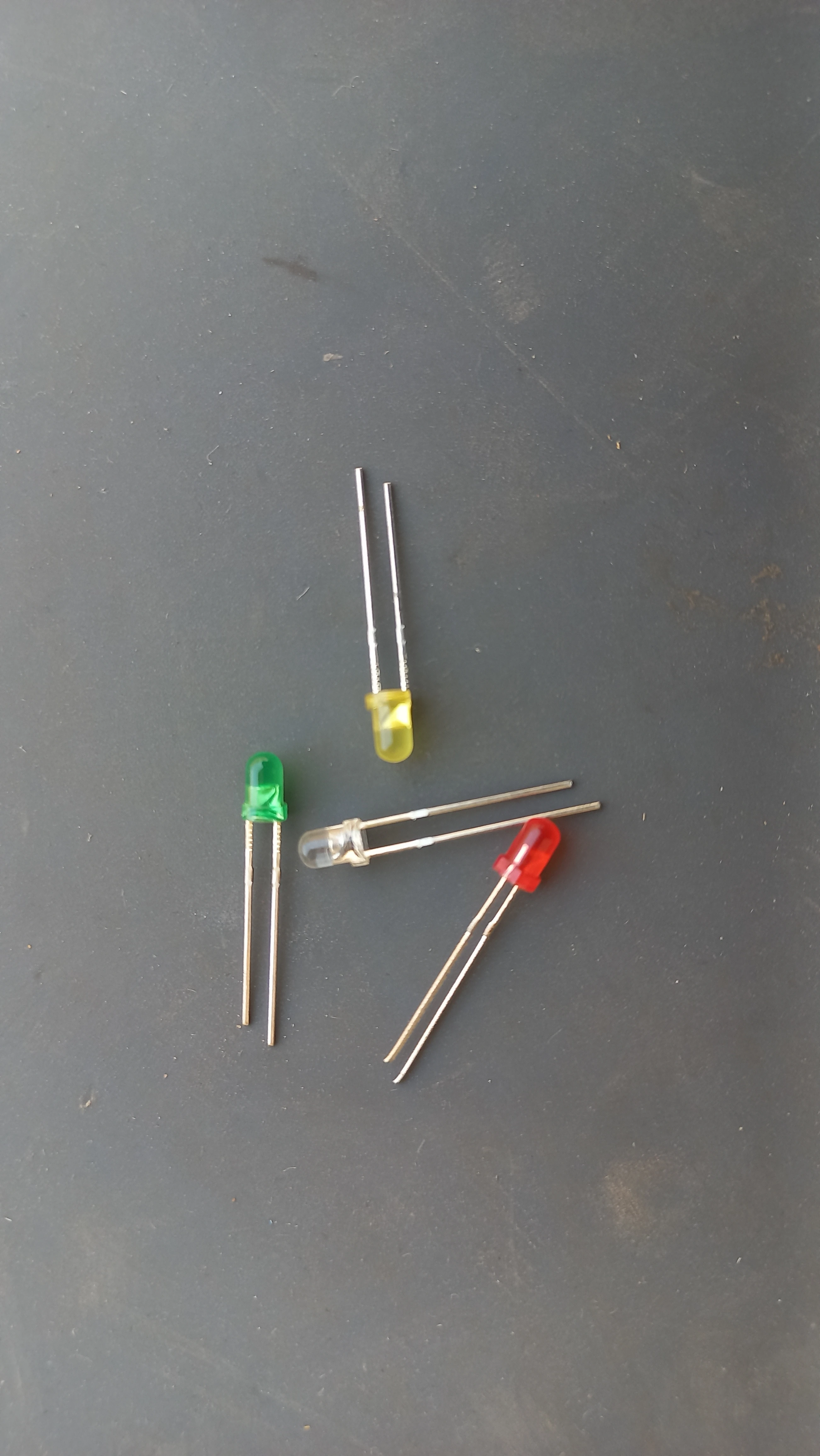
| Status LEDs | Green (Wi-Fi GPIO 19), Yellow (GPS GPIO 4) | Visual connectivity indicators |
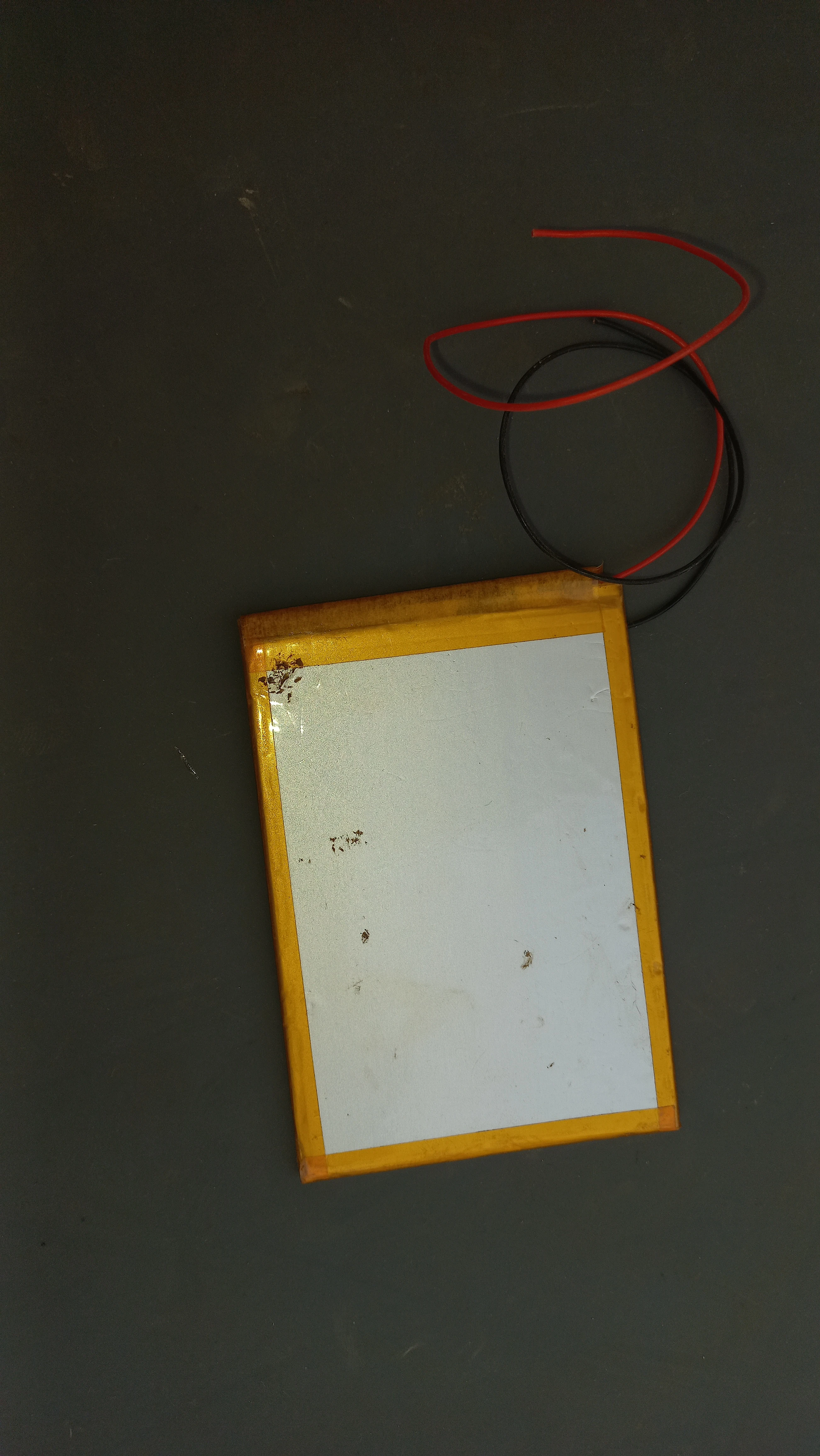
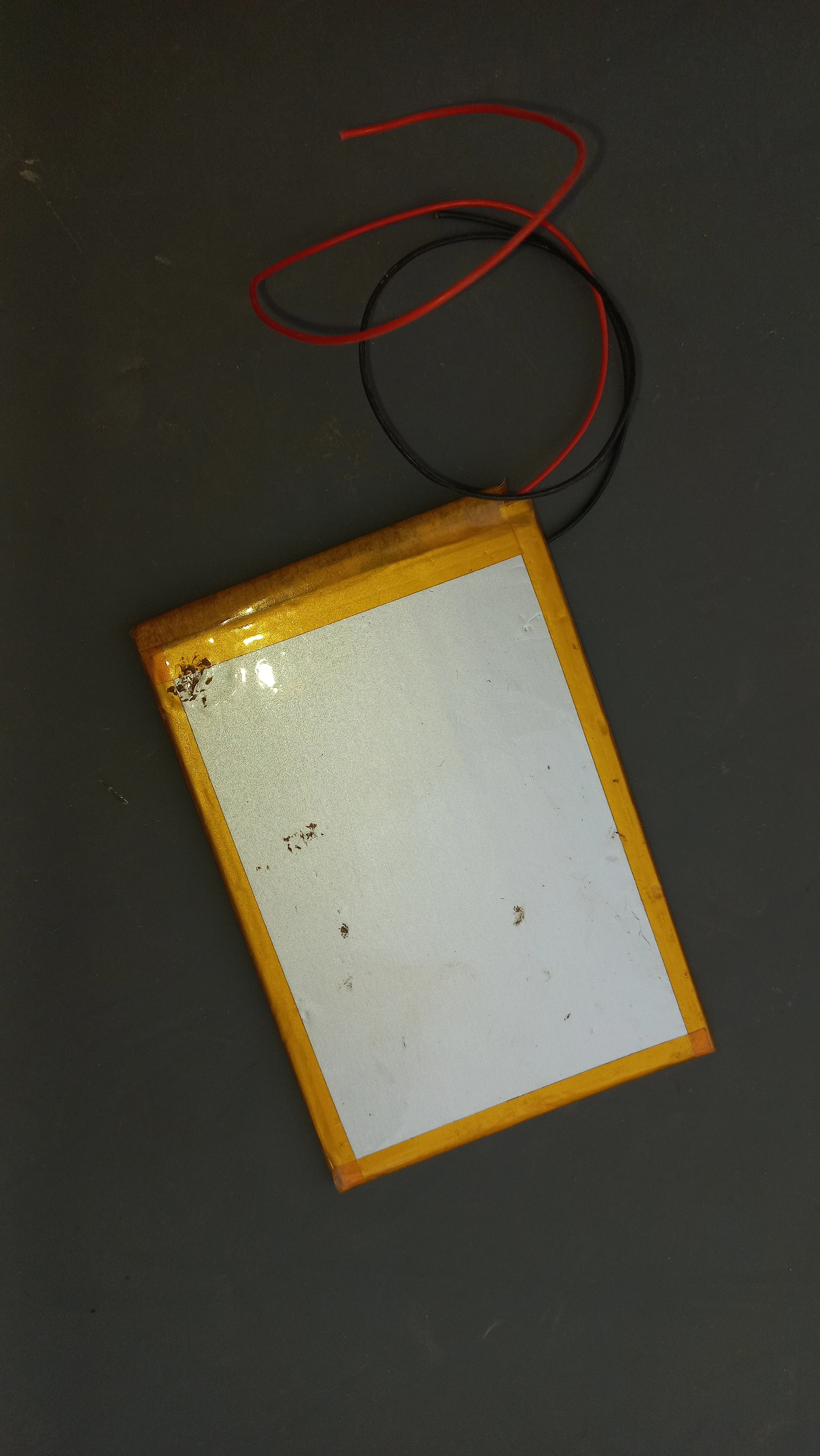
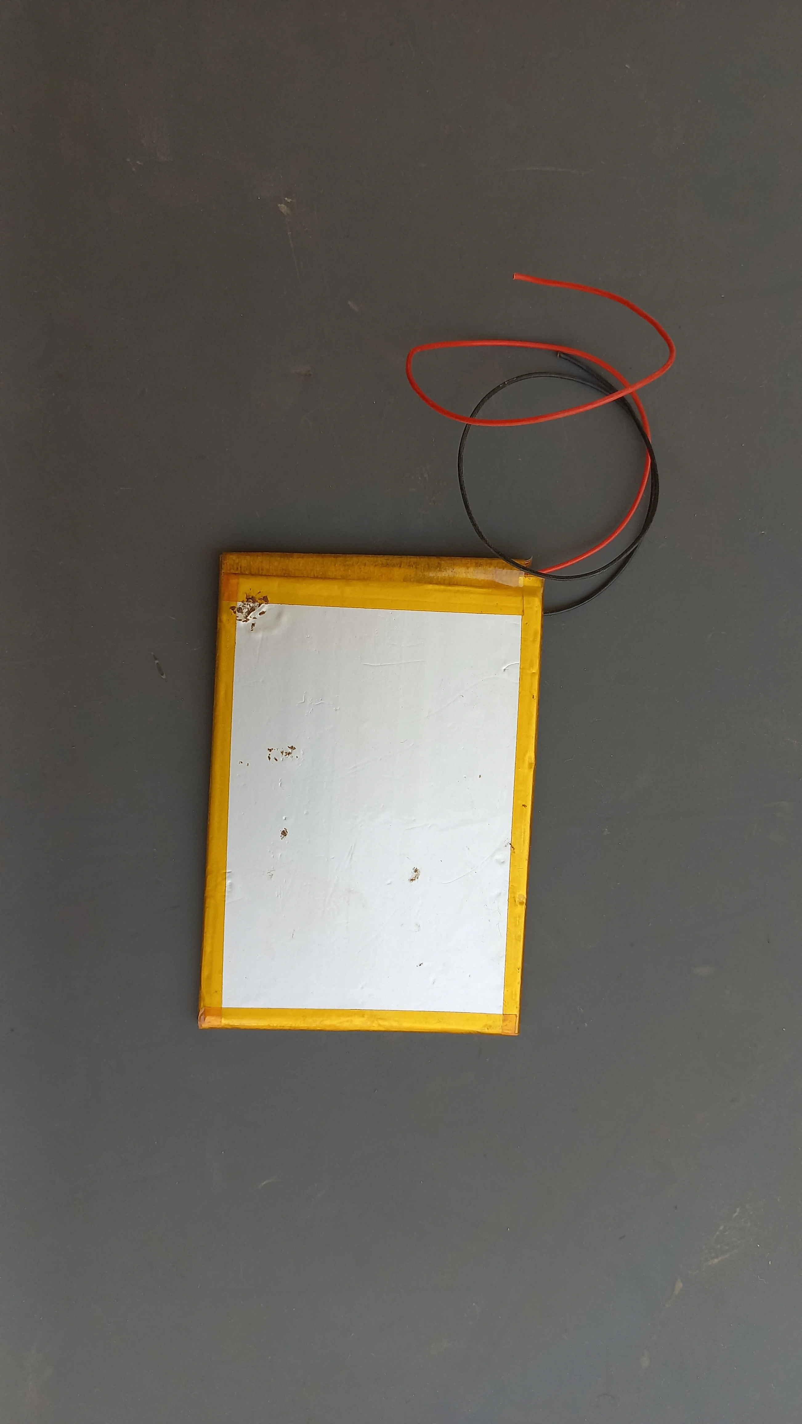
| LiPo Battery | 3.7 V LiPo (red/black wires) | Primary portable power source |
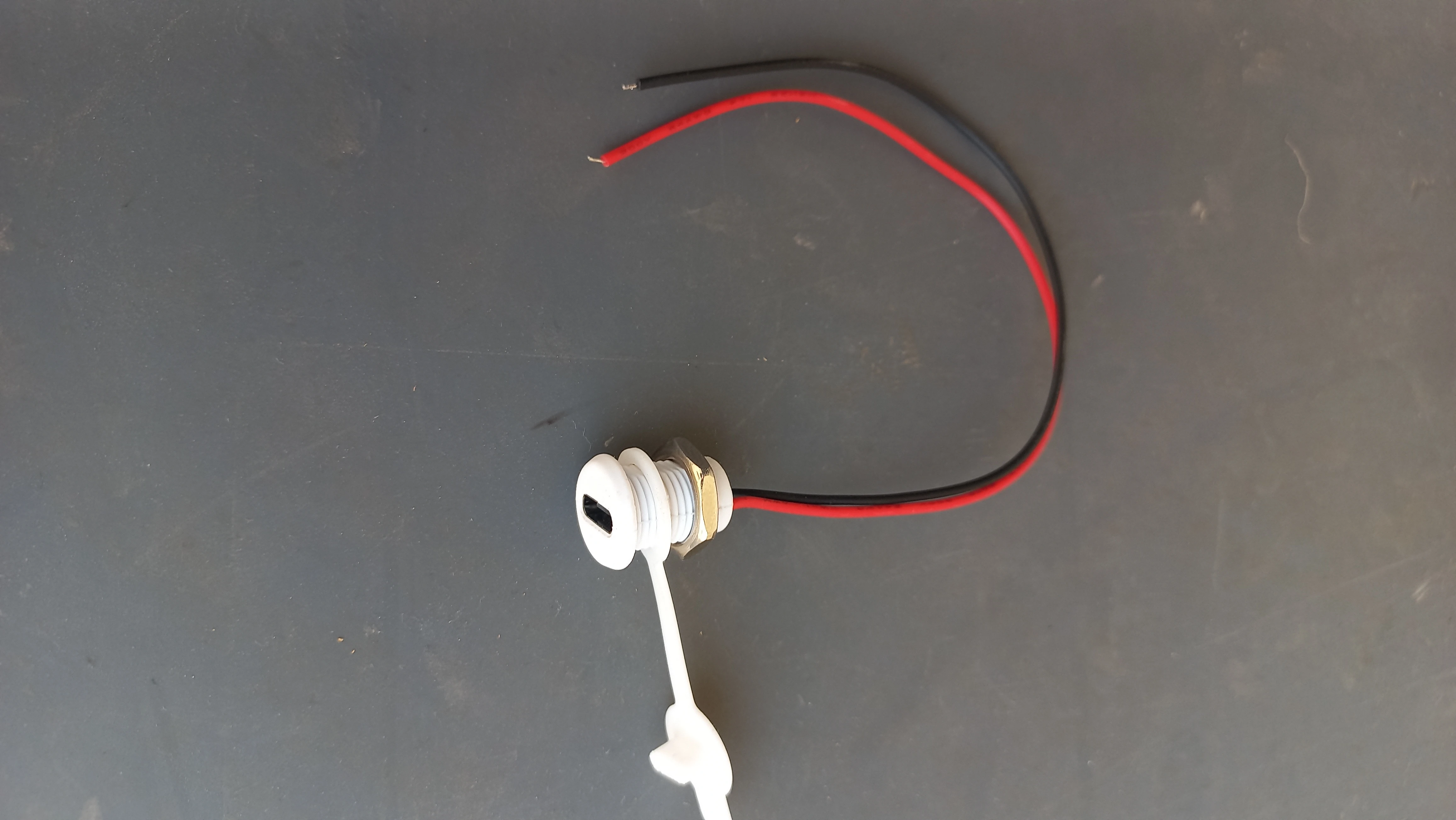
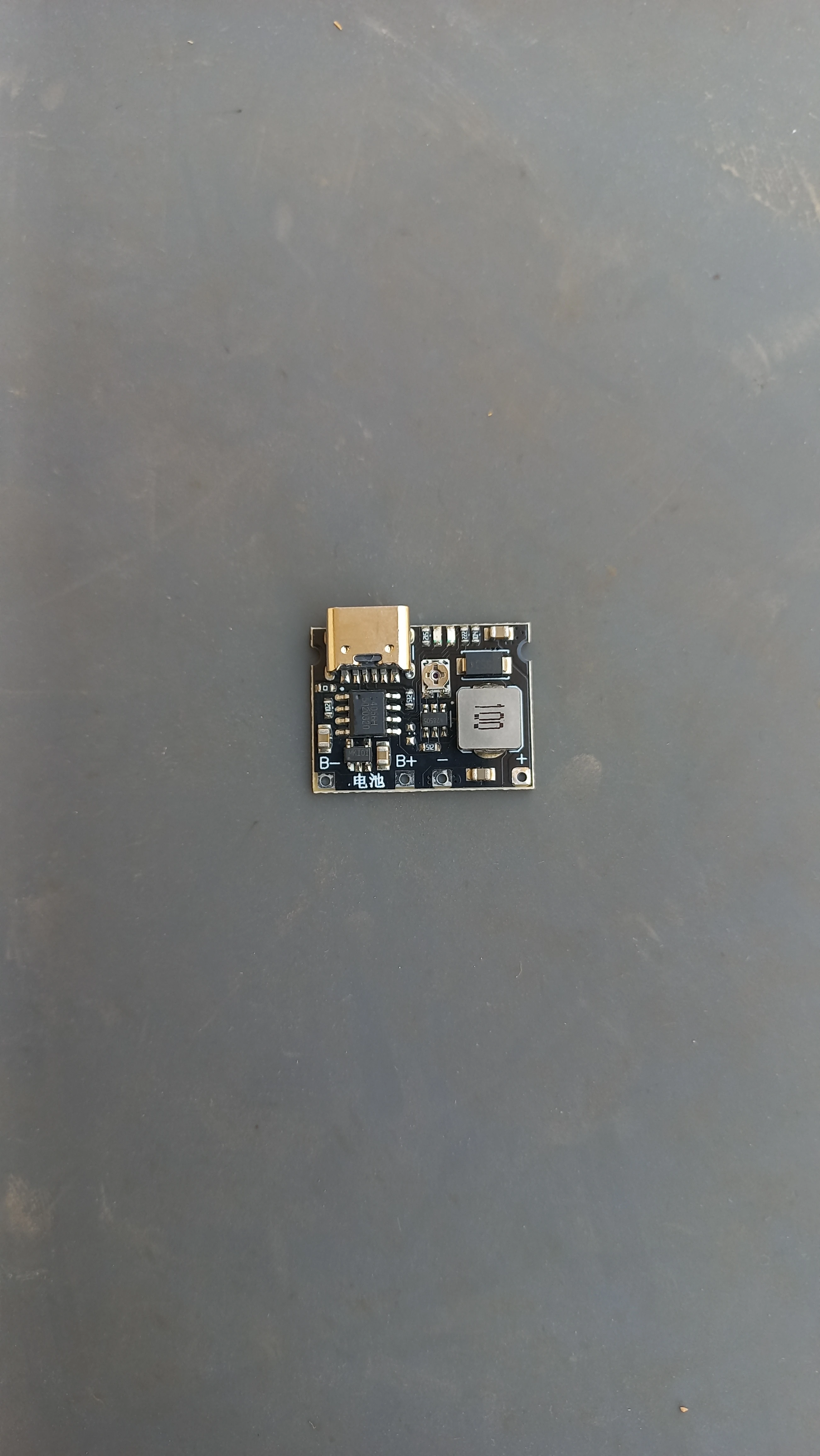
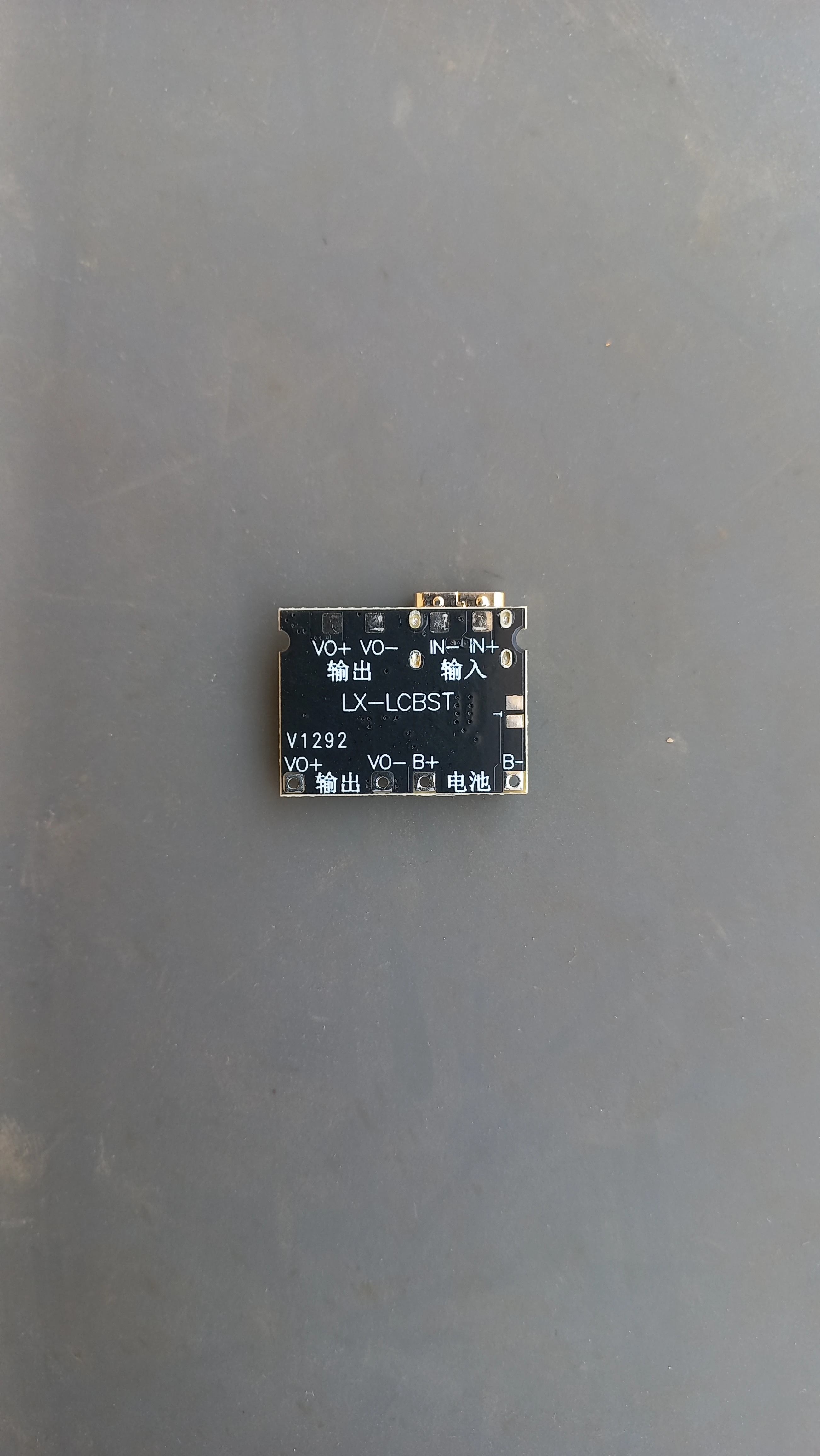
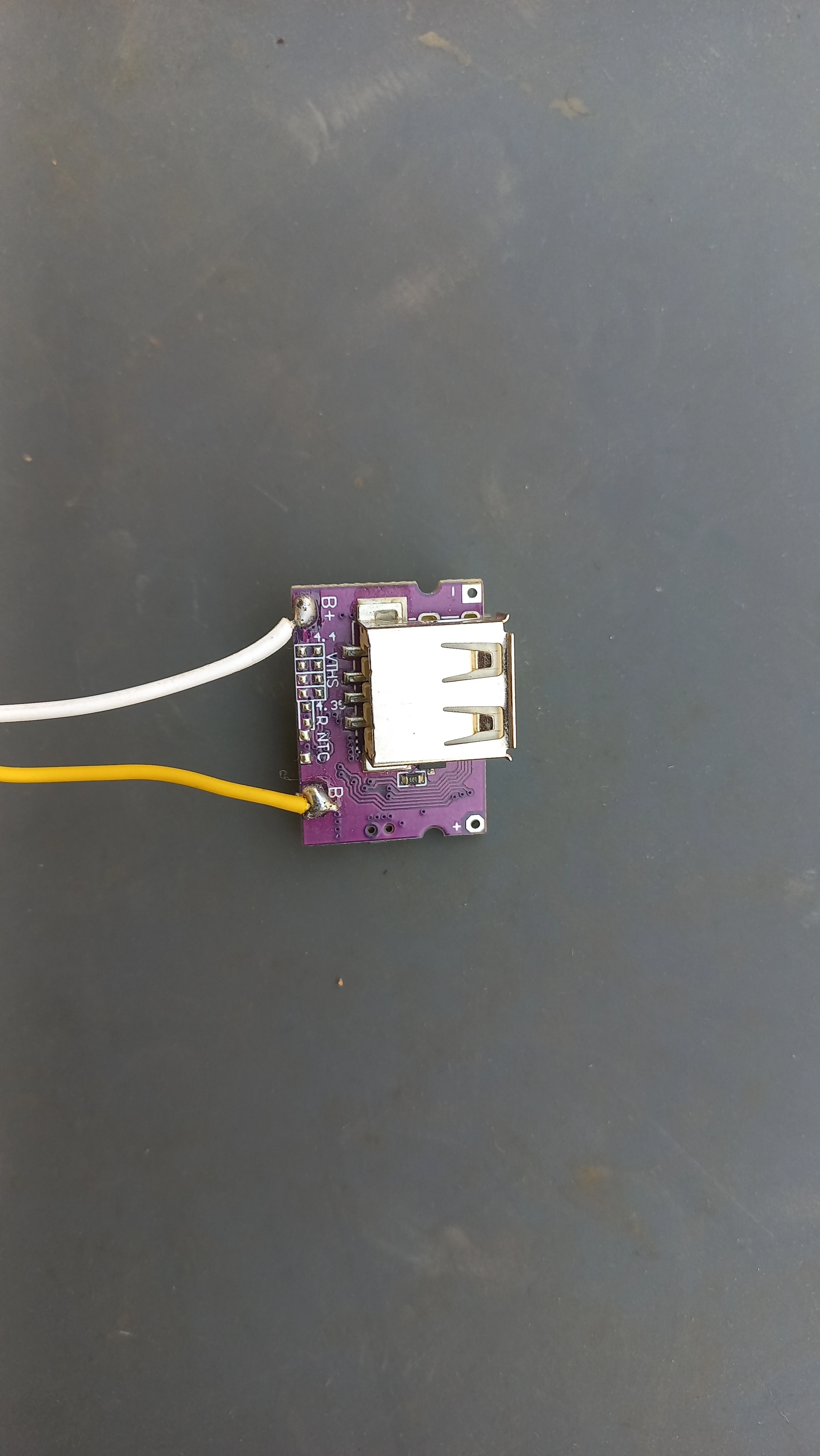
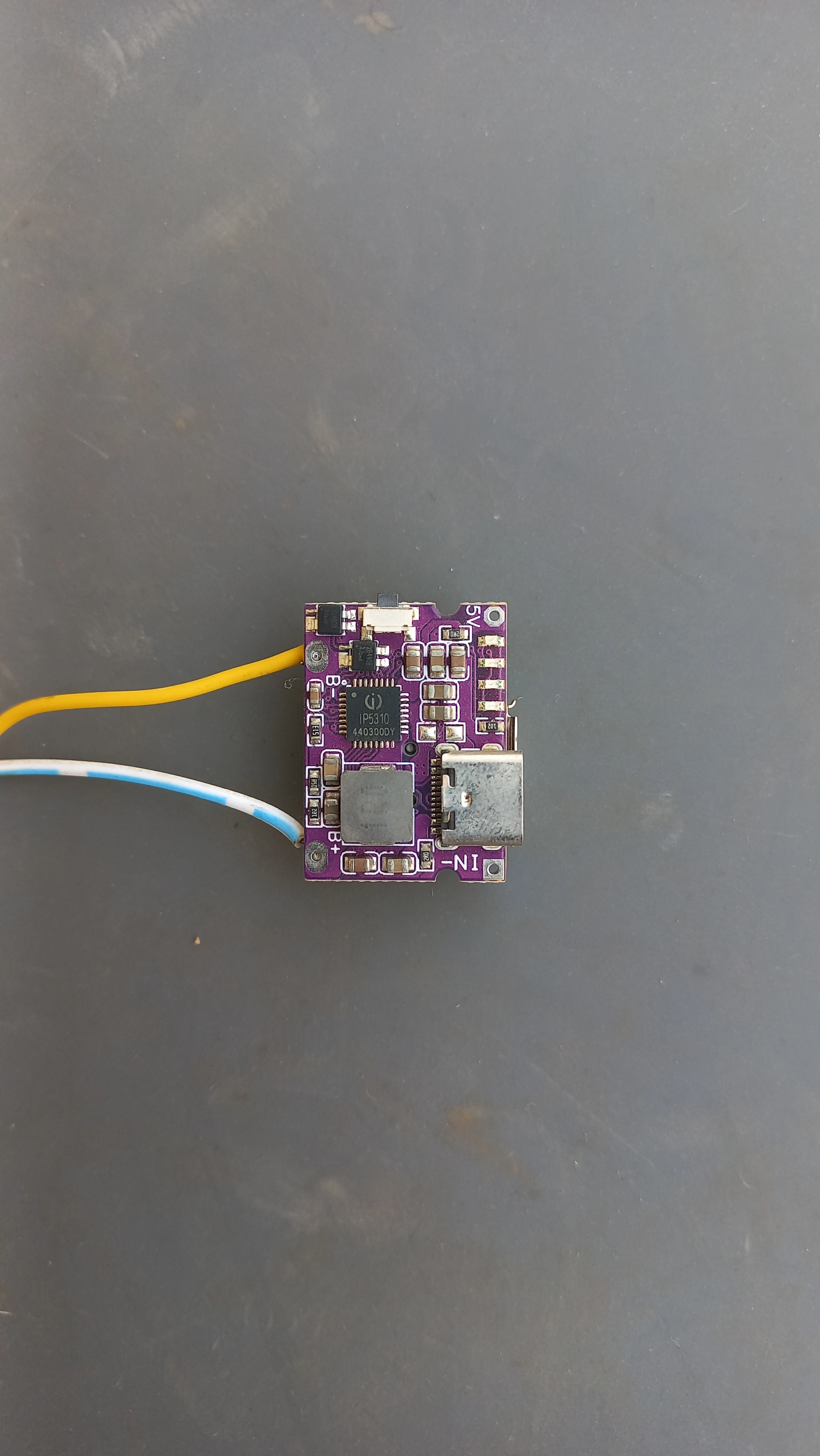
| Charger Module | LX-LCBST USB-C LiPo charger | Charging management with indicator LEDs |
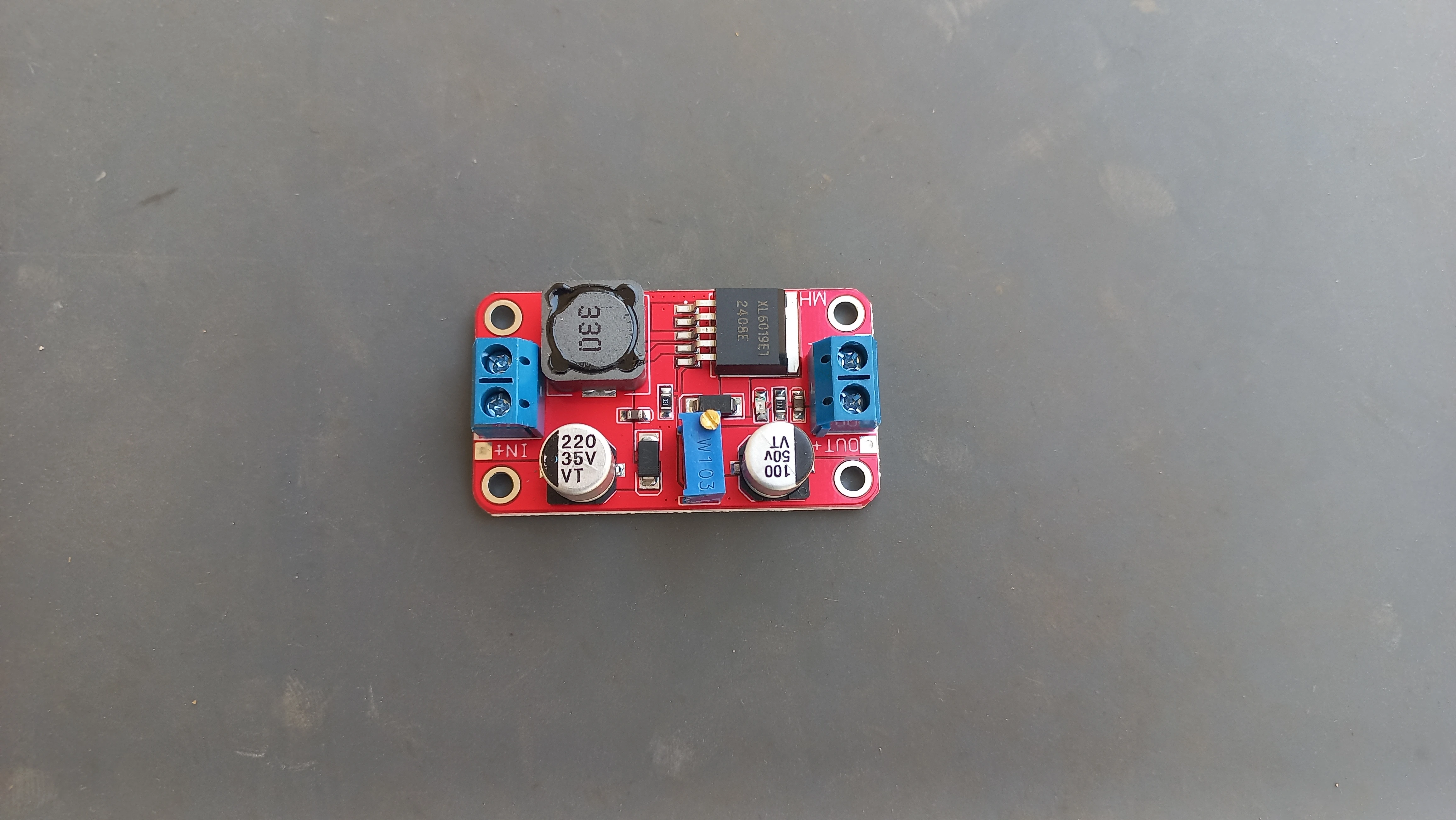
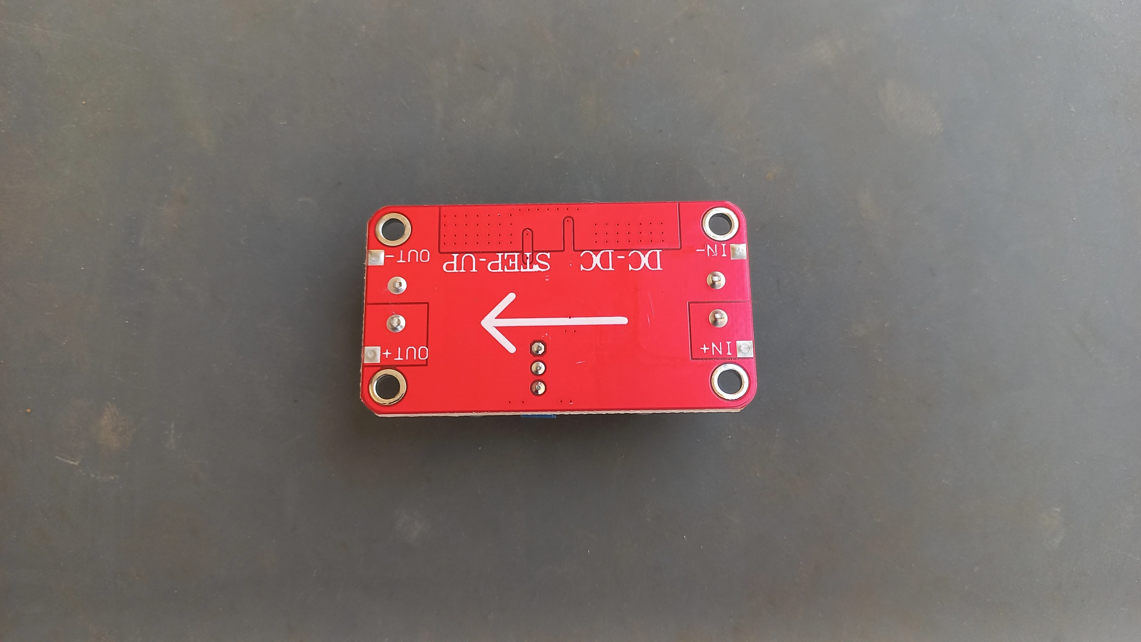
| Boost Converter | XL6009 DC-DC step-up module | Boosts LiPo 3.7 V to stable 5 V rail for ESP32 & peripherals |
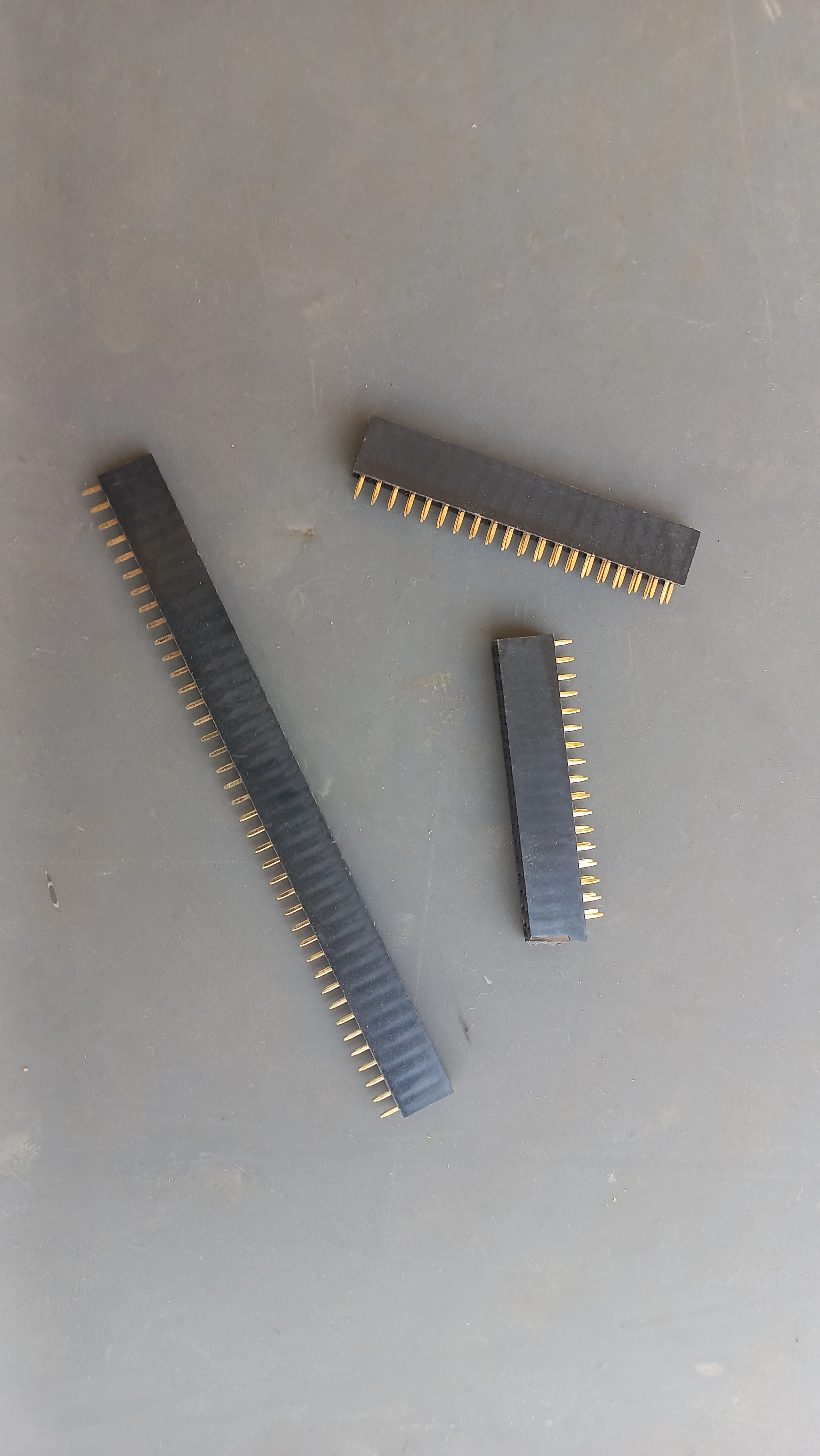
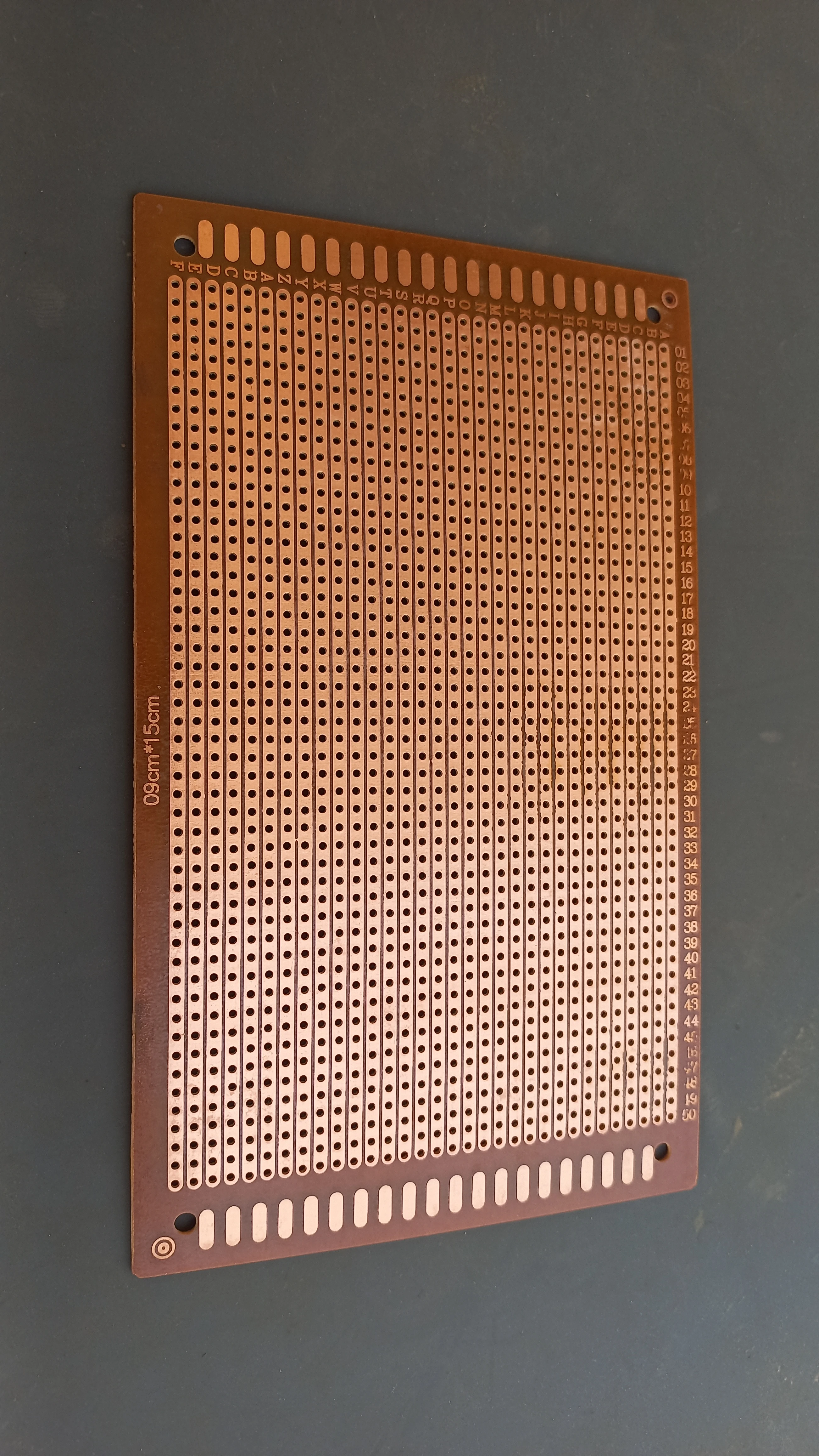
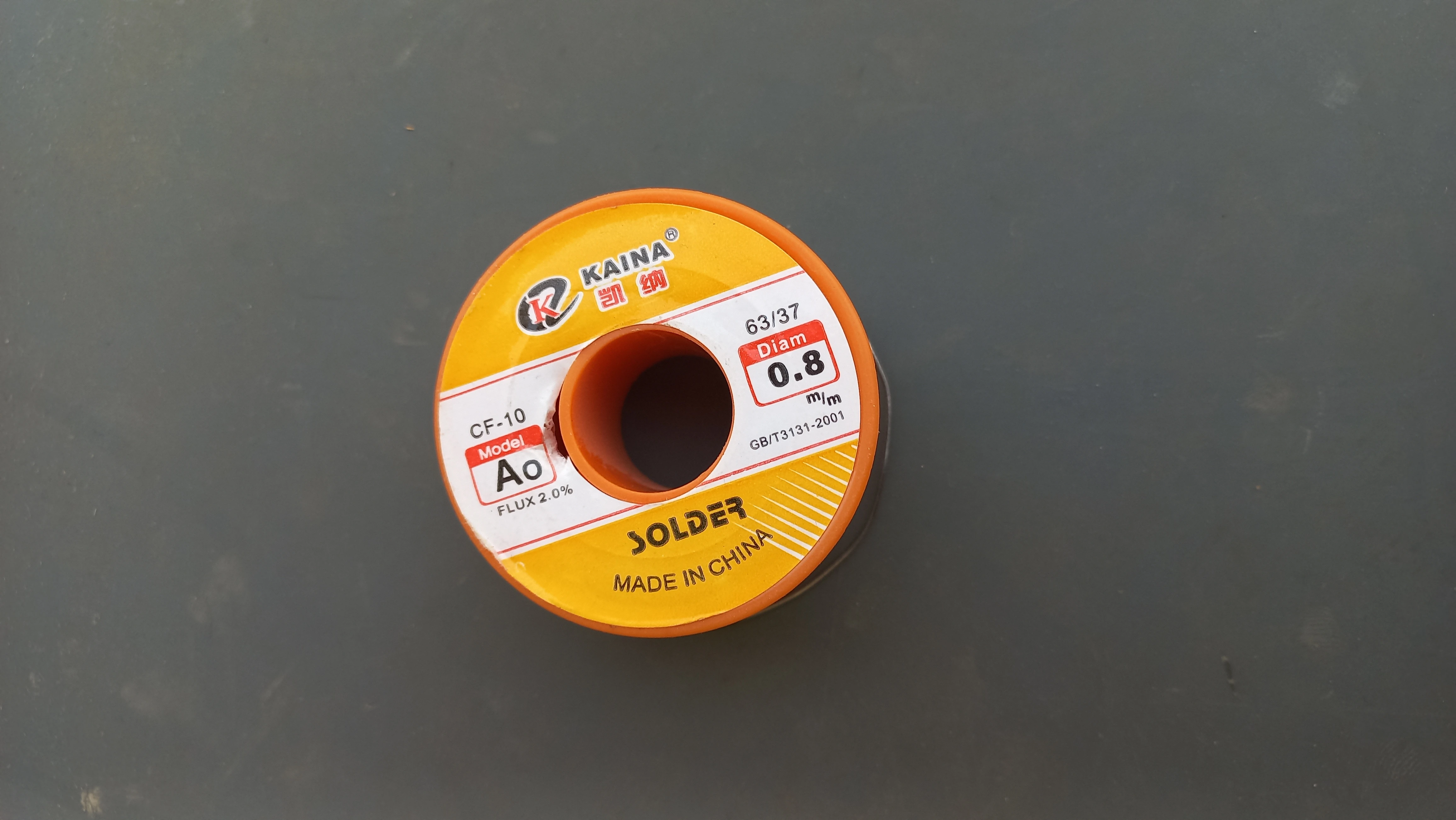
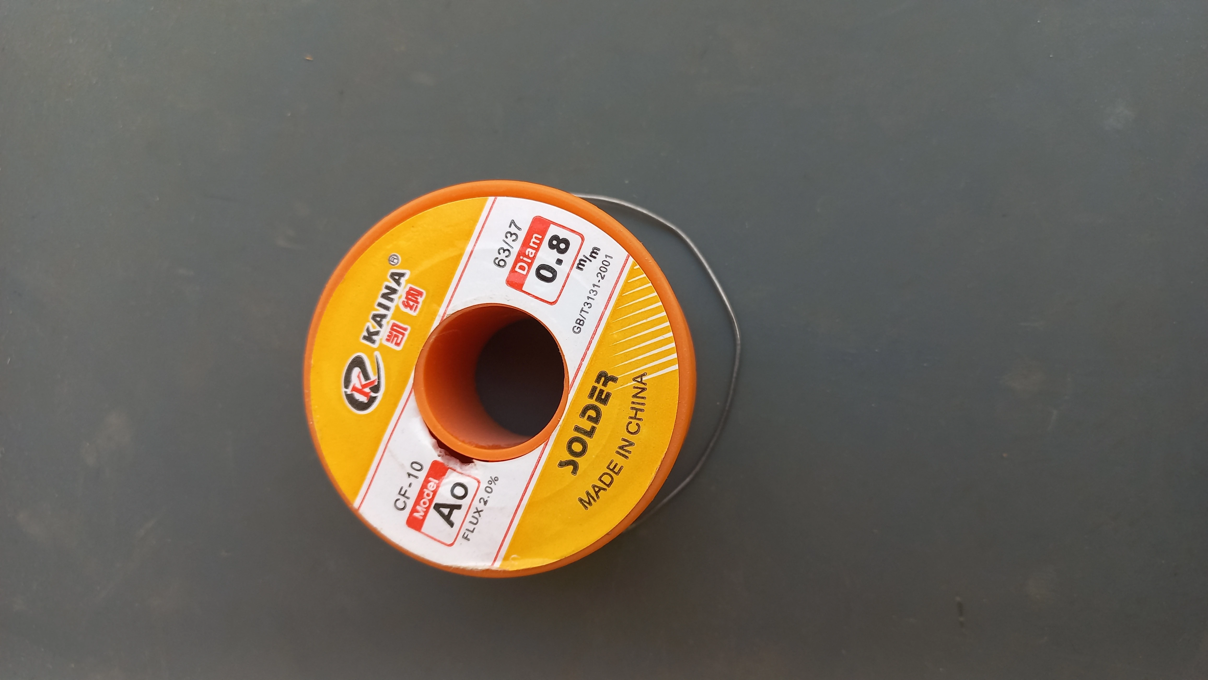
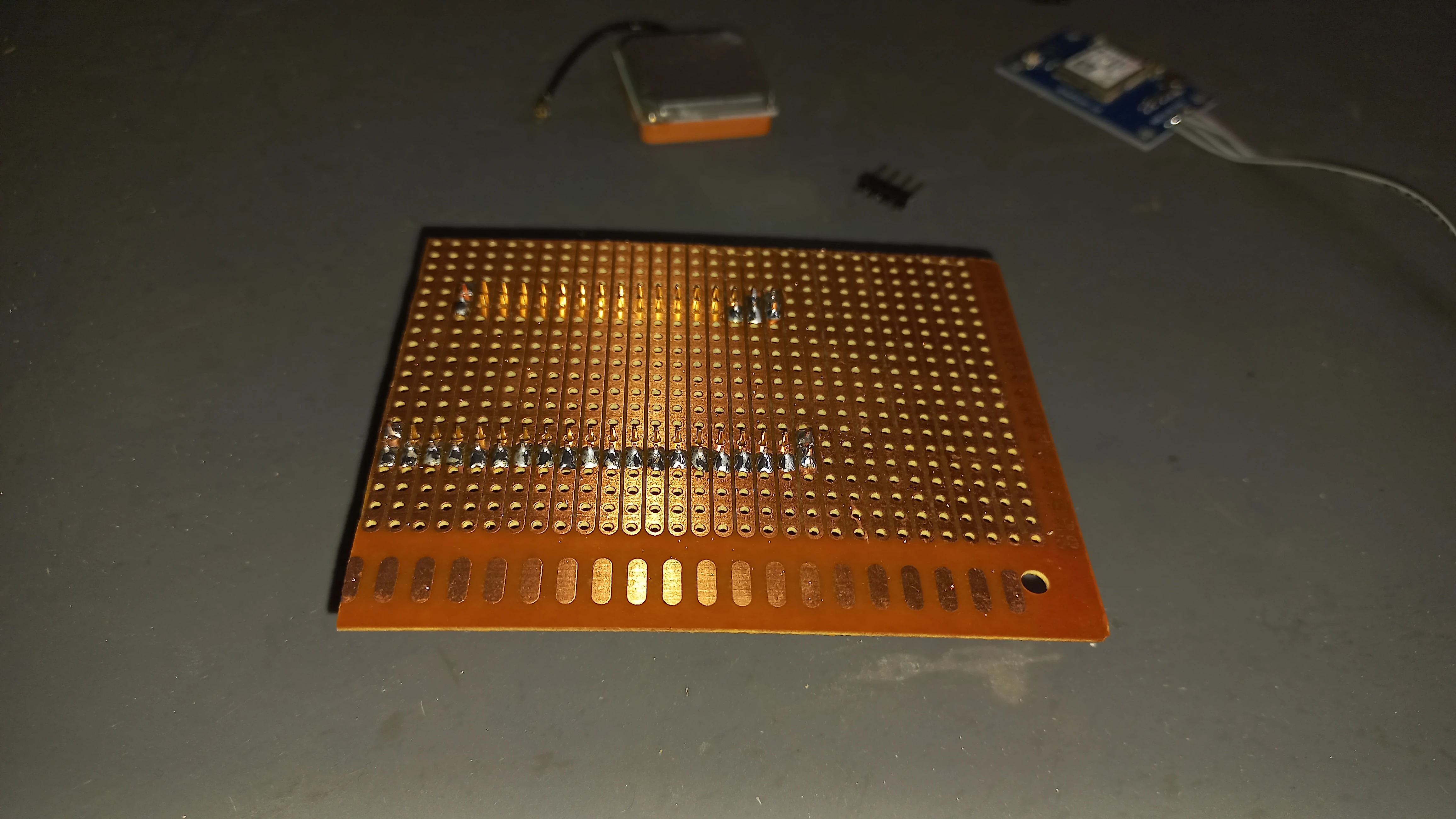
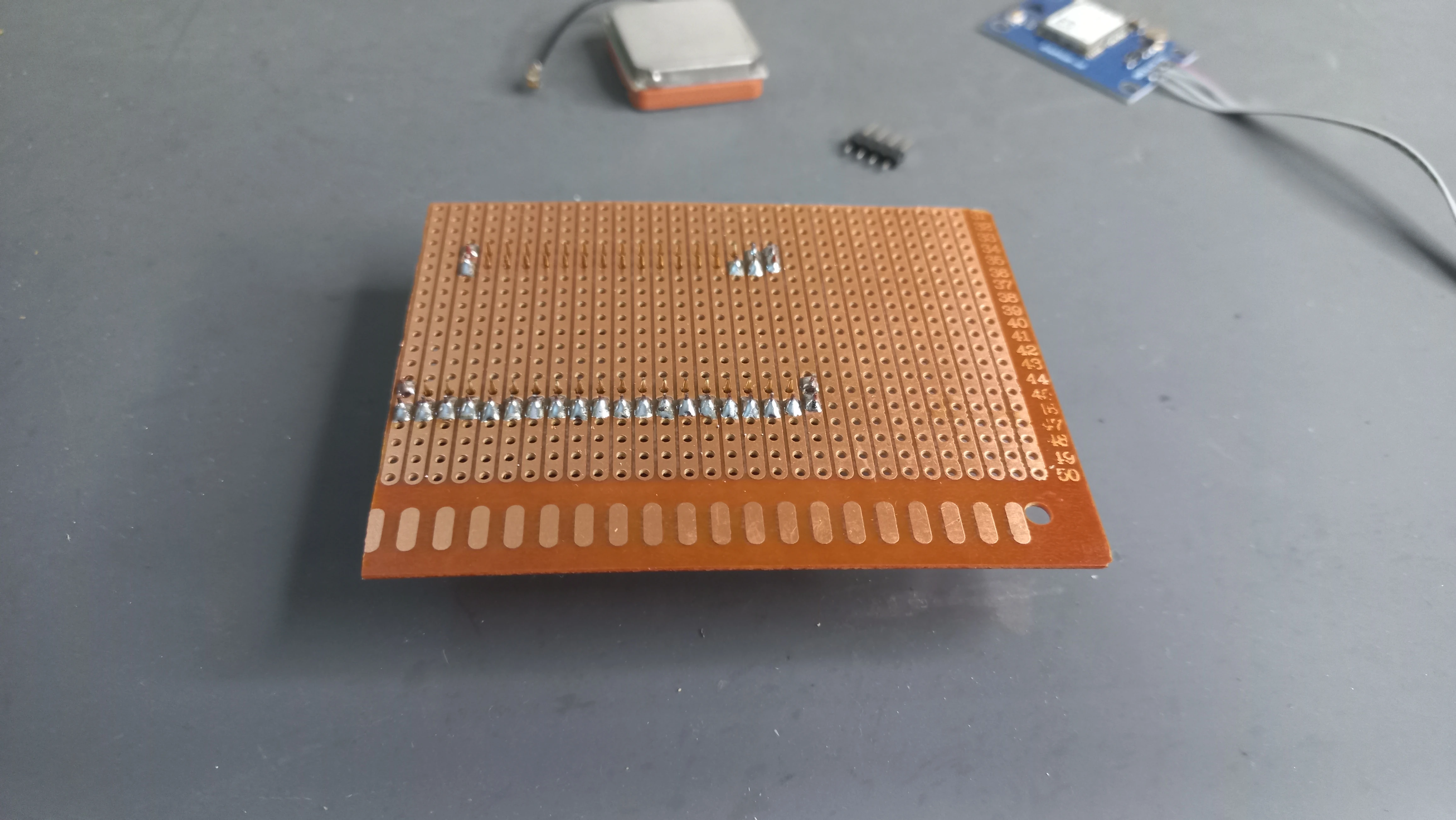
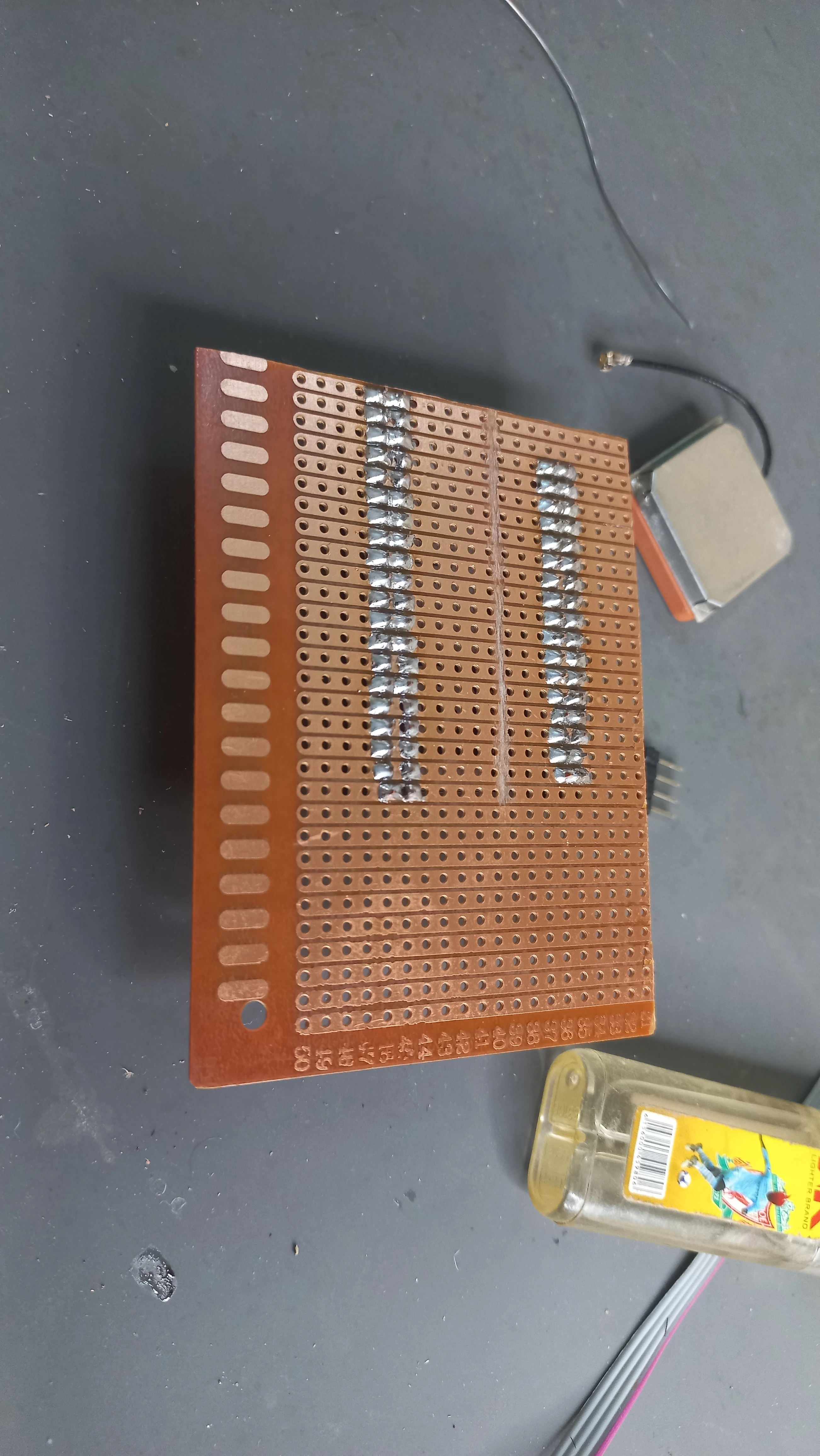
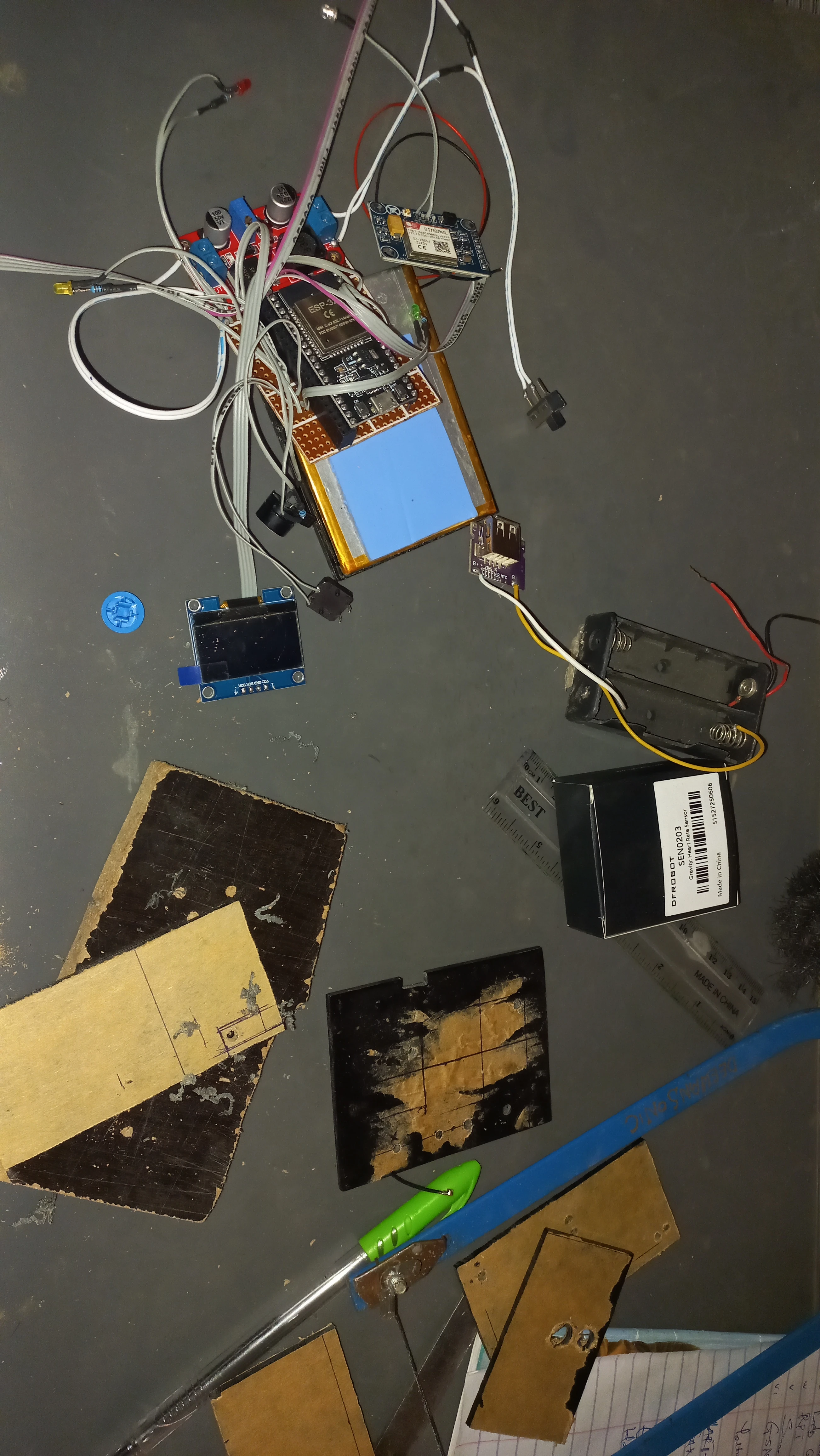
| Prototyping PCB | 9 cm × 15 cm copper perfboard | Permanent soldered integration of all components |
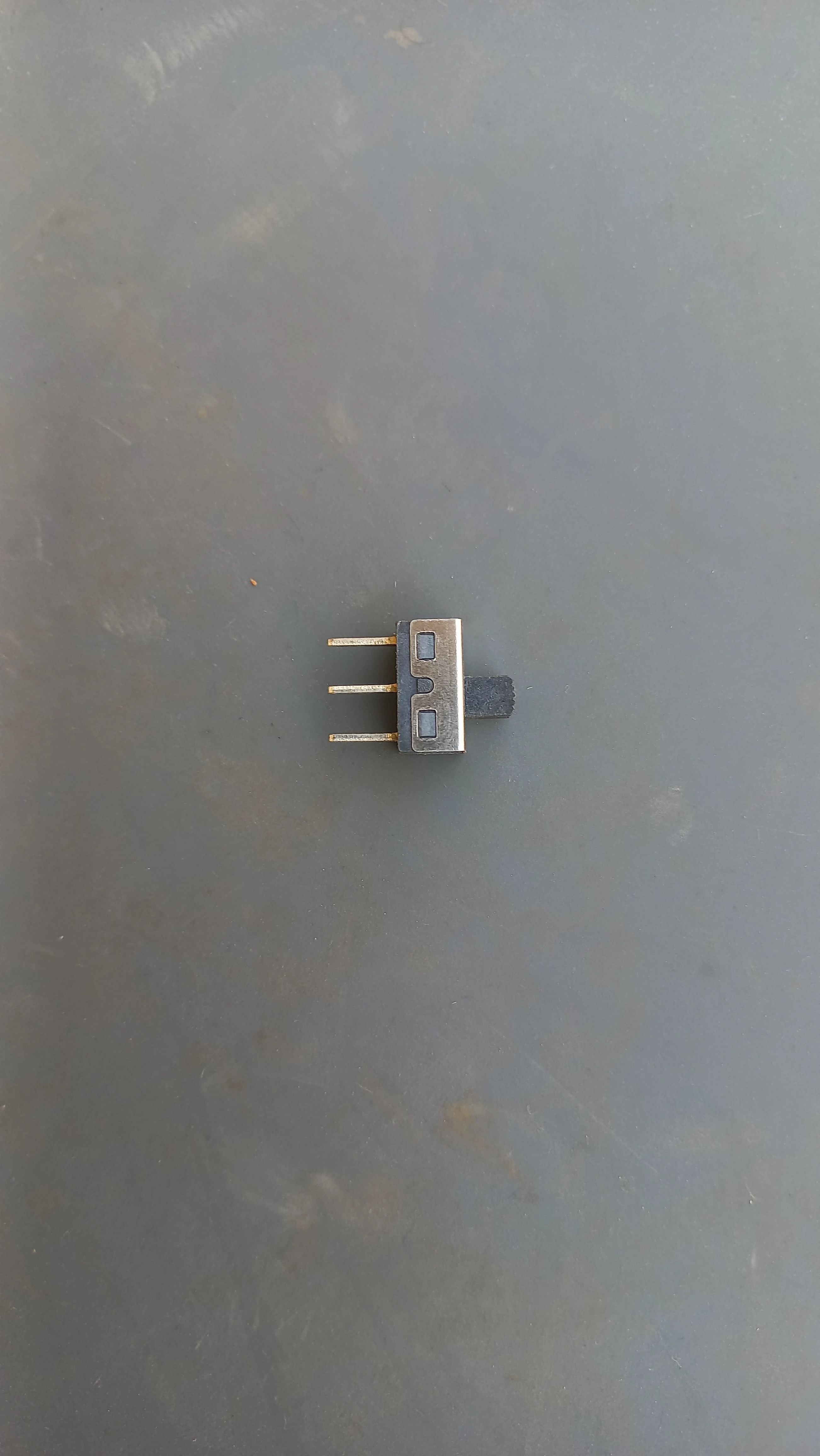
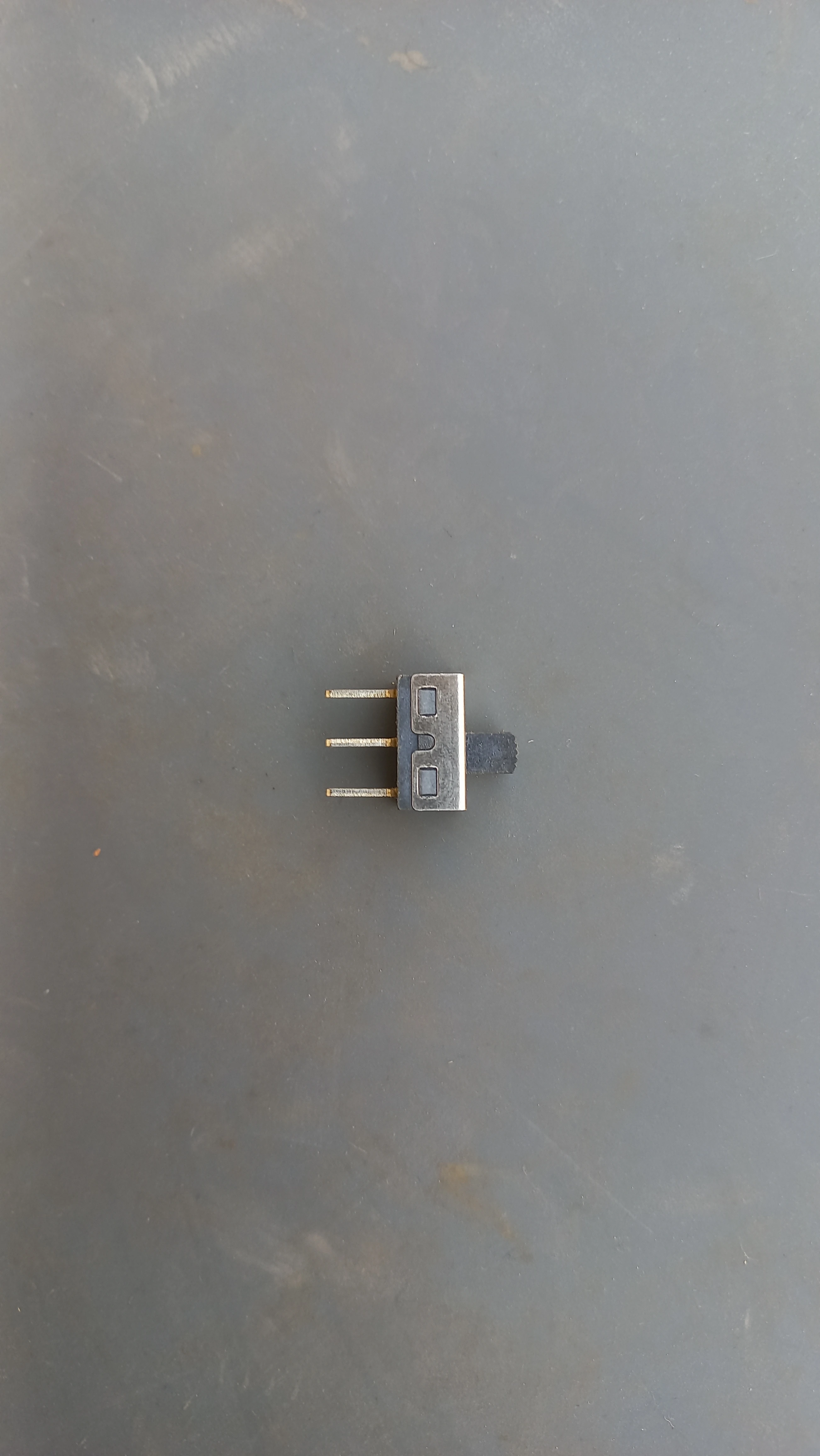
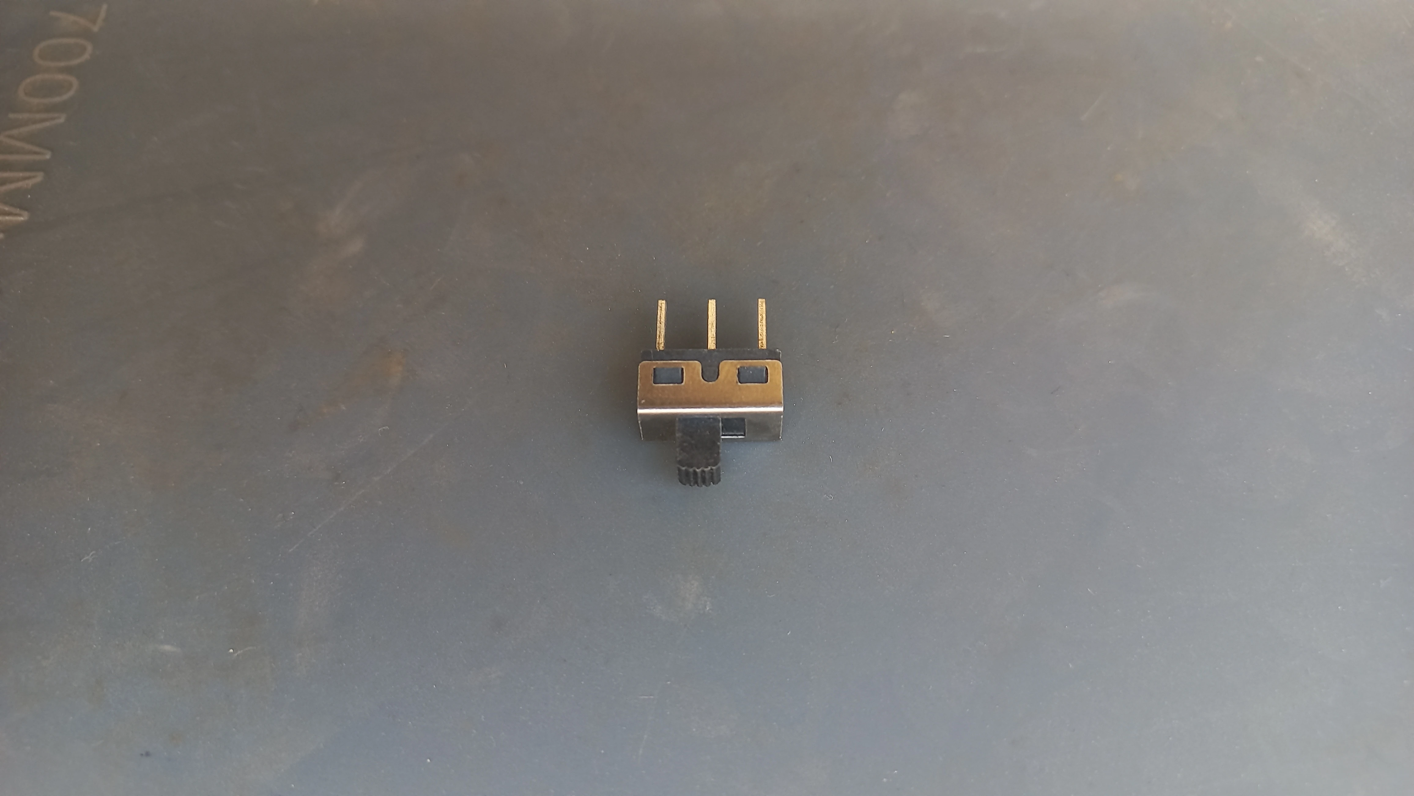
| Power Switch | 3-pin slide switch | Clean power on/off; wired in series with LiPo positive |
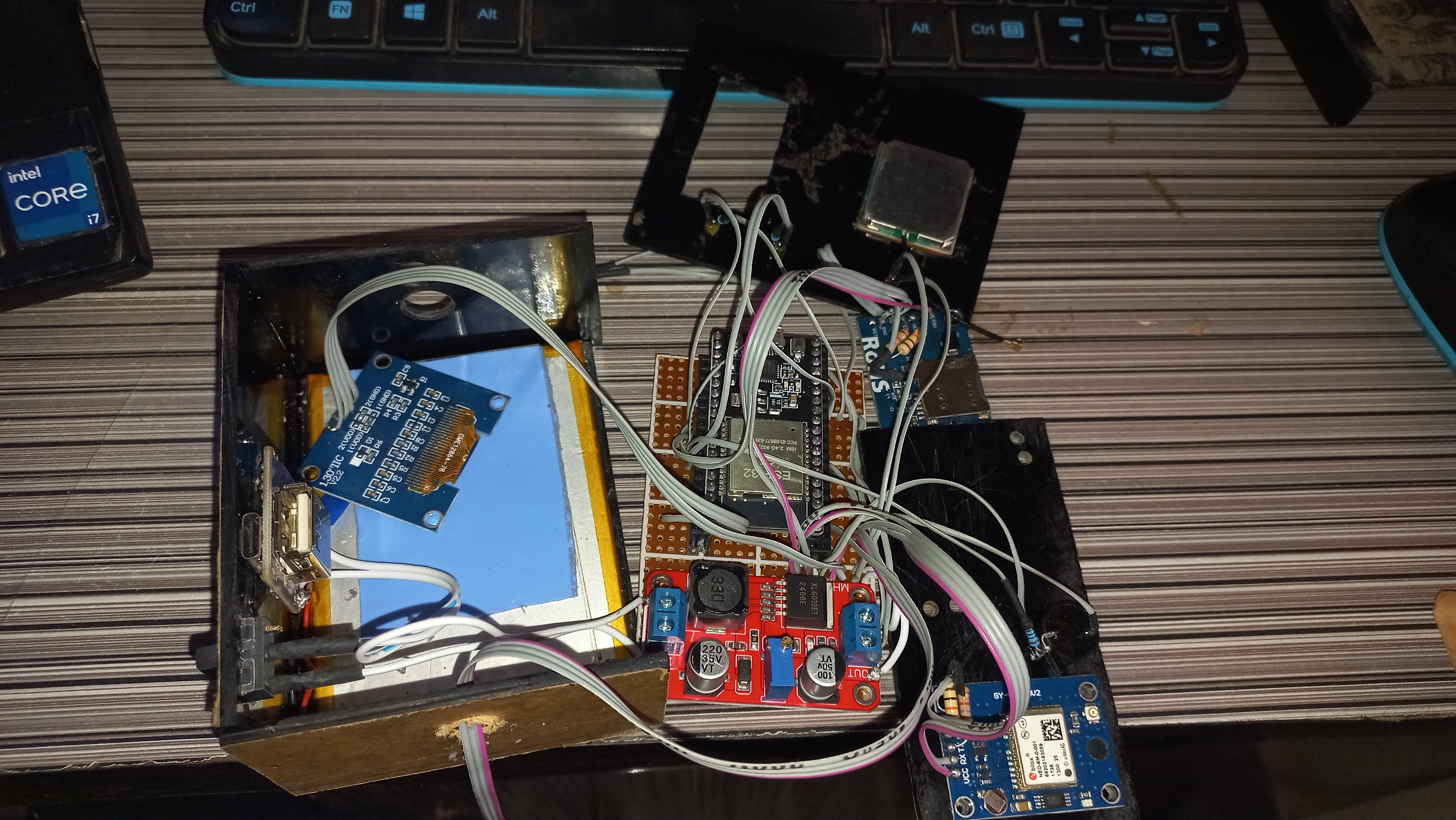
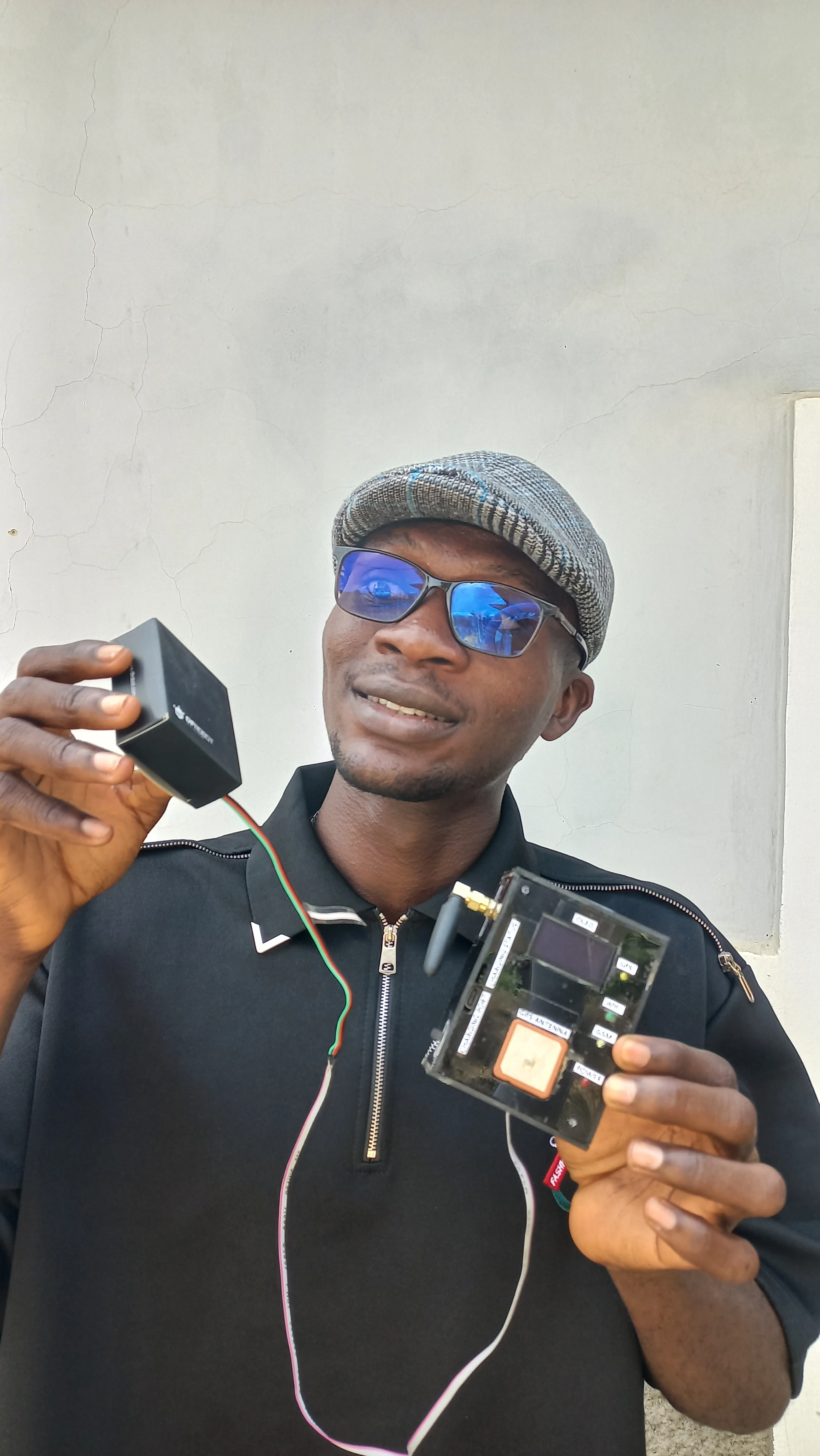
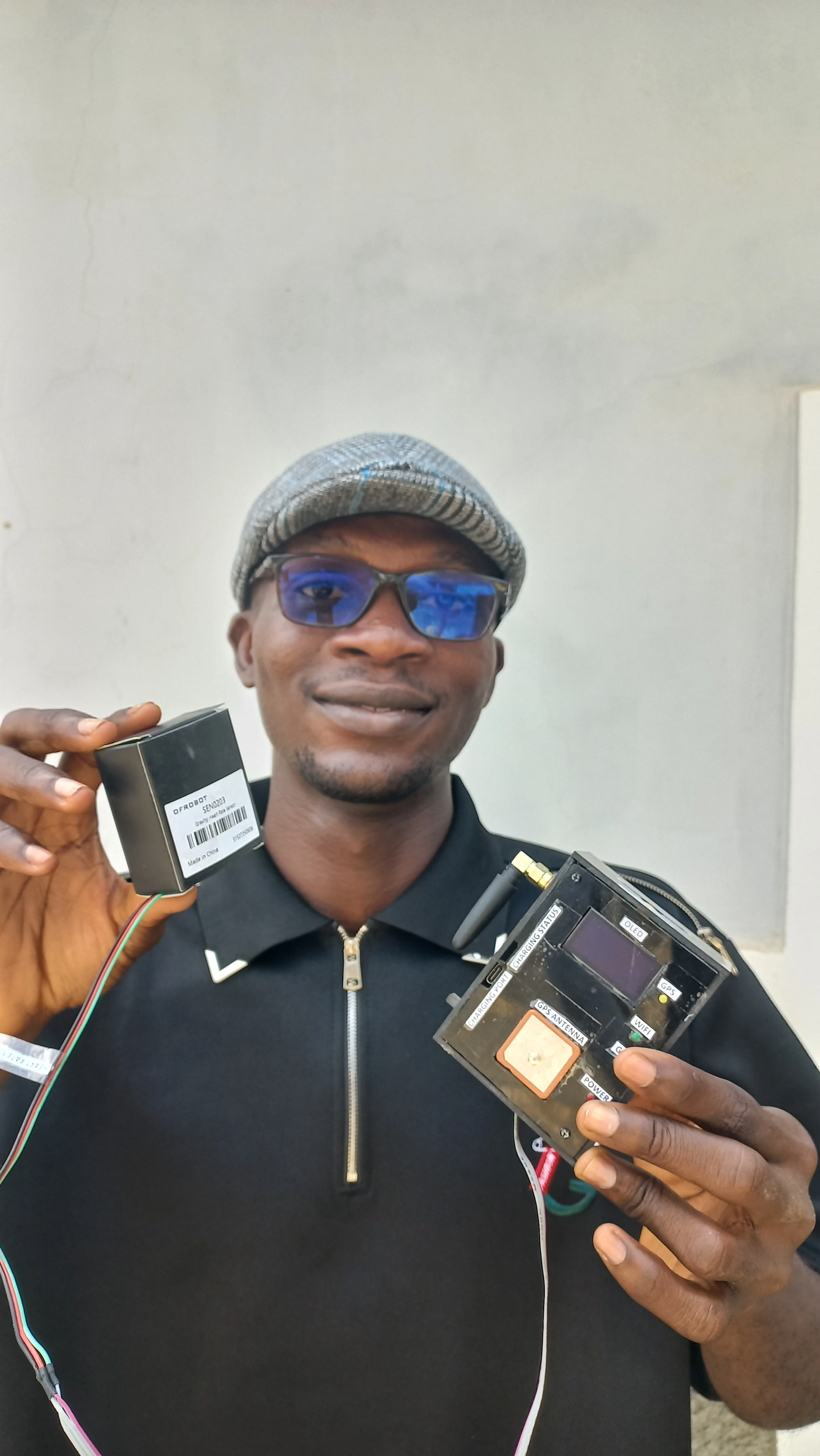
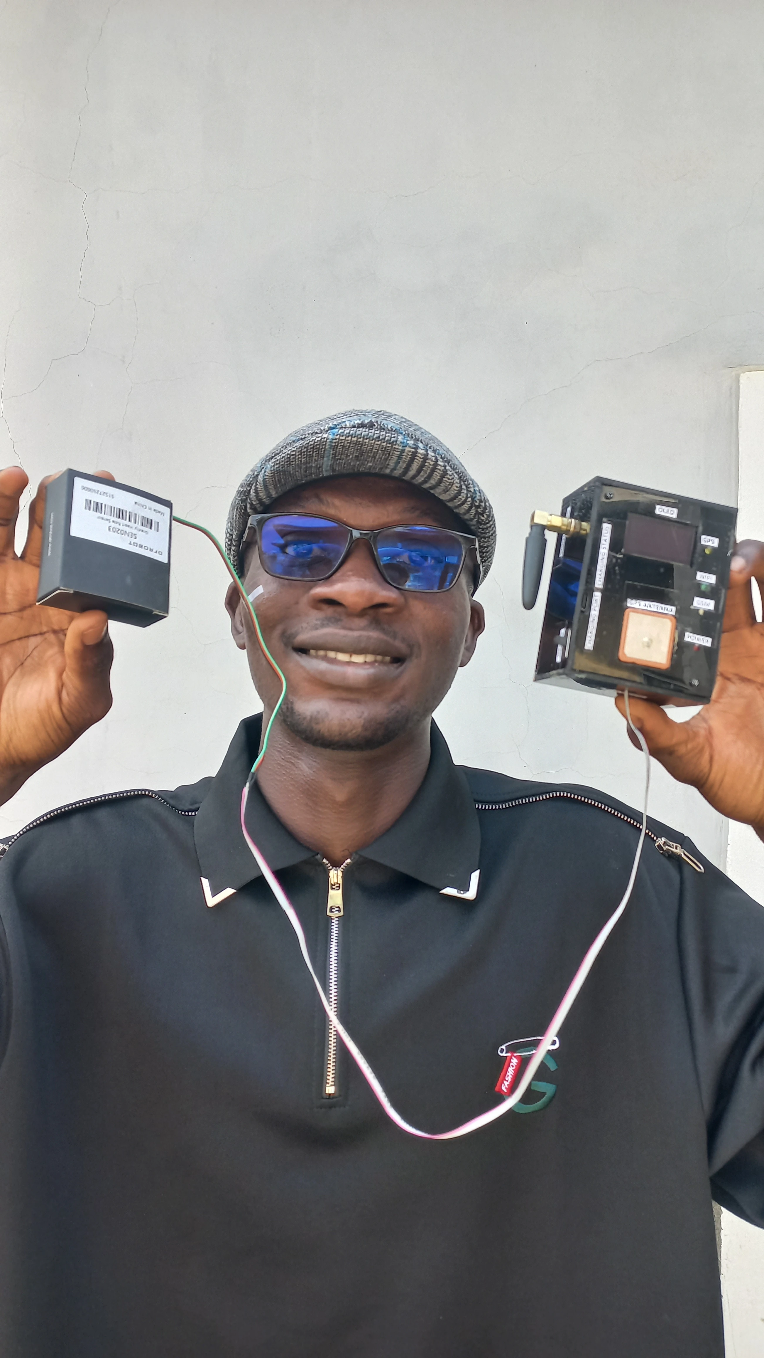
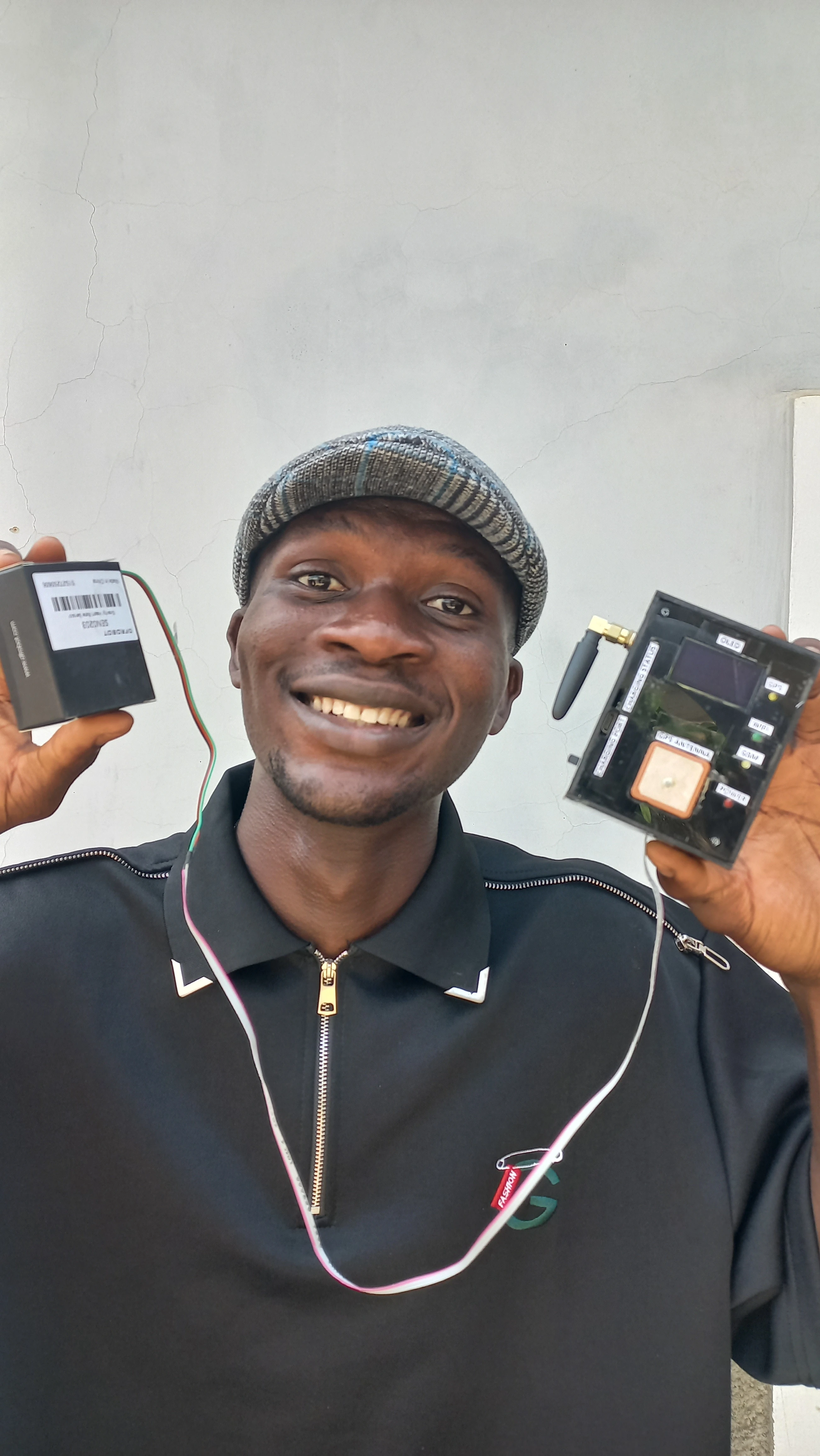
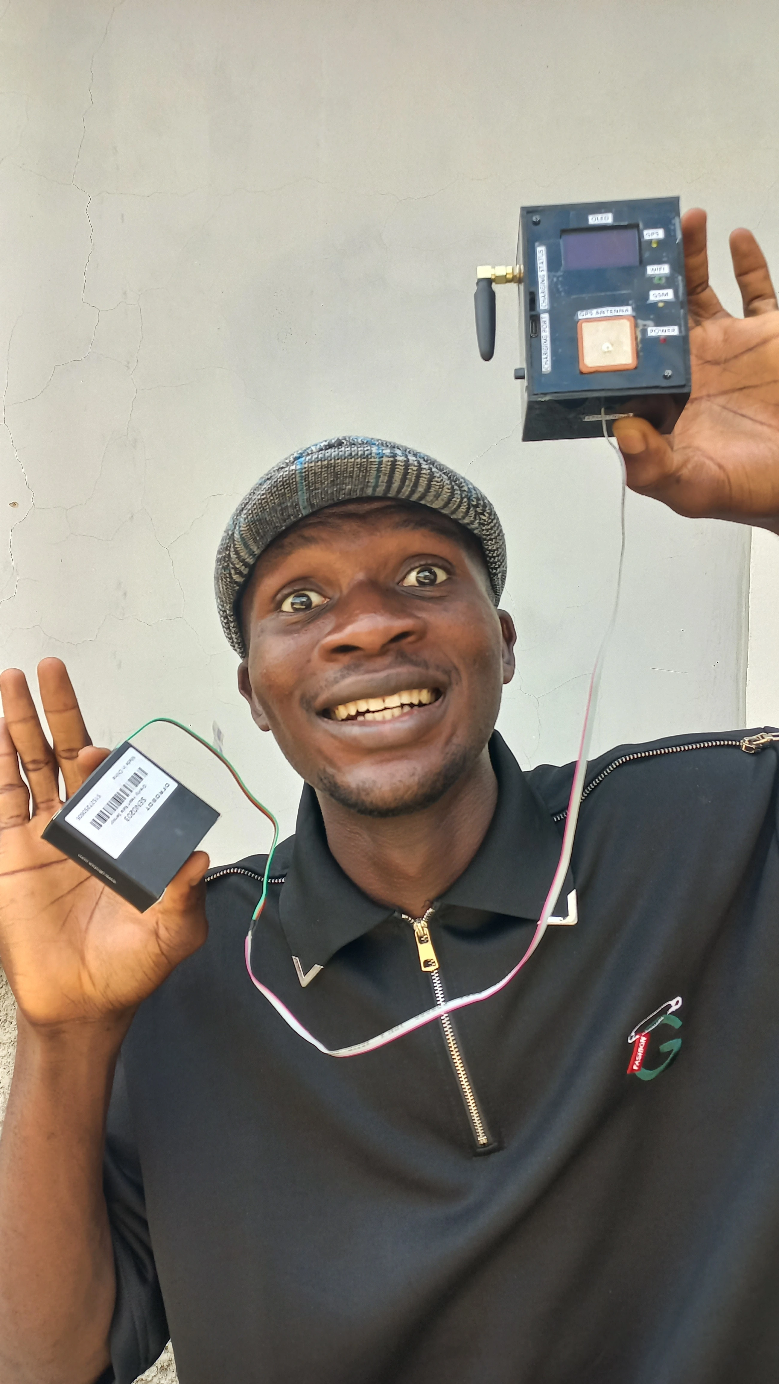
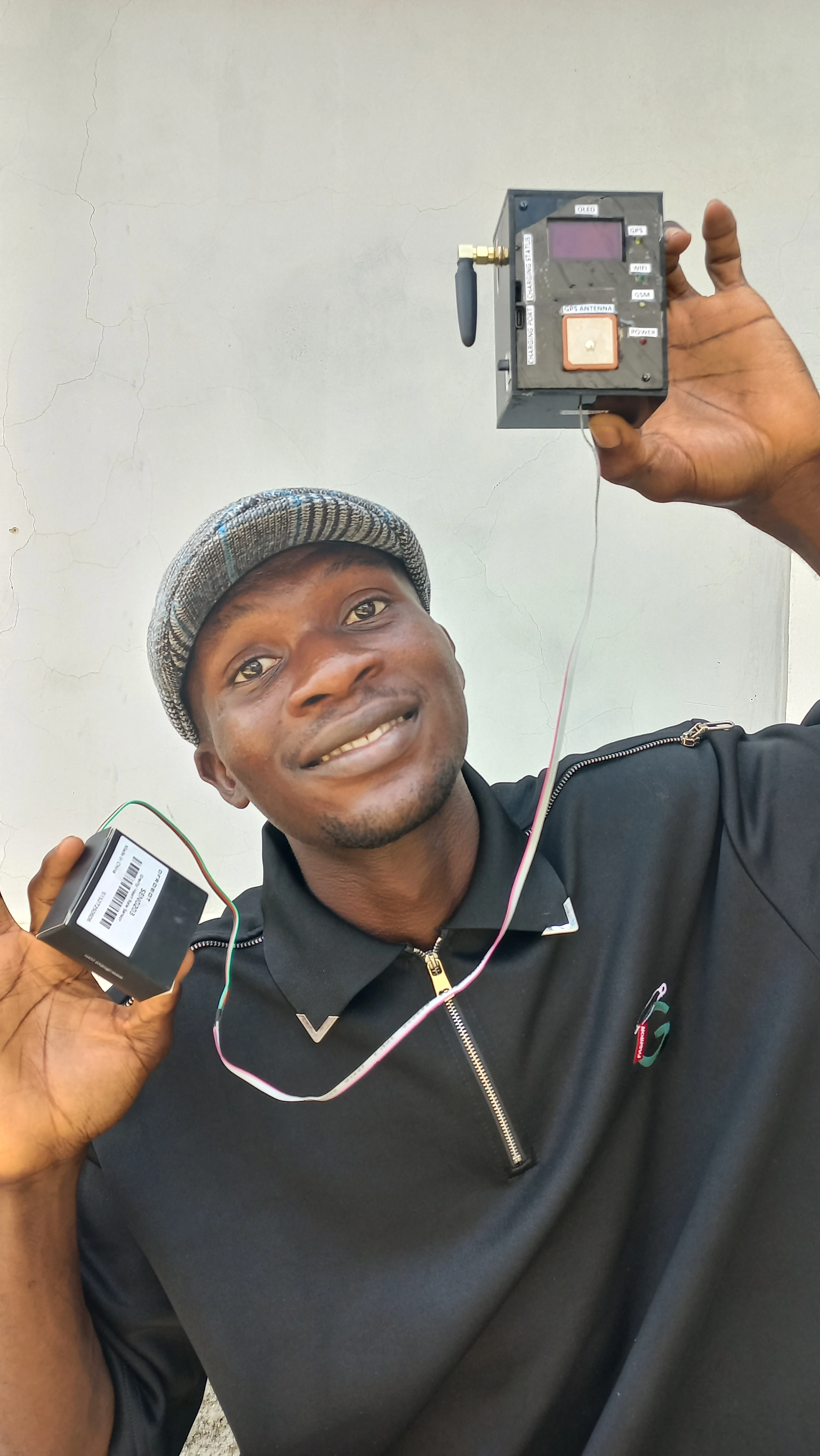
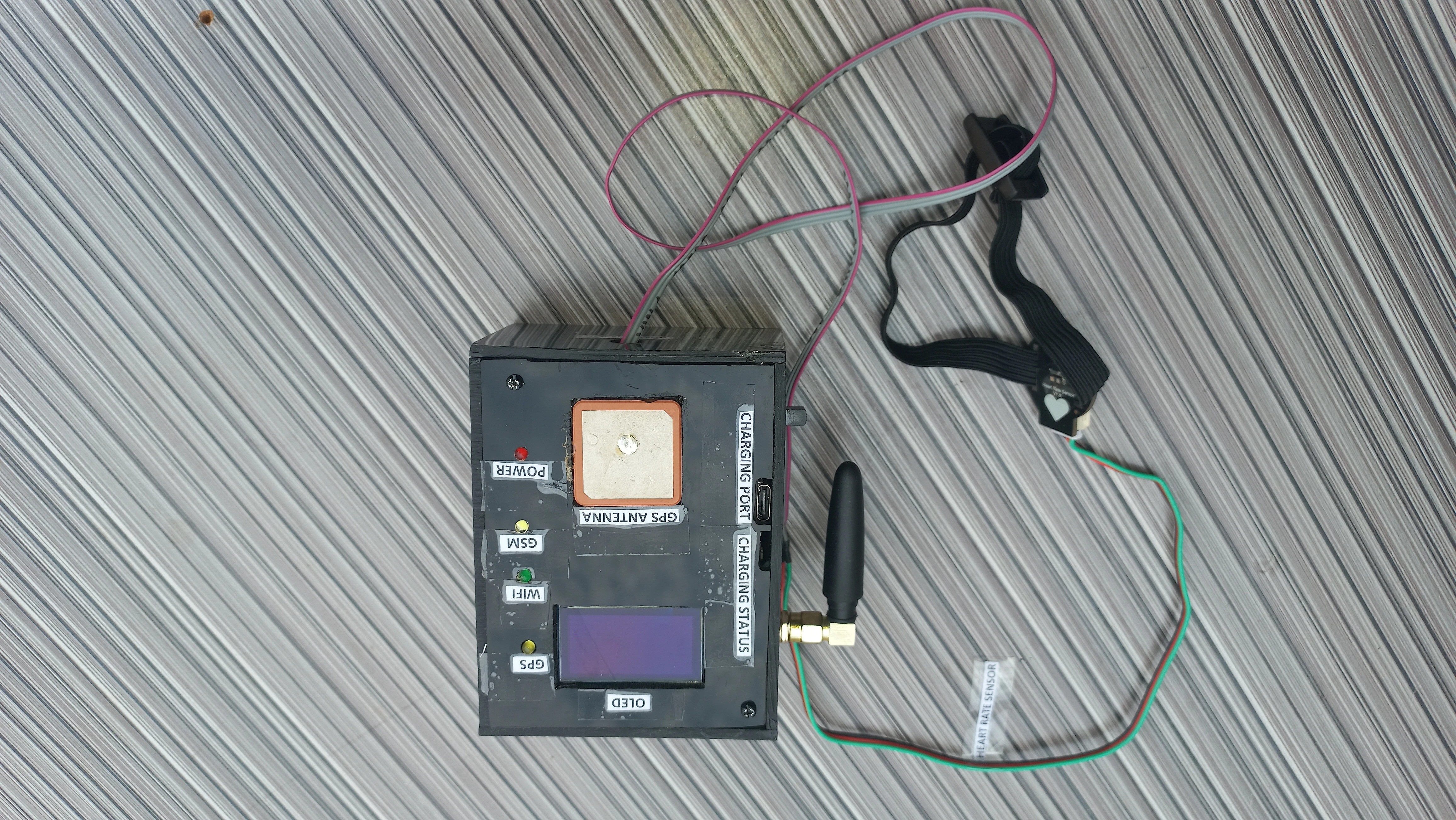
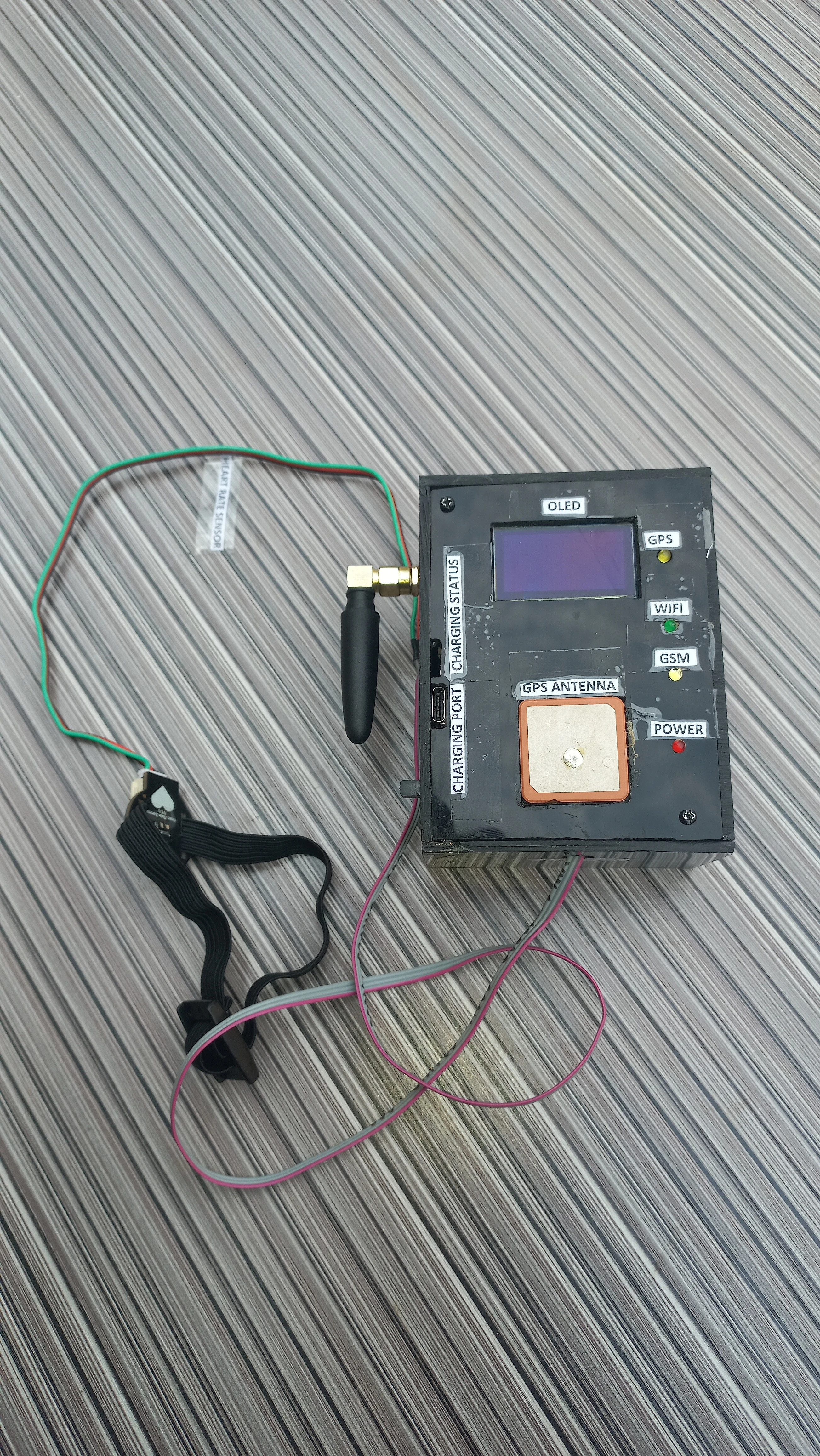
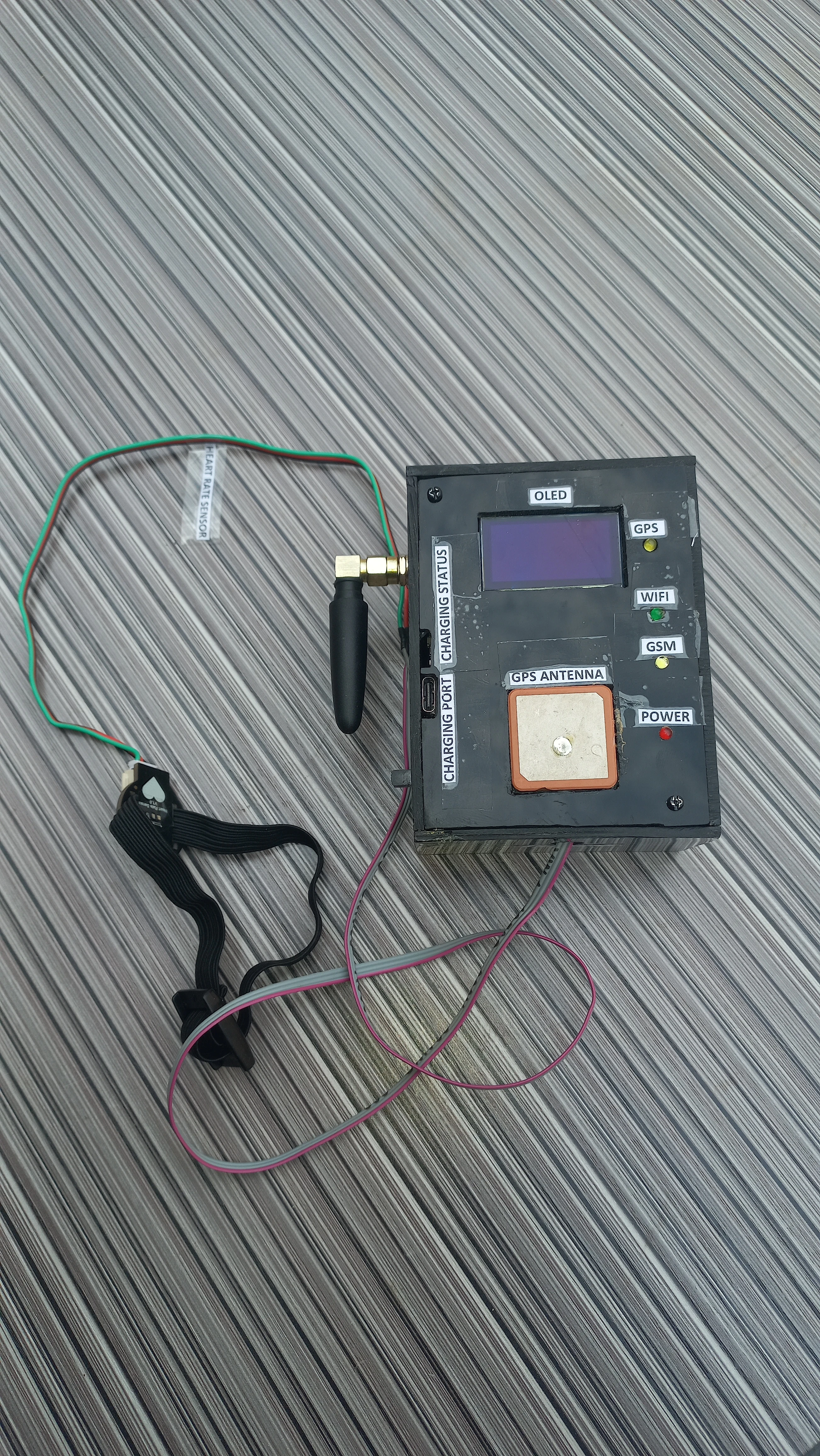
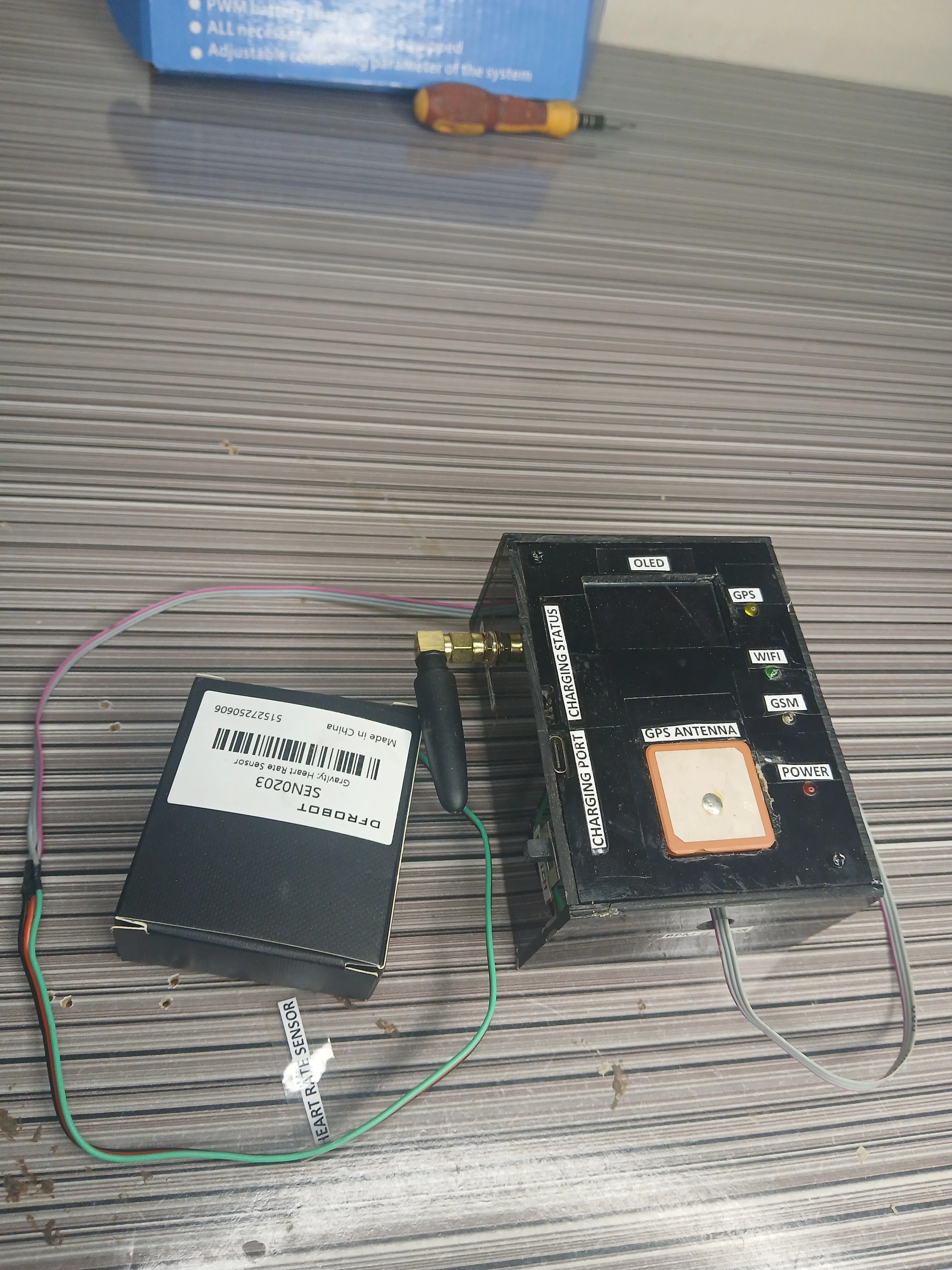
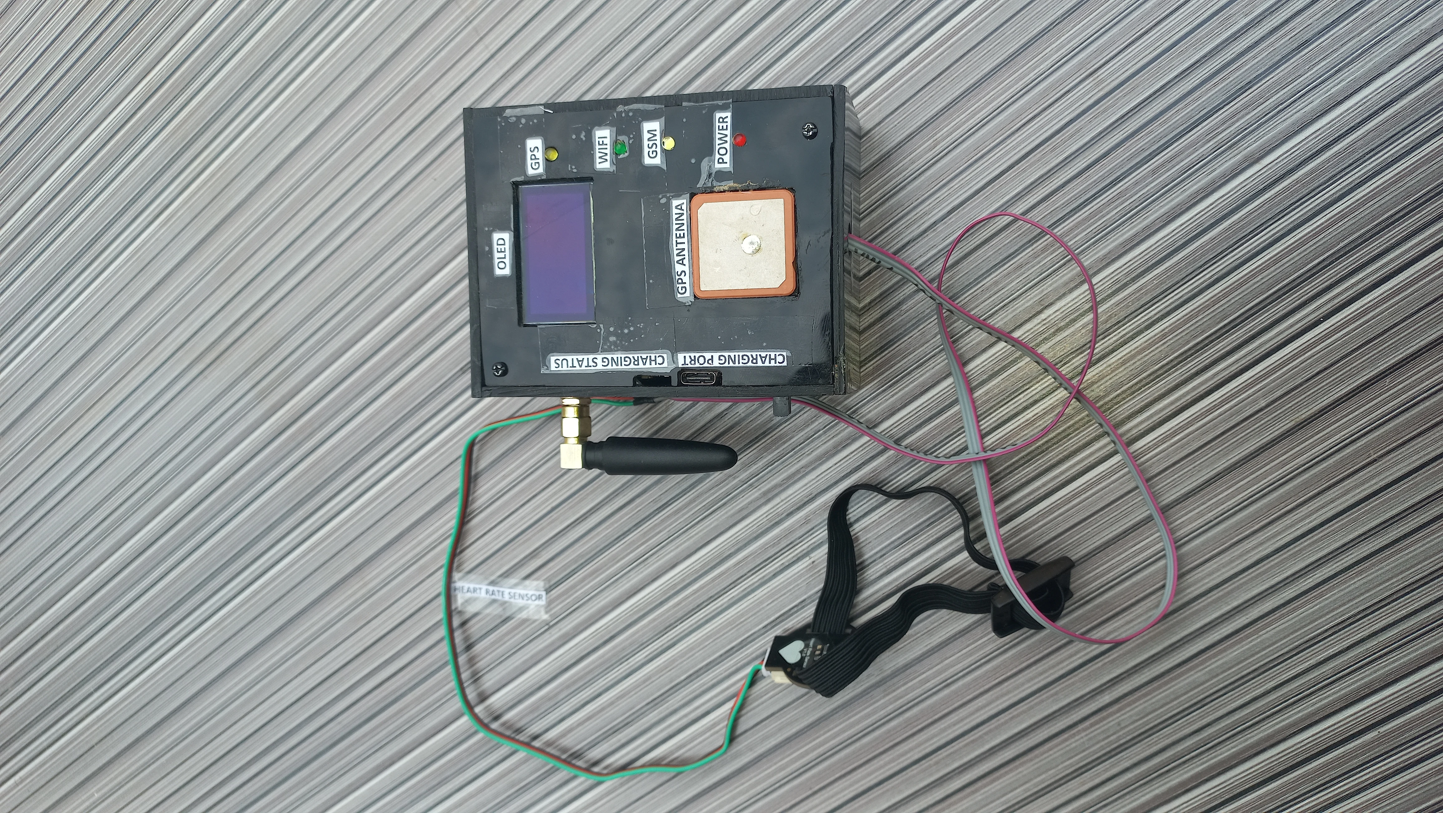
| Enclosure | Black electronic project box | Houses perfboard, battery, OLED, antennas with labelled cutouts |
| ESP32 GPIO | Signal | Peripheral | Notes |
|---|---|---|---|
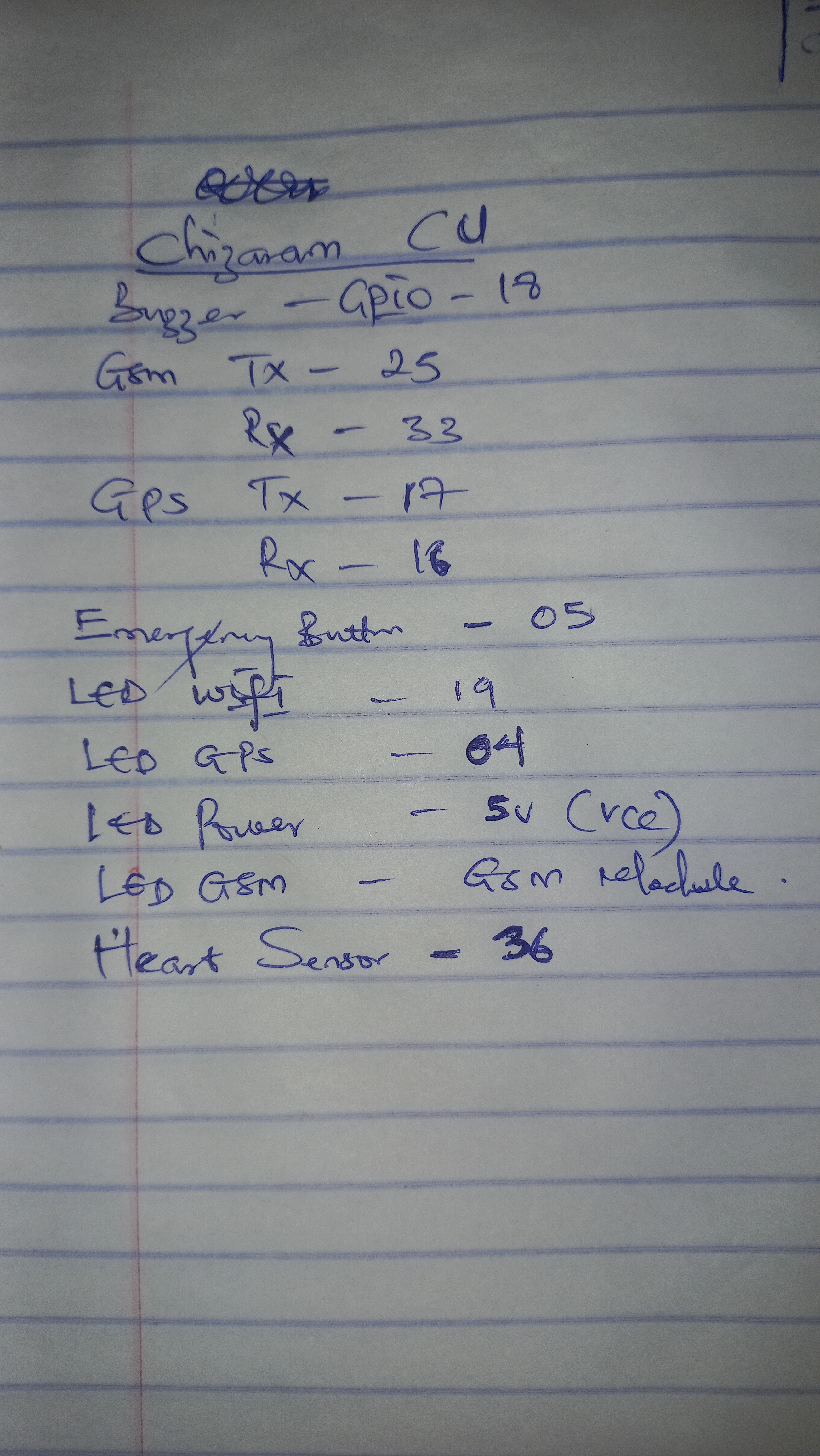
| GPIO 16 | GPS_RX | NEO-6M GPS TX | UART2 receive |
| GPIO 17 | GPS_TX | NEO-6M GPS RX | UART2 transmit |
| GPIO 25 | GSM_RX | SIM800L TX | UART1 receive (remapped to avoid ESP32 flash conflict) |
| GPIO 33 | GSM_TX | SIM800L RX | UART1 transmit (remapped to avoid ESP32 flash conflict) |
| GPIO 36 | PULSE_INPUT | DFRobot PPG sensor output | Input-only ADC pin; 10-bit resolution; threshold = 550 |
| GPIO 2 | PULSE_BLINK | Onboard LED | Blinks on each detected heartbeat |
| GPIO 5 | BUTTON_PIN | Panic button | INPUT_PULLUP; active LOW; 50 ms debounce |
| GPIO 18 | BUZZER_PIN | Active buzzer via BC547 | HIGH = beep; driven via NPN transistor |
| GPIO 19 | WIFI_LED_PIN | Green status LED | HIGH when WiFi.status() == WL_CONNECTED |
| GPIO 4 | GPS_LED_PIN | Yellow status LED | HIGH when GPS location is valid |
| GPIO 21 / 22 | SDA / SCL | SH1106 OLED (I2C) | Default ESP32 I2C bus via Wire.begin() |
The PPG heart rate subsystem uses a 3-state machine to eliminate the noisy, erratic readings that occur immediately after the user places their finger on the sensor. Only after 18 seconds of confirmed successive beats does the firmware promote to active monitoring mode.
abnormalBeatCount. Five consecutive abnormal beats triggers triggerDanger(). A normal beat resets the counter to 0.
If 7 seconds pass without any beat detection in any non-IDLE state, the machine resets to HR_IDLE. This handles the user removing their finger mid-session without a firmware restart.
// Heart Rate State Machine (inside loop())
if (pulseSensor.sawStartOfBeat()) {
    currentBPM = pulseSensor.getBeatsPerMinute();
    lastBeatTime = currentMillis;

    if (hrState == HR_IDLE) {
        hrState = HR_STABILIZING;
        stabilizeStartTime = currentMillis;
    }
    else if (hrState == HR_STABILIZING) {
        if (currentMillis - stabilizeStartTime > STABILIZE_DURATION) {  // 18 s
            hrState = HR_MONITORING;
            abnormalBeatCount = 0;
        }
    }
    else if (hrState == HR_MONITORING) {
        if (!alertActive) {
            if (currentBPM < 50 || currentBPM > 120) {
                abnormalBeatCount++;
                if (abnormalBeatCount >= 5) {
                    triggerDanger("Auto-Alert: Abnormal Heart Rate (" + String(currentBPM) + " BPM)!");
                    abnormalBeatCount = 0;
                }
            } else {
                abnormalBeatCount = 0;  // normal beat resets counter
            }
        }
    }
}

// Finger-removed timeout: reset to IDLE after 7 s with no beat
if (hrState != HR_IDLE && (currentMillis - lastBeatTime > FINGER_REMOVED_TIMEOUT)) {
    hrState = HR_IDLE;
    currentBPM = 0;
    abnormalBeatCount = 0;
}
Both trigger paths converge on triggerDanger(cause), which sets alertActive = true, fetches the current GPS location and NTP timestamp, builds the SMS body, and dispatches via SIM800L. The 2-second long press calls triggerSafe(), which mirrors the same pattern but clears alertActive and sends a "I am safe now" SMS.
void triggerDanger(String cause) {
    alertActive = true;
    currentTimestamp = getFormattedTime();

    String smsMsg = cause + "\n";
    if (gpsValid) {
        smsMsg += "Please help! Location: " + locationURL + "\n";
    } else {
        smsMsg += "Please help! GPS unavailable.\n";
    }
    smsMsg += "Time: " + currentTimestamp;

    if (WiFi.status() == WL_CONNECTED) {
        Firebase.setString(fbdo, "/Alert_Message",
            cause + " Location: " + locationURL + " | " + currentTimestamp);
    }
    sendSMS(recipientNumber, smsMsg);
}

void triggerSafe() {
    alertActive = false;
    digitalWrite(BUZZER_PIN, LOW);
    currentTimestamp = getFormattedTime();

    String smsMsg = "I am safe now. False alarm or danger passed.\n";
    if (gpsValid) smsMsg += "Current Location: " + locationURL + "\n";
    smsMsg += "Time: " + currentTimestamp;

    if (WiFi.status() == WL_CONNECTED) {
        Firebase.setString(fbdo, "/Alert_Message",
            "Safe Mode Activated. | " + currentTimestamp);
    }
    sendSMS(recipientNumber, smsMsg);
}
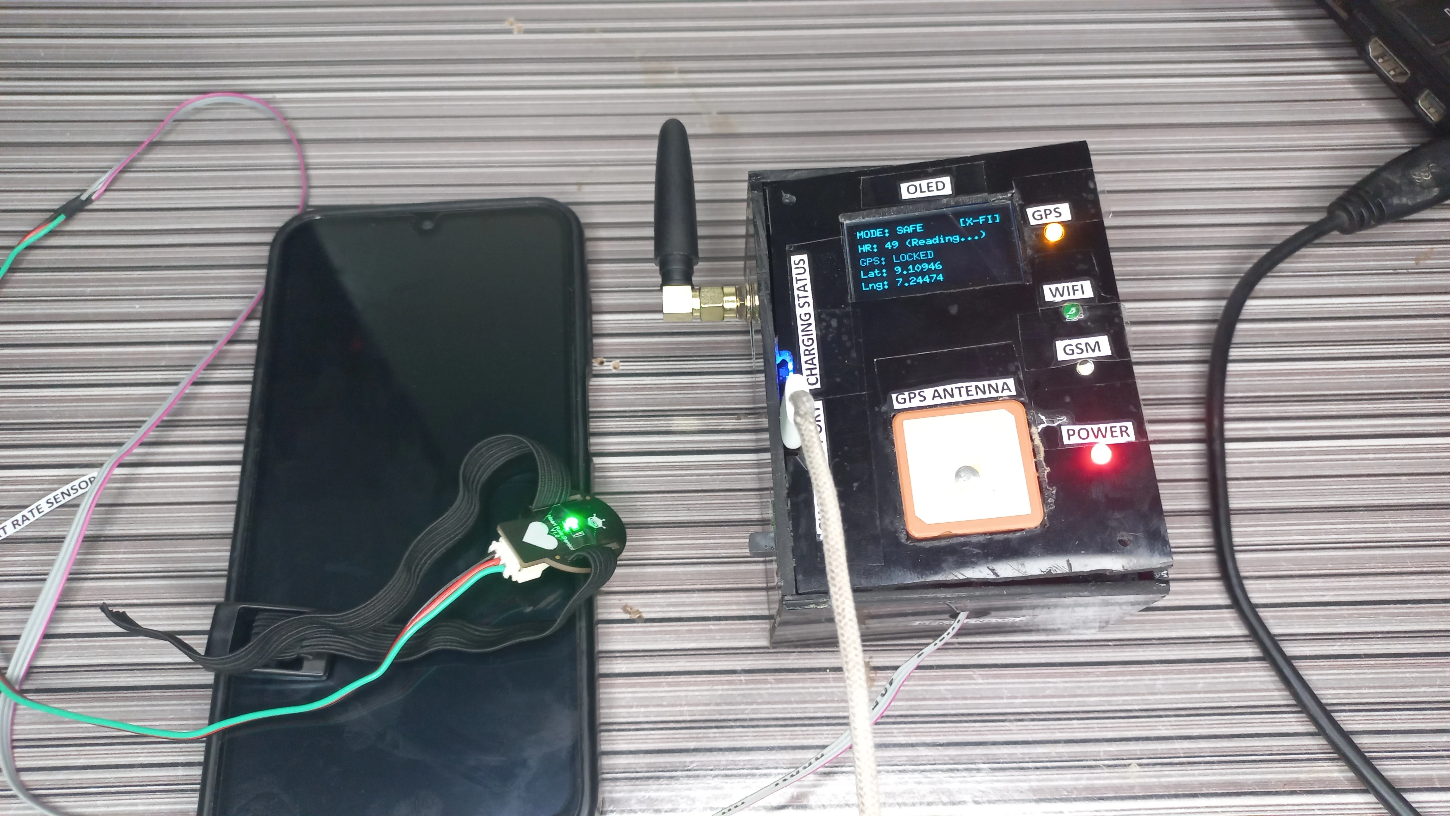
The SH1106 1.3” OLED runs in U8g2 page-buffer mode (U8G2_SH1106_128X64_NONAME_1_HW_I2C) and refreshes every 1 second. Page-buffer mode renders one horizontal band at a time, requiring less RAM than the full-frame buffer while still producing a flicker-free display. The dashboard has two screen modes:
The OLED also shows dedicated boot and SMS-sending screens: on startup it displays the project title and student matriculation number for 3 seconds; while an SMS is being dispatched it shows "SENDING SMS... Please Wait." to inform the user.
void updateOLED() {
    display.firstPage();
    do {
        display.setFont(u8g2_font_6x10_tf);

        // New contact overlay: 3-second non-blocking popup
        if (showNewContactOverlay && (millis() - newContactOverlayTime < 3000)) {
            display.drawStr(10, 15, "NEW CONTACT SYNCED");
            display.drawHLine(0, 22, 128);
            display.drawStr(10, 40, displayContactNumber.c_str());
            display.drawStr(10, 55, "System Updated.");
        }
        else {
            showNewContactOverlay = false;

            // Wi-Fi status (top-right)
            display.drawStr(92, 10, (WiFi.status() == WL_CONNECTED) ? "[WIFI]" : "[X-FI]");

            // Alert mode (top-left)
            display.drawStr(0, 10, alertActive ? "MODE: DANGER!" : "MODE: SAFE");

            // Heart rate row
            String hrStr = "HR: ";
            if      (hrState == HR_IDLE)        hrStr += "-- (Place Finger)";
            else if (hrState == HR_STABILIZING) hrStr += String(currentBPM) + " (Reading...)";
            else                                hrStr += String(currentBPM) + " BPM (Active)";
            display.drawStr(0, 24, hrStr.c_str());

            // GPS rows
            if (gpsValid) {
                display.drawStr(0, 38, "GPS: LOCKED");
                display.drawStr(0, 50, ("Lat: " + String(latitude, 5)).c_str());
                display.drawStr(0, 62, ("Lng: " + String(longitude, 5)).c_str());
            } else {
                display.drawStr(0, 38, "GPS: SEARCHING...");
                display.drawStr(0, 50, "Lat: --");
                display.drawStr(0, 62, "Lng: --");
            }
        }
    } while (display.nextPage());
}The device connects to Firebase Realtime Database using the FirebaseESP32 library with a legacy token. Three Firebase paths are used:
/Telemetry: a JSON object pushed every 6 seconds containing BPM, Status ("SAFE" or "DANGER"), Latitude, Longitude, and LocationURL/Phone_Number: a string read every 10 seconds; if a new number is detected it replaces recipientNumber in RAM and triggers the OLED popup overlay/Alert_Message: a string written immediately on each danger or safe event with the cause, location URL, and NTP timestamp
The NTP client syncs to pool.ntp.org with a UTC+1 offset (3600 seconds) for Nigeria local time. Timestamps are formatted as DD/MM/YYYY HH:MM:SS using localtime() and snprintf().
void sendDataToFirebase() {
    FirebaseJson telemetryData;
    if (gpsValid) {
        telemetryData.set("Latitude",    latitude);
        telemetryData.set("Longitude",   longitude);
        telemetryData.set("LocationURL", locationURL);
    } else {
        telemetryData.set("LocationURL", "Unavailable");
    }
    telemetryData.set("BPM",    currentBPM);
    telemetryData.set("Status", alertActive ? "DANGER" : "SAFE");
    Firebase.set(fbdo, F("/Telemetry"), telemetryData);
}

void readPhoneNumberFromFirebase() {
    if (Firebase.getString(fbdo, "/Phone_Number")) {
        String fetched = fbdo.stringData();
        if (fetched.length() > 5 && recipientNumber != fetched) {
            recipientNumber = fetched;
            // Convert +234 / 234 prefix to local 0-prefix for OLED display
            displayContactNumber = fetched;
            if (displayContactNumber.startsWith("+234"))
                displayContactNumber = "0" + displayContactNumber.substring(4);
            else if (displayContactNumber.startsWith("234"))
                displayContactNumber = "0" + displayContactNumber.substring(3);
            showNewContactOverlay = true;
            newContactOverlayTime = millis();
        }
    }
}

String getFormattedTime() {
    timeClient.update();
    time_t rawTime = timeClient.getEpochTime();
    struct tm *ti = localtime(&rawTime);
    char buffer[25];
    snprintf(buffer, sizeof(buffer), "%02d/%02d/%04d %02d:%02d:%02d",
             ti->tm_mday, ti->tm_mon + 1, ti->tm_year + 1900,
             ti->tm_hour, ti->tm_min, ti->tm_sec);
    return String(buffer);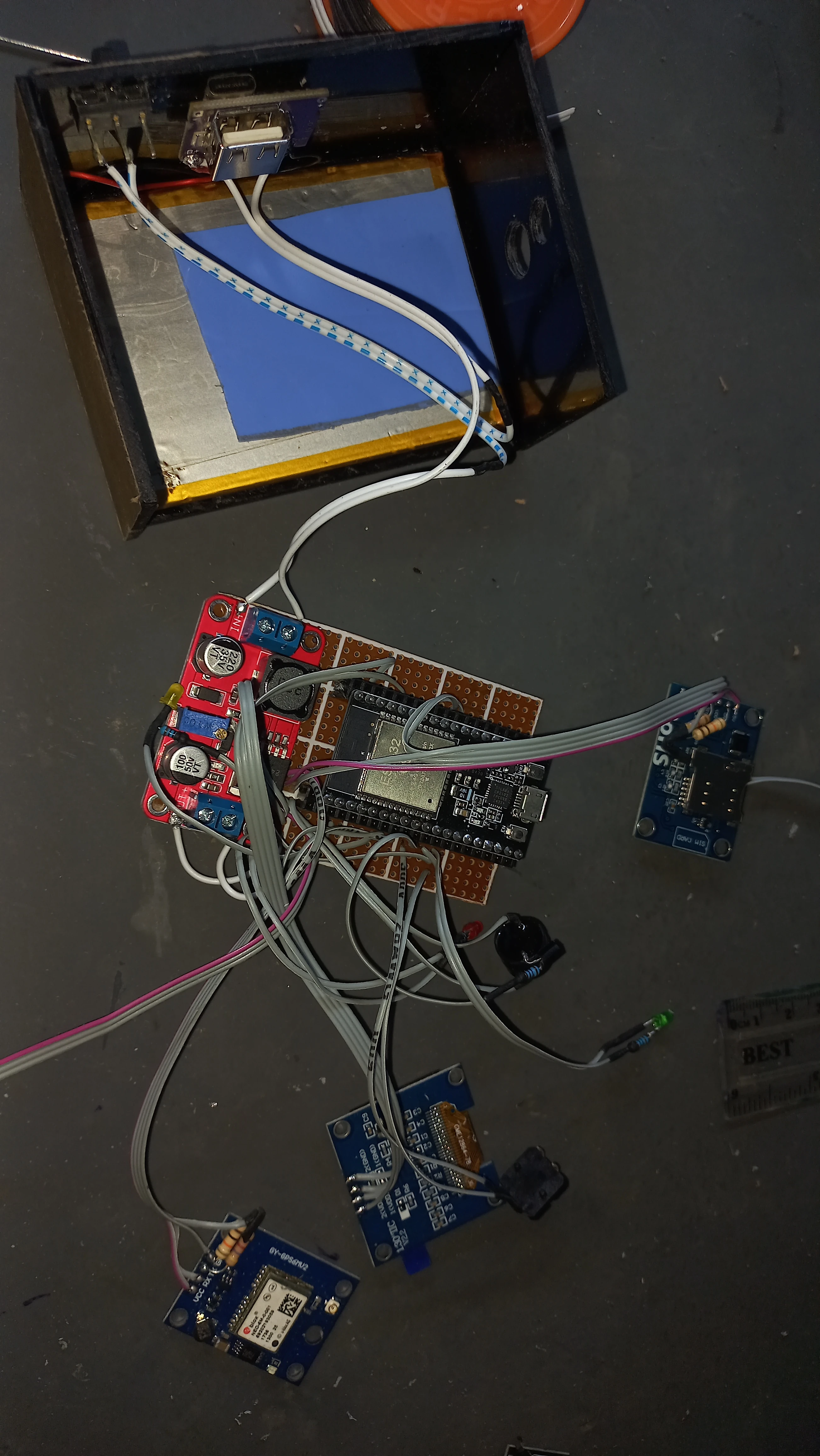
}The circuit was designed in Proteus and exported as both a colour schematic and a black-and-white reference diagram. The final PCB was hand-soldered on a 9×15 cm copper perfboard with female header rows for all removable modules.
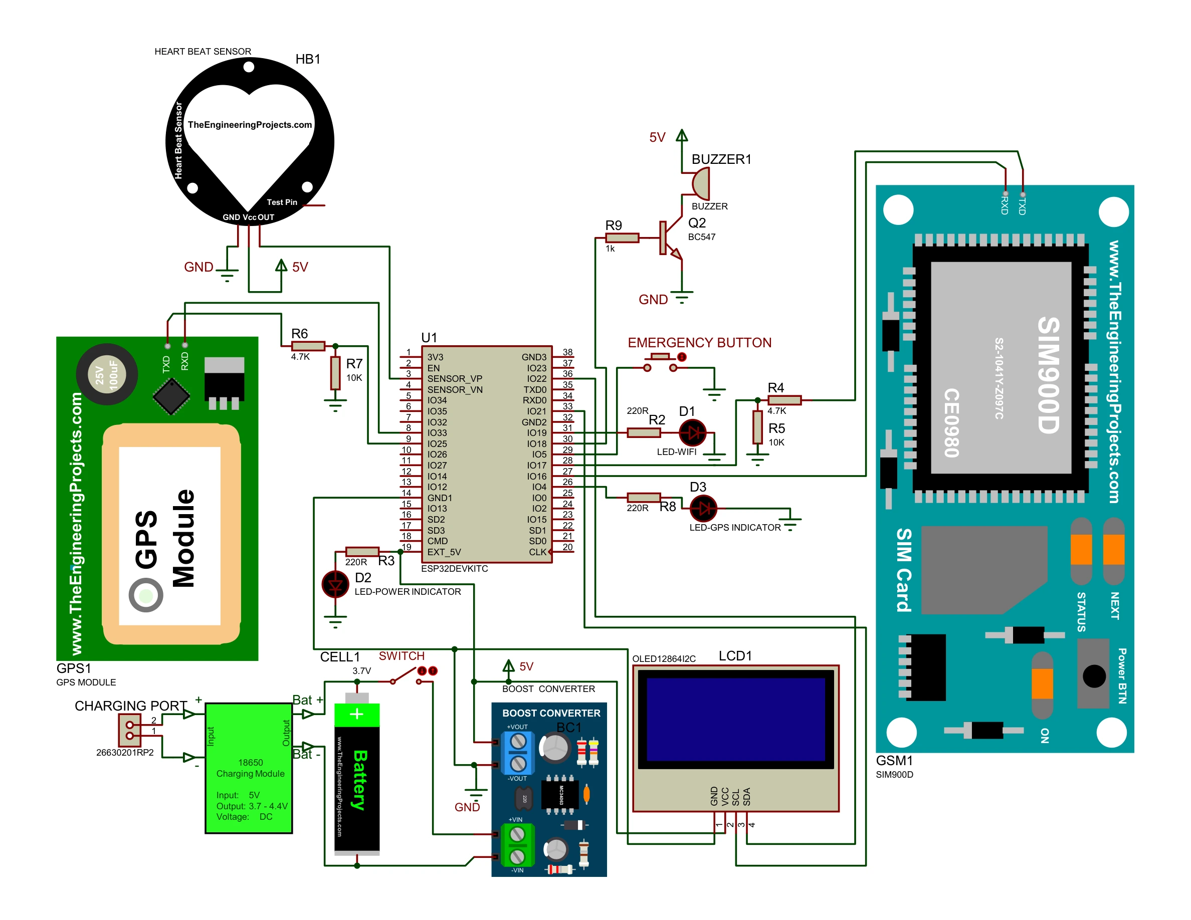
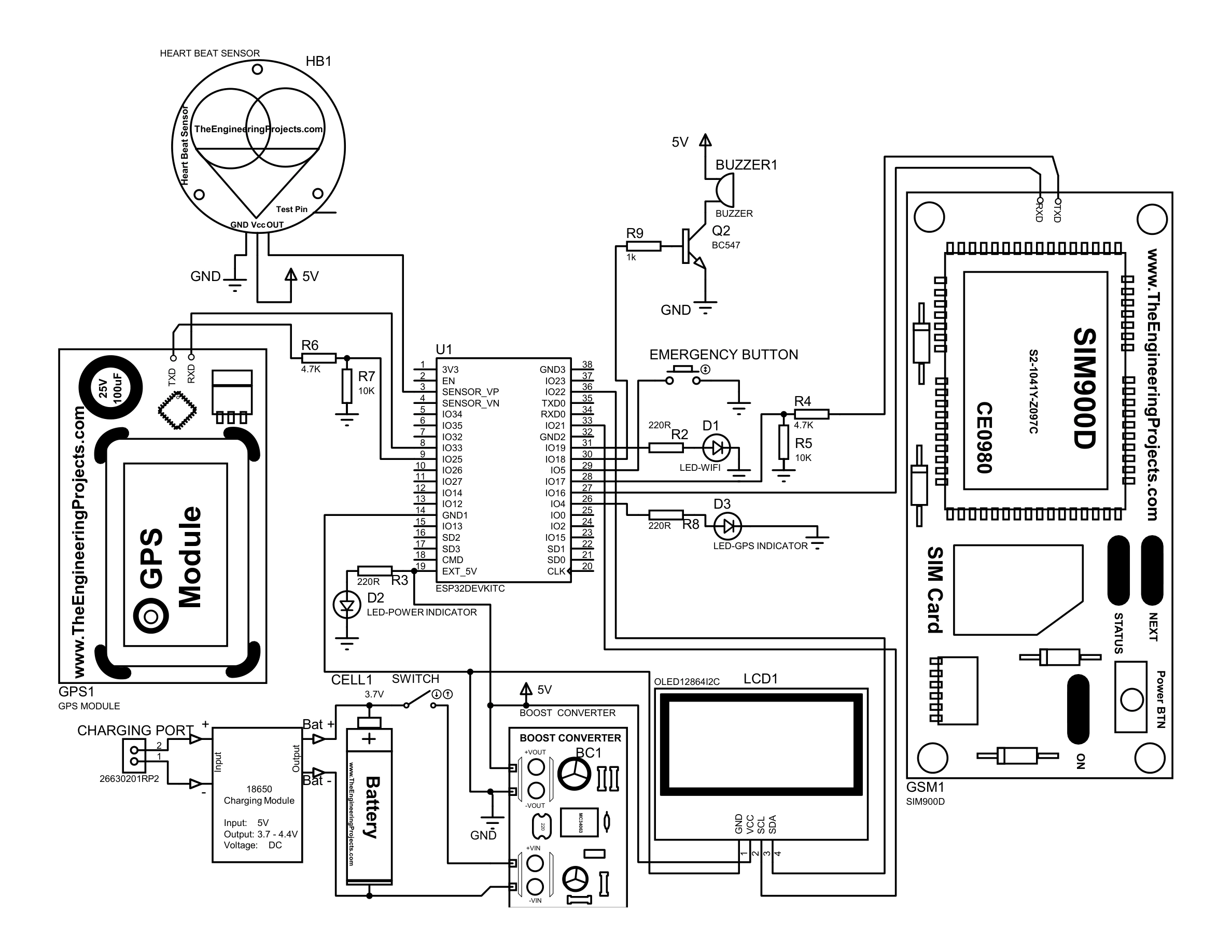
The complete sketch is ~600 lines of Arduino/C++. Below are the three most architecturally significant excerpts. All six subsystems in loop() use millis()-based timers so none block the others.
// 50 ms debounce + duration measurement for dual-trigger button
int rawButtonState = digitalRead(BUTTON_PIN);
if (rawButtonState != lastRawButtonState) lastDebounceTime = currentMillis;

if ((currentMillis - lastDebounceTime) > DEBOUNCE_DELAY) {  // 50 ms
    if (rawButtonState != stableButtonState) {
        stableButtonState = rawButtonState;
        if (stableButtonState == LOW) {   // pressed
            buttonPressStart = currentMillis;
            buttonPressed = true;
        } else {                          // released
            buttonPressed = false;
            unsigned long pressDuration = currentMillis - buttonPressStart;
            if (pressDuration >= LONG_PRESS_TIME) {   // >= 2000 ms
                triggerSafe();
            } else if (pressDuration > 50) {          // short press
                if (!alertActive) triggerDanger("Manual Panic Button Pressed!");
            }
        }
    }
}
lastRawButtonState = rawButtonState;// Three 200 ms beeps then 3 s silence, cycling while alertActive
if (alertActive) {
if (!inSilencePeriod) {
if (currentMillis - lastBuzzerTime >= 200) {
buzzerState = !buzzerState;
digitalWrite(BUZZER_PIN, buzzerState ? HIGH : LOW);
lastBuzzerTime = currentMillis;
if (!buzzerState) { // falling edge = one beep completed
beepCount++;
if (beepCount >= 3) { // three beeps done
inSilencePeriod = true;
beepCount = 0;
}
}
}
} else {
if (currentMillis - lastBuzzerTime >= 3000) {
inSilencePeriod = false;
lastBuzzerTime = currentMillis;
}
}
}void sendSMS(String phoneNumber, String message) {
// Show "SENDING SMS..." on OLED during the blocking AT sequence
display.firstPage();
do {
display.setFont(u8g2_font_6x10_tf);
display.drawStr(10, 30, "SENDING SMS...");
display.drawStr(10, 45, "Please Wait.");
} while (display.nextPage());
GSM_SERIAL.println("AT"); delay(500);
GSM_SERIAL.println("AT+CMGF=1"); delay(500); // text mode
GSM_SERIAL.println("AT+CMGS=\"" + phoneNumber + "\""); delay(500);
GSM_SERIAL.print(message); delay(500);
GSM_SERIAL.write(26); // Ctrl+Z = send
delay(2000);
}void setup() {
Serial.begin(115200);
pinMode(BUTTON_PIN, INPUT_PULLUP);
pinMode(BUZZER_PIN, OUTPUT);
pinMode(WIFI_LED_PIN, OUTPUT);
pinMode(GPS_LED_PIN, OUTPUT);
digitalWrite(BUZZER_PIN, LOW);
digitalWrite(WIFI_LED_PIN, LOW);
digitalWrite(GPS_LED_PIN, LOW);
Wire.begin();
display.begin();
showBootScreen(); // 3-second splash: project title + student ID
GPS_SERIAL.begin(115200, SERIAL_8N1, GPS_RX_PIN, GPS_TX_PIN); // UART2
GSM_SERIAL.begin(115200, SERIAL_8N1, GSM_RX_PIN, GSM_TX_PIN); // UART1
delay(3000);
GSM_SERIAL.println("AT+CMGF=1"); // set text mode
analogReadResolution(10);
pulseSensor.analogInput(PULSE_INPUT); // GPIO 36
pulseSensor.blinkOnPulse(PULSE_BLINK); // GPIO 2
pulseSensor.setThreshold(THRESHOLD); // 550
pulseSensor.begin();
connectToWiFi();
timeClient.begin();
timeClient.update();
setupFirebase();
}
void showBootScreen() {
display.firstPage();
do {
display.setFont(u8g2_font_6x10_tf);
display.drawStr(10, 12, "SMART SAFETY");
display.drawStr(25, 24, "DEVICE");
display.drawHLine(0, 30, 128);
display.drawStr(0, 42, "UGWOKE CHIZARAM P.");
display.drawStr(0, 54, "21CK029347");
} while (display.nextPage());
delay(3000);
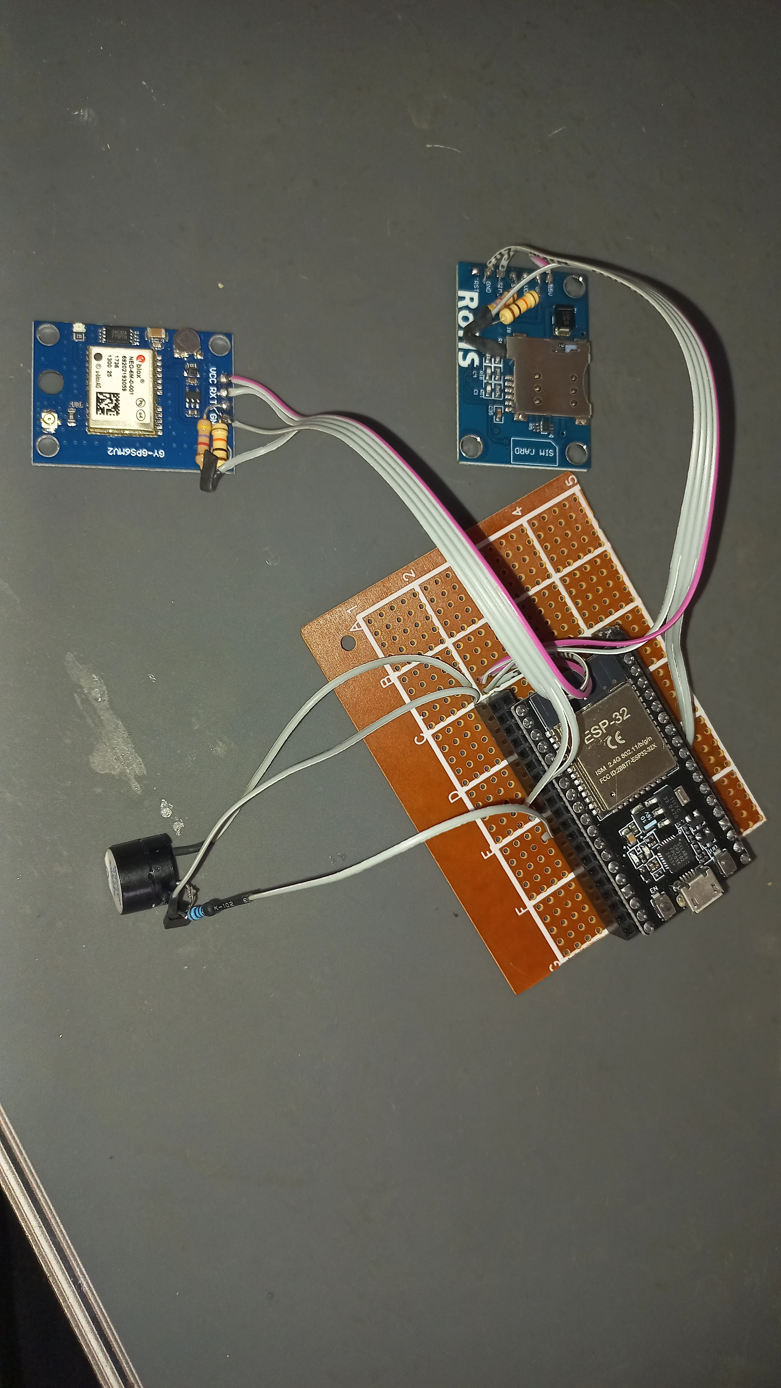
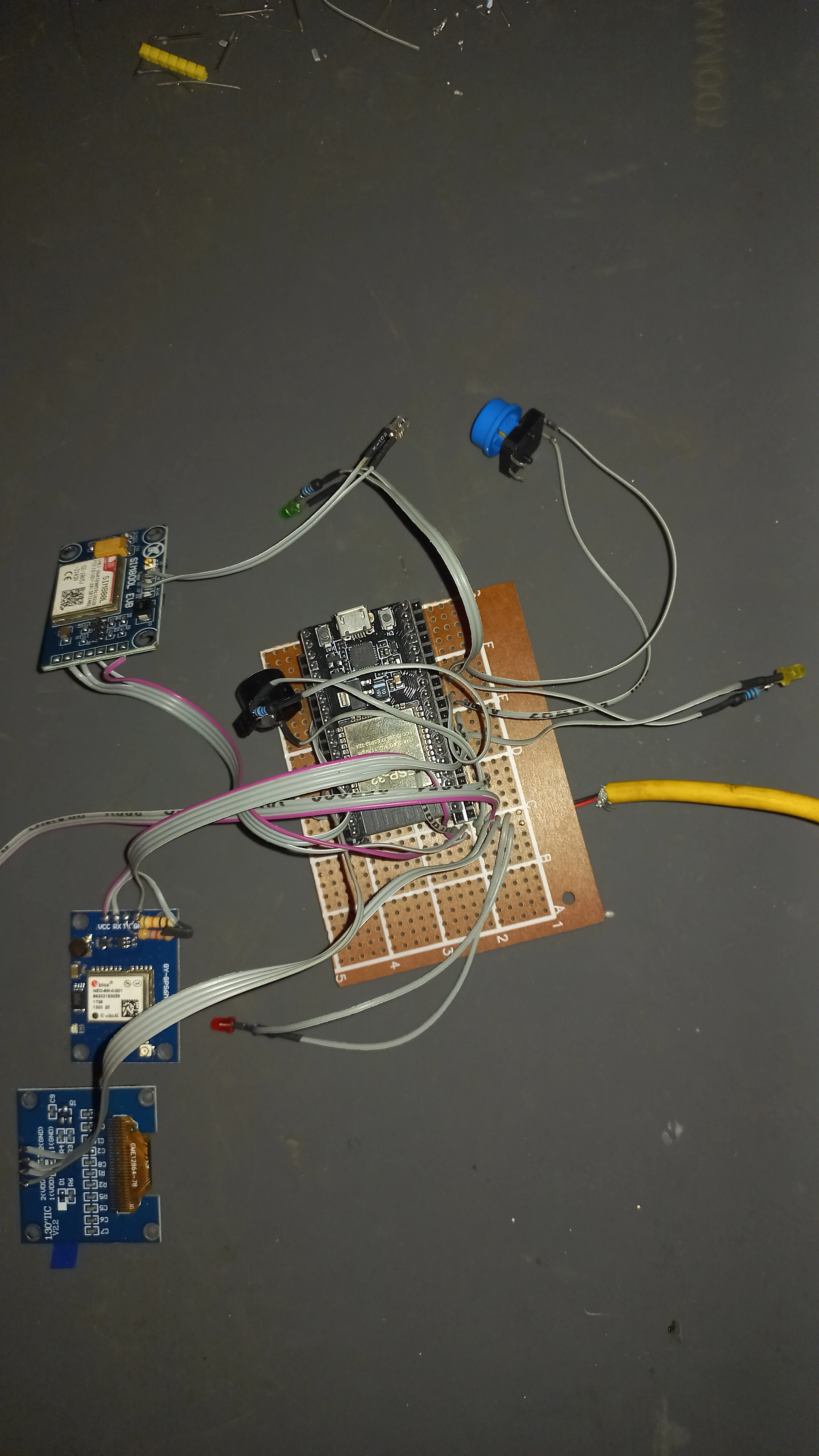
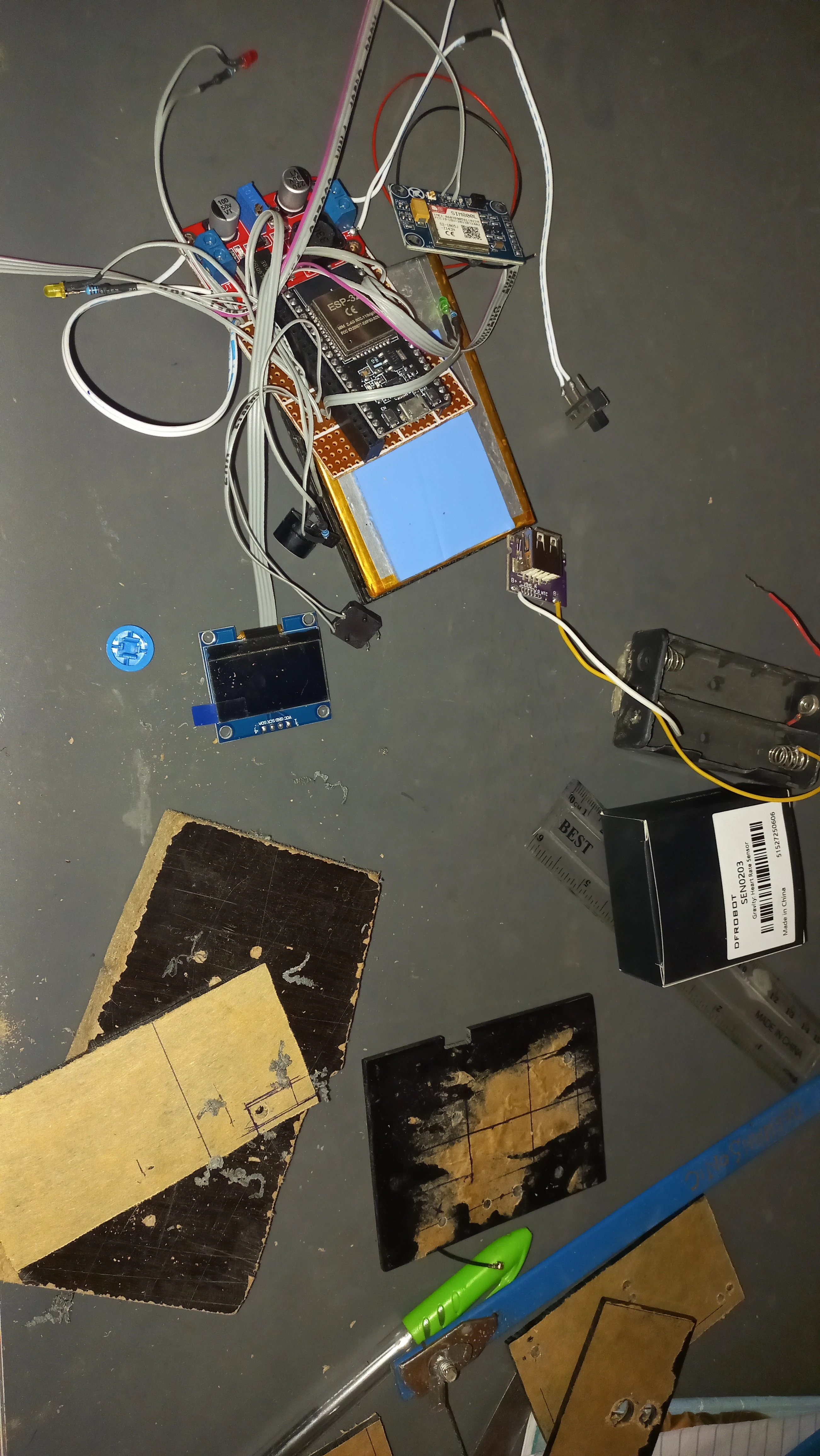
}75 photos documenting the project from individual components through PCB assembly, enclosure integration, and final live demonstration.


I sincerely appreciate you taking the time to explore my portfolio and learn about my work and expertise. If you have any questions or wish to discuss potential collaborations, please feel free to reach out via the Contact section.
Best regards,
Damilare Lekan, Adekeye.