Smart Assistive Traffic System with Haptic Wearable for the Visually and Hearing Impaired
ESP-NOW Wireless Haptic Communication, FFT Siren Detection, and Road Traffic Management
Category: IoT • Assistive Technology • Digital Signal Processing • Embedded Systems
Tools & Technologies: 2× ESP32, ESP-NOW Wireless Protocol, MAX4466 High-Sensitivity
Microphone, FFT (Fast Fourier Transform), Haptic Vibration Motor, 20×4 I2C LCD Display (PCF8574
backpack), LM2596 Buck Converter, TP4056 USB-C Charger, HWE 18650 E6 Battery, Arduino IDE
Status: Completed
Project Overview
This system bridges the accessibility gap at road crossings for pedestrians with visual or hearing
impairments. It consists of two nodes: a Road Unit (infrastructure) and a Hangable Wearable Unit
(assistive device worn at the belt or pocket).
The Road Unit manages a traffic light cycle (90 s vehicle phase / 30 s pedestrian phase) and
monitors for emergency vehicle sirens using FFT spectral analysis on the MAX4466 microphone,
detecting the characteristic frequency sweep of ambulances and fire trucks (400–2500 Hz).
When a crossing state changes or a siren is detected, the road unit broadcasts the event
wirelessly via ESP-NOW to the wearable.
The Wearable Unit translates road data into a distinct haptic language of vibration patterns:
a 10-second continuous vibration when vehicles are moving (danger), a rhythmic triple-burst
pattern during safe pedestrian crossing, and rapid 100 ms pulses during emergency override.
A 2-second heartbeat ping from the wearable back to the road unit creates a connection-loss
safety alert if the pedestrian moves out of range.
Live demonstration: The completed system was tested and demonstrated with both
units operating in real time. The road model physical prop, built from PVC board and vinyl
materials, was used to present the system at demonstration. All three haptic patterns and the
FFT-based siren detection were verified during testing.
Key Features
- ESP-NOW peer-to-peer wireless: no Wi-Fi router, no internet dependency,
ultra-low latency communication between the two ESP32 units
- FFT-based intelligent siren detection: MAX4466 microphone feeds audio into
FFT spectral analysis; ambulance and fire truck frequency sweep (400–2500 Hz) detected
in real time
- 3-state haptic language: Danger (continuous 10 s vibration during vehicle
phase), Walk (triple-burst pattern during pedestrian phase), Emergency (rapid 100 ms pulses
on siren detection)
- Bidirectional heartbeat: wearable pings road unit every 2 s; connection
loss triggers a safety alert on both devices simultaneously
- Three intelligent emergency scenarios: siren during vehicle phase, siren
during pedestrian phase, and a full recovery protocol that resets to a 90 s vehicle phase
after the siren clears
- 20×4 I2C LCD on road unit: displays live phase name, countdown
timer, and wearable connection status; driven via PCF8574 I2C backpack
- Blue LED connectivity indicator: fitted on both units to show whether the
ESP-NOW link is active
- Self-contained power systems: road unit powered from a 12 V AC adapter
regulated to 5 V via LM2596 buck converter; wearable runs on a 3200 mAh 18650 LiPo cell
with USB-C charging via TP4056
System Architecture
The system operates as two cooperating ESP32 nodes communicating exclusively over ESP-NOW with
no infrastructure requirement. The road unit owns the traffic state machine and all sensing;
the wearable unit owns the haptic output and the user-facing experience.
Road Unit (ESP32 #1)
12 V AC Adapter → LM2596 Buck Converter → 5.16 V regulated rail
↓
MAX4466 Microphone → ADC sampling
↓
FFT Analysis: 400–2500 Hz siren sweep detection
↕
Traffic Cycle State Machine
90 s VEHICLE → 30 s PEDESTRIAN
↓
Emergency Override: siren detected → all-red + alert broadcast
↓
20×4 I2C LCD (PCF8574): phase + countdown + wearable status
↓
ESP-NOW TX → phase event + siren flag broadcast
Wearable Unit (ESP32 #2)
TP4056 USB-C → 18650 3200 mAh LiPo → ESP32 Vin
↓
ESP-NOW RX: phase event received from road unit
↓
PEDESTRIAN phase → triple-burst haptic pattern
(100 ms on ×3 + 1.5 s pause, repeating)
↕
VEHICLE phase → 10 s continuous vibration (danger alert)
↕
EMERGENCY → rapid 100 ms pulse bursts (siren active)
↓
Blue LED: connection status indicator
↓
Heartbeat ping → road unit every 2 s (link-loss detection)
Hardware Components
| Component |
Model / Specification |
Unit |
Role |
| Microcontroller (Road) |
ESP32 Dev Board |
Road Unit |
Traffic state machine, FFT siren detection, ESP-NOW TX, LCD driver |
| Microcontroller (Wearable) |
ESP32 Dev Board |
Wearable Unit |
ESP-NOW RX, haptic motor control, heartbeat ping, LED indicator |
| Microphone Module |
GY MAX4466 High-Sensitivity Electret Microphone Amplifier |
Road Unit |
Audio capture for FFT-based siren frequency analysis |
| Haptic Motor |
Coin-type vibration motor |
Wearable Unit |
Converts road phase events into tactile vibration patterns |
| LCD Display |
20×4 Character I2C LCD with PCF8574 backpack |
Road Unit |
Displays phase name, countdown timer, and wearable connection status |
| Traffic LEDs |
Red, amber, green LEDs |
Road Unit |
Physical traffic signal indicators for the road model demo |
| Status LEDs |
Red, green, blue LEDs |
Both Units |
Blue LED shows ESP-NOW link status; red/green indicate phase state |
| LiPo Battery |
HWE 18650 E6, 3200 mAh, 3.7 V, 11.84 Wh, with JST connector |
Wearable Unit |
Portable power source for the wearable unit |
| Charging Module |
TP4056 USB-C LiPo charger module |
Wearable Unit |
Manages LiPo charging with overcharge and over-discharge protection |
| Buck Converter |
LM2596 adjustable DC-DC step-down converter (set to 5.16 V output) |
Road Unit |
Regulates 12 V AC adapter output to stable 5 V logic rail |
| AC Adapter |
BT-branded 12 V / 2 A switching AC adapter |
Road Unit |
Mains power source for the road unit infrastructure installation |
| Mains Plug |
UK BS1363 3-pin plug (3 A, 250 V) |
Road Unit |
Connects AC adapter to mains socket |
| Enclosures |
Two white PVC electrical junction box cover plates (BS 4007) |
Both Units |
Houses all electronics for road unit and wearable unit respectively |
Circuit Diagram
Full Proteus circuit diagram showing both units: the wearable ESP32 with vibration motors,
TP4056 charger, 18650 battery, and boost converter; and the road unit ESP32 with MAX4466
microphone, 20x4 LCD, traffic and status LEDs, and 220V AC to 5V DC LM7805 power supply.
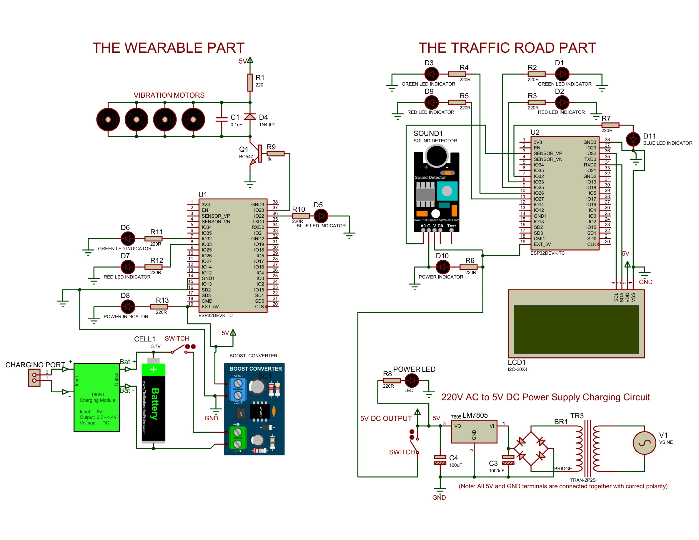
Circuit diagram (colour)
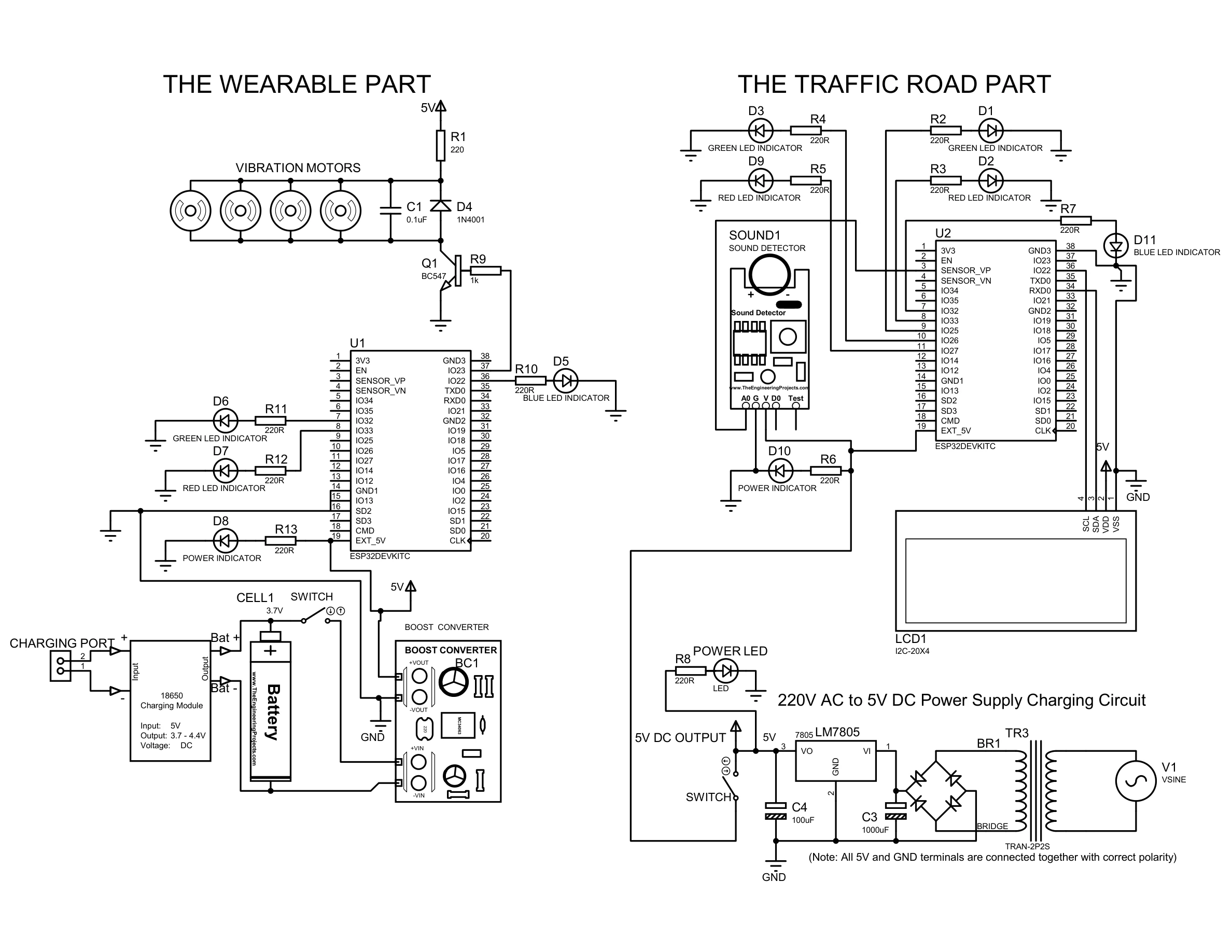
Circuit diagram (black and white)
Haptic Language Design
Rather than a simple on/off vibration, the wearable communicates three distinct states through
carefully designed vibration patterns that a visually or hearing-impaired user can learn and
interpret without any audio or visual feedback.
VEHICLE PHASE
Pattern: 10-second continuous vibration on crossing phase start.
Meaning: Vehicles are moving. Do not cross. Stay on the pavement.
Duration: 90-second vehicle phase; vibration fires at phase entry.
PEDESTRIAN PHASE
Pattern: Triple-burst: 100 ms vibration ×3 with 100 ms gaps,
then 1.5 s silence. Repeats for the full pedestrian phase.
Meaning: Safe to cross now.
Duration: 30-second pedestrian phase; pattern cycles continuously.
EMERGENCY OVERRIDE
Pattern: Rapid 100 ms pulse bursts, continuous, faster than the walk
pattern.
Meaning: Emergency vehicle detected. All lights red. Clear the road
immediately.
Trigger: FFT detects siren sweep (400–2500 Hz) on road unit
microphone.
Process and Methodology
The build spanned six weeks across two parallel tracks: physical road model construction for the
demonstration prop, and electronics hardware design, fabrication, and firmware development for
both ESP32 units. All work was documented in photographs from the first material cut through to
the final live demonstration.
Road Model: Material Preparation, April 2026

PVC board on workbench with hacksaw, set square, and marker: material preparation for the road model base board

Grid and road layout geometry penciled directly onto the PVC board before cutting
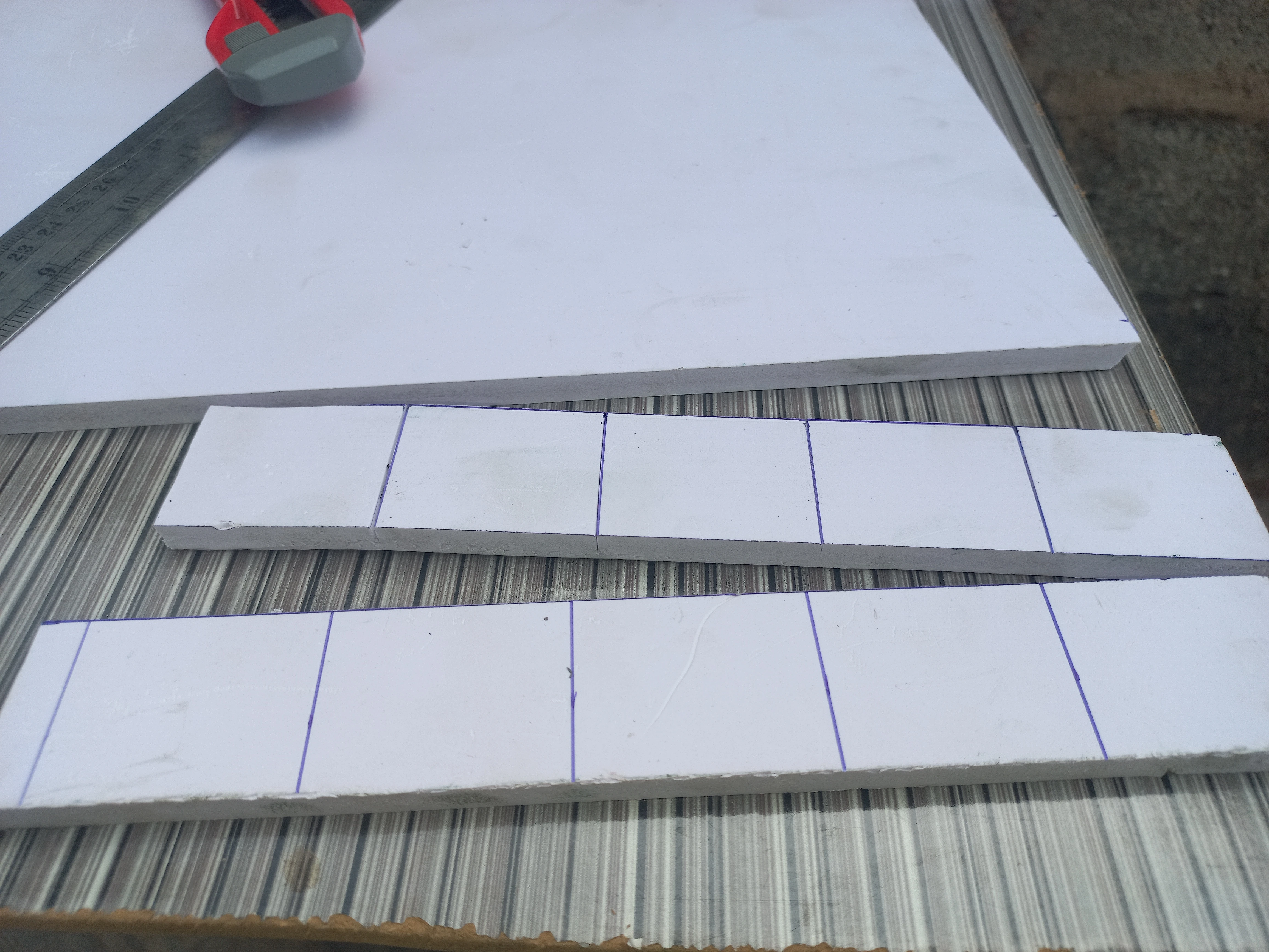
Strips of PVC board cut to width, ready for road surface arm construction

Foam tiles cut into uniform squares to form the road model surface layer

Cut foam tile squares stacked in a pile, ready for assembly onto the base board

PVC strip labeled 'ROAD' in black marker, test-fitted on the base board layout
Road Model: Surface Construction, April 2026
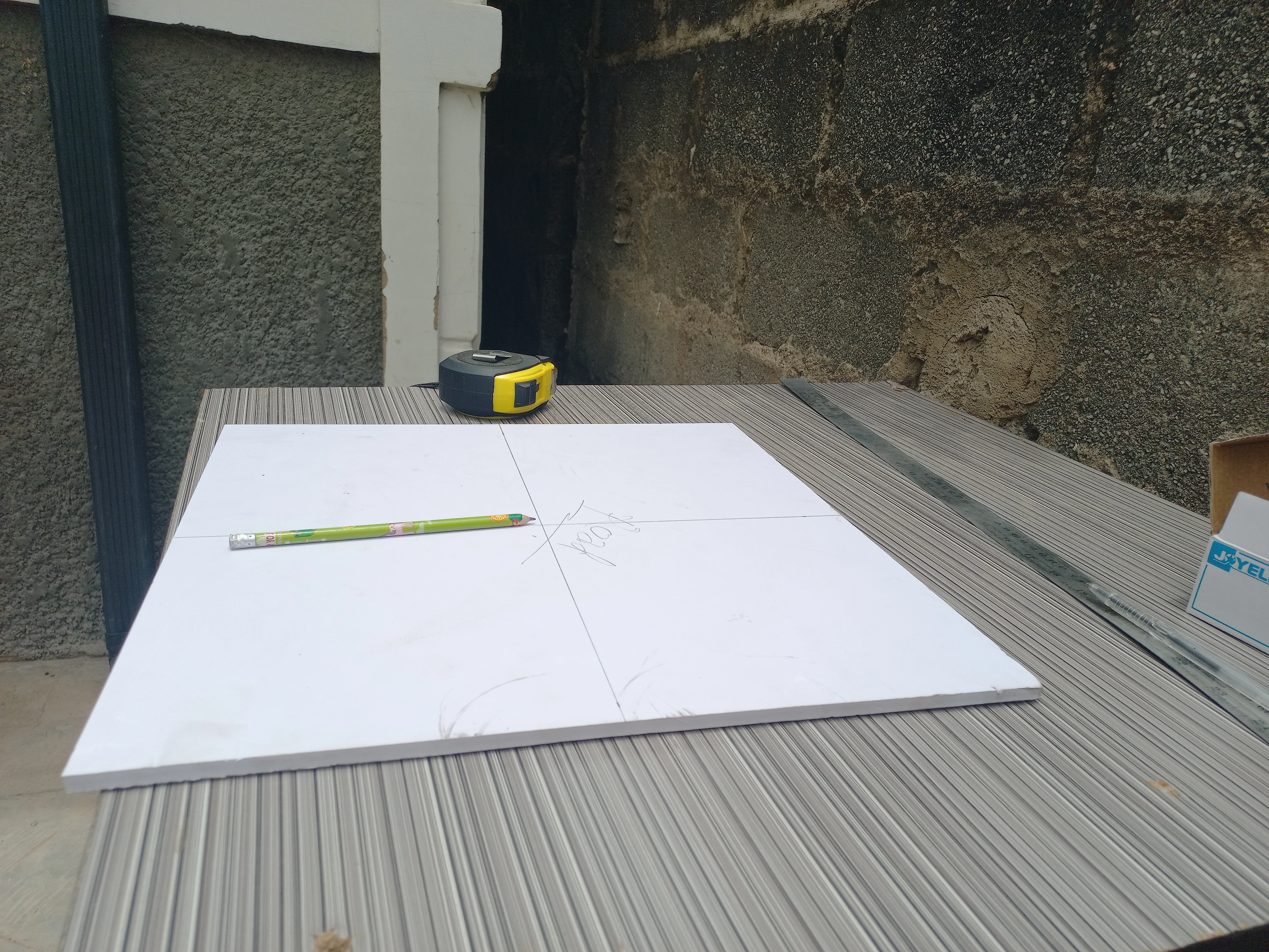
Base board flat on the workbench with the four-arm crossroads layout being planned out

All four crossroads arms outlined with black PVC strips on the white base board

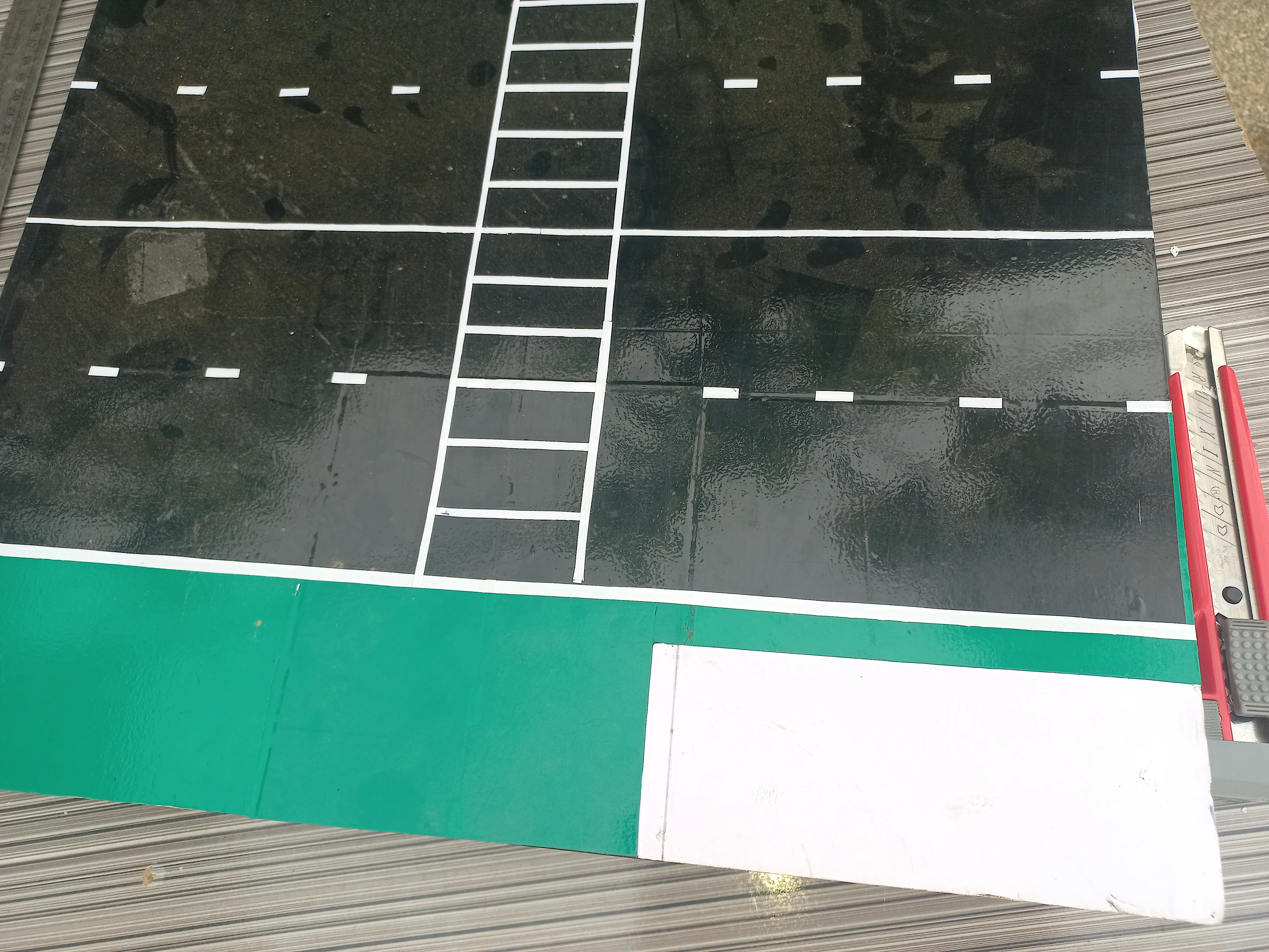
White dashed centre-line markings applied to two arms of the crossroads
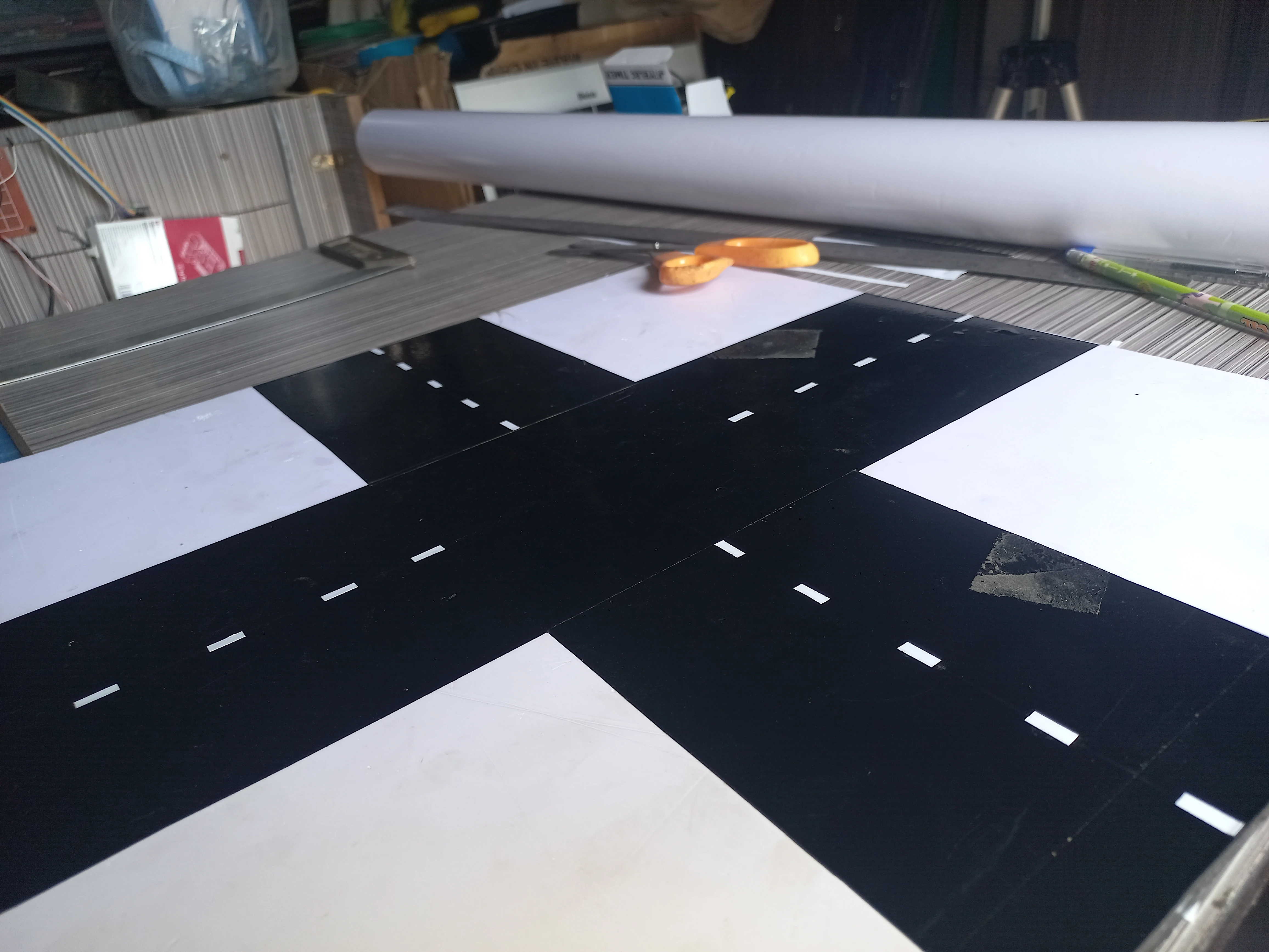
All four crossroads arms complete with dashed white centre-line markings
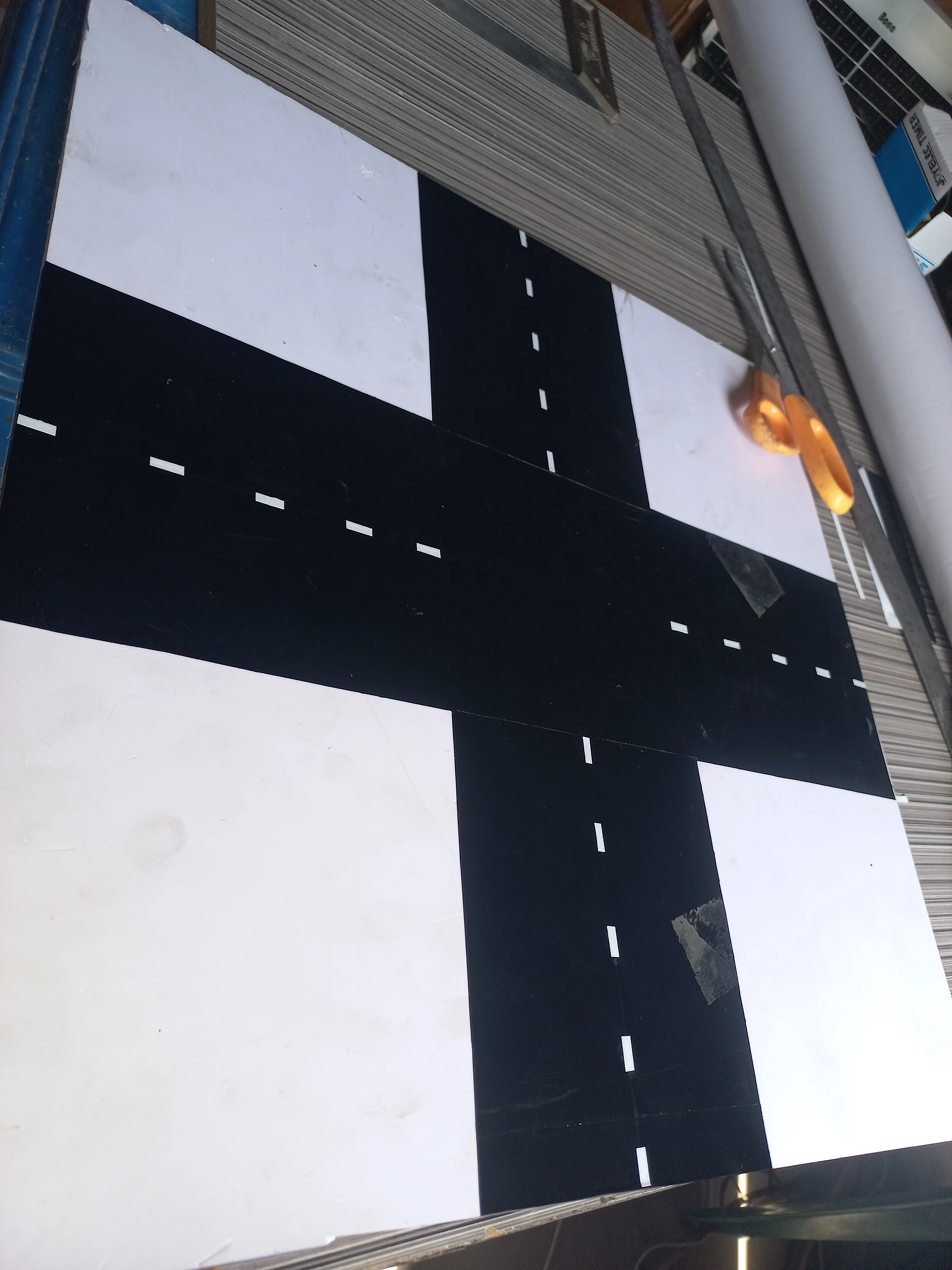
Overhead view of the crossroads road surface with all markings in place

Green vinyl roll and cut foam pieces prepared for the four corner grass areas of the model

Green vinyl squares cut and ready to be applied to the corner grass areas
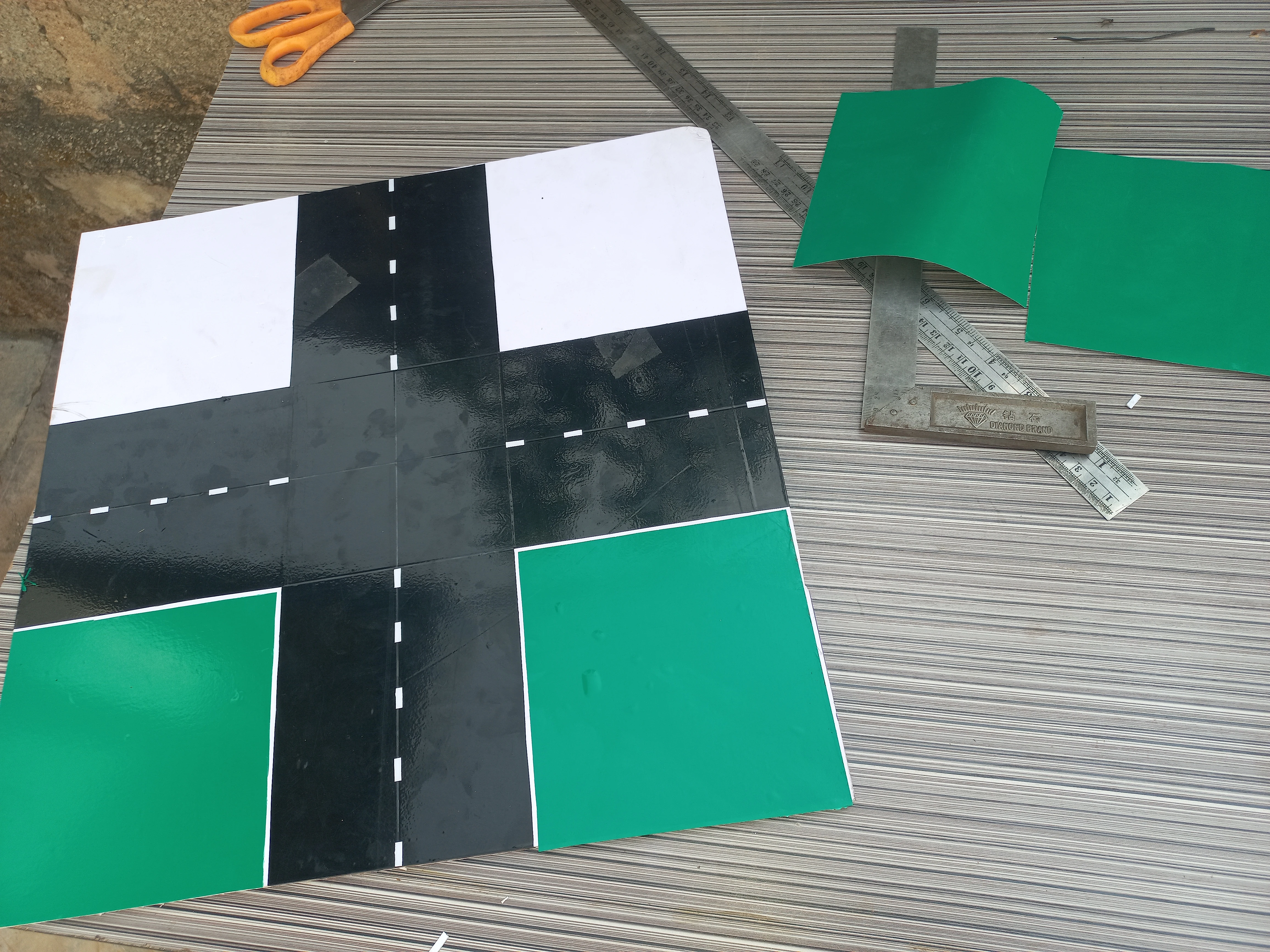
Road model with green vinyl applied to two corner areas; the two remaining corners still white
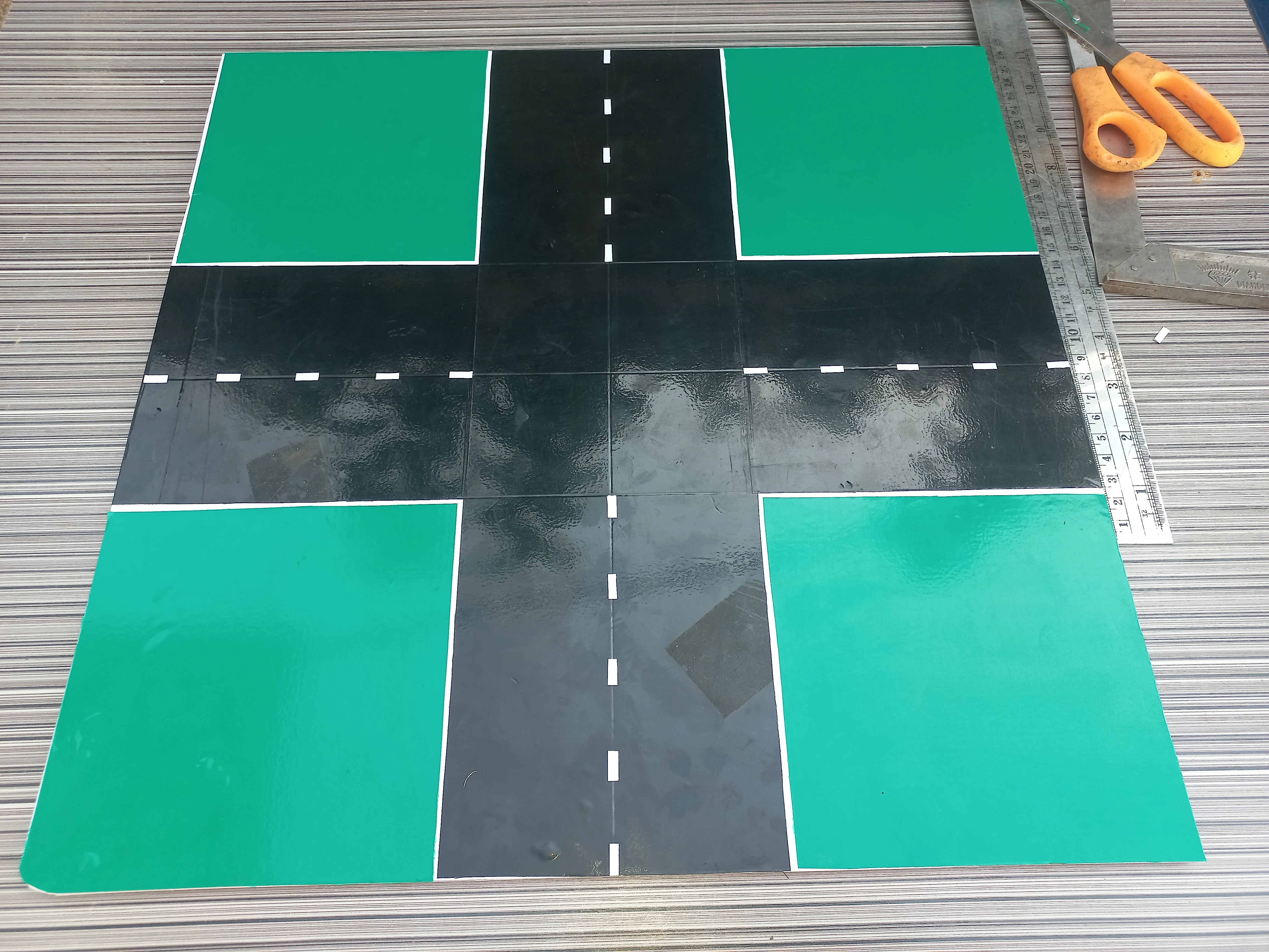
Road model with all four green vinyl grass corners complete
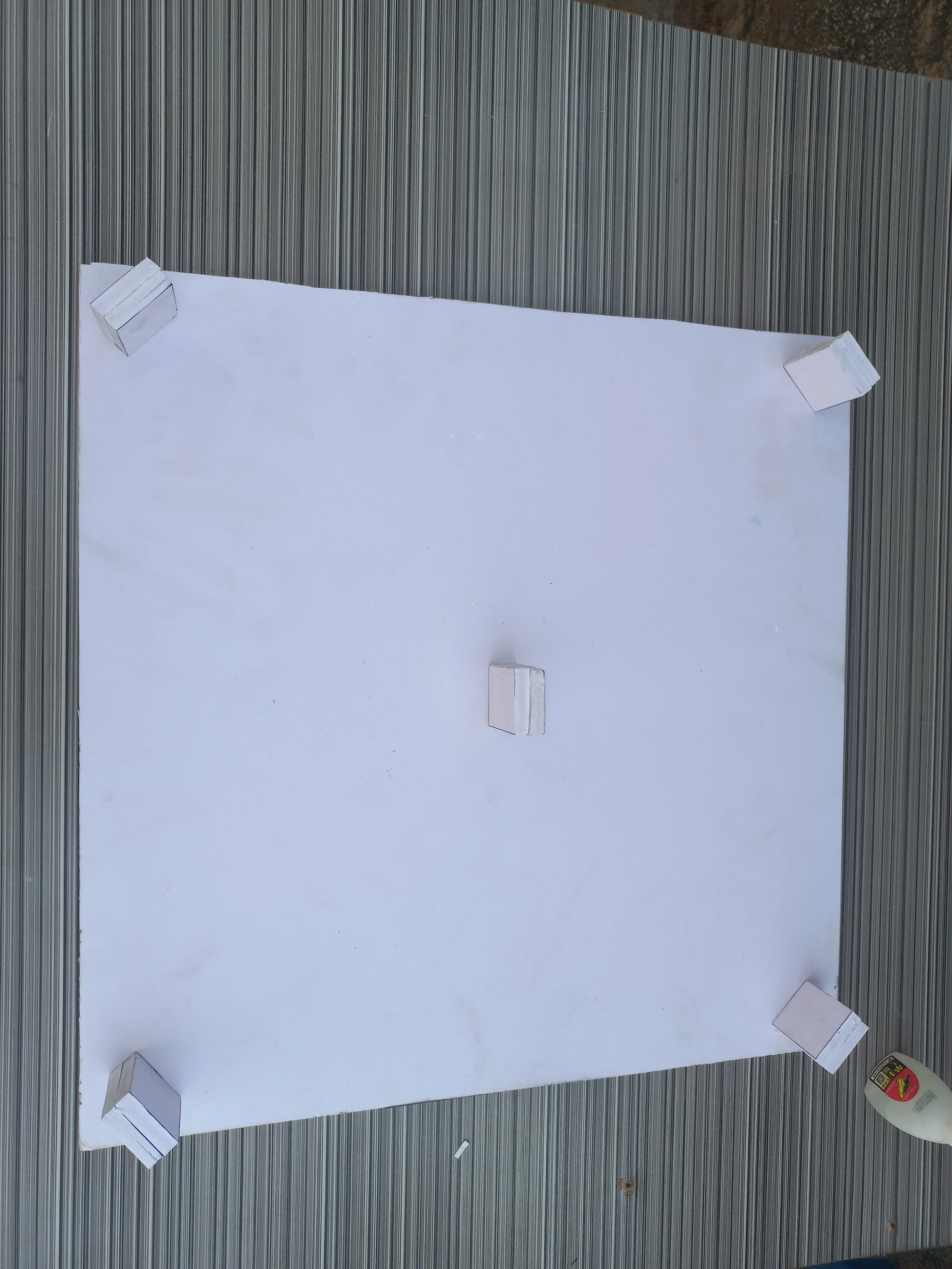
Underside of base board showing small wooden leg blocks glued at the corners for elevation
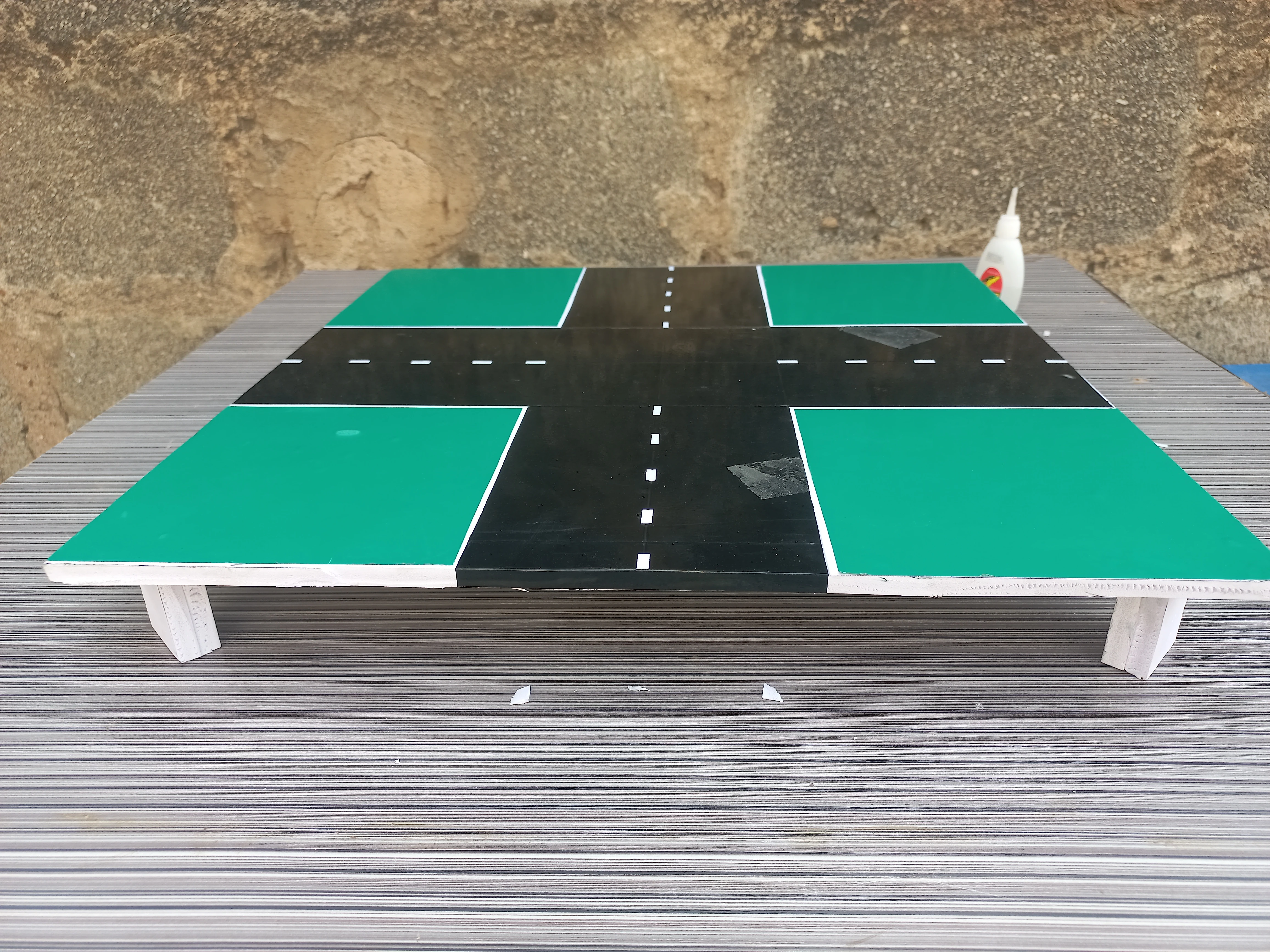
Road model elevated on its wooden leg blocks: full base structure assembled and standing
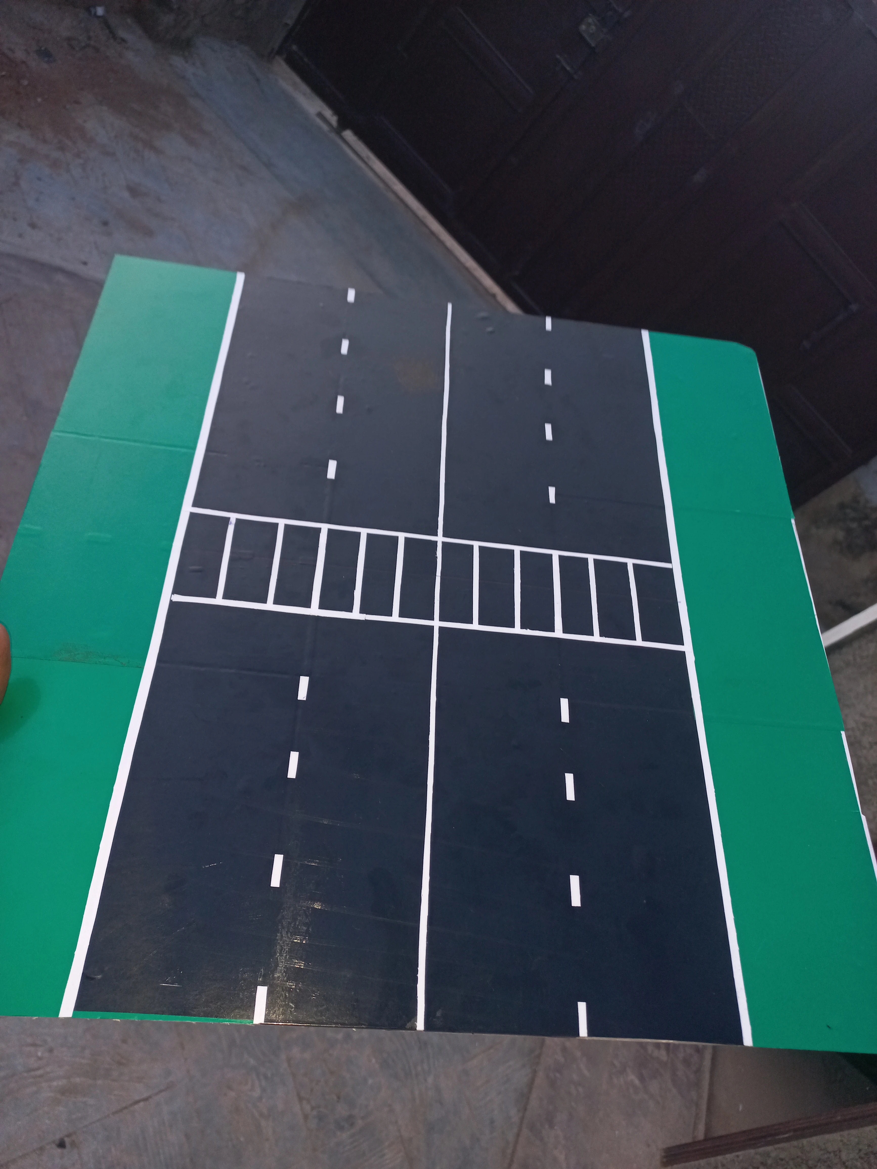
Completed road model with white zebra pedestrian crossing strips applied across one arm
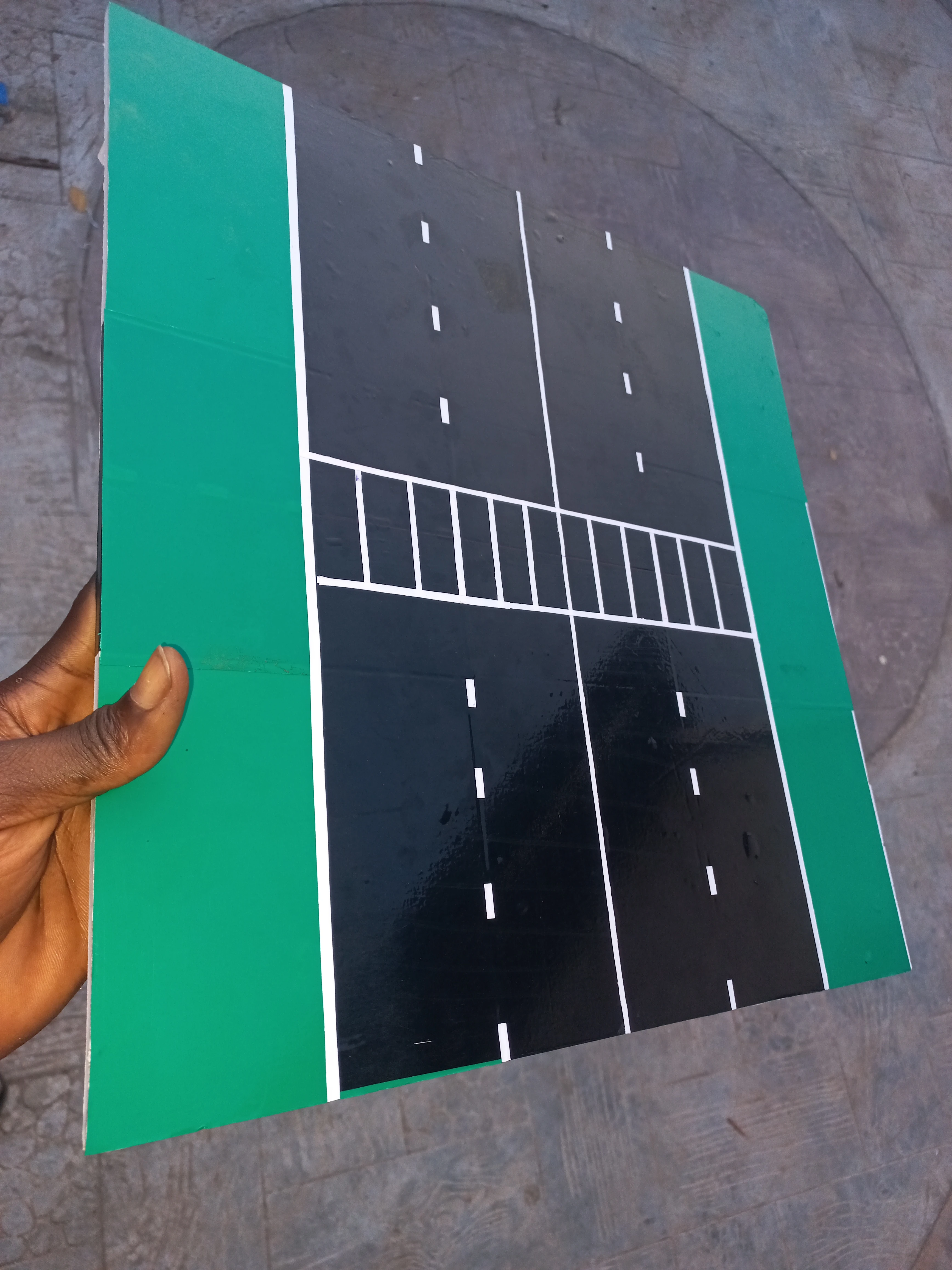
Developer holding the completed road model to show the pedestrian crossing and full road layout
Electronics Components, April 2026
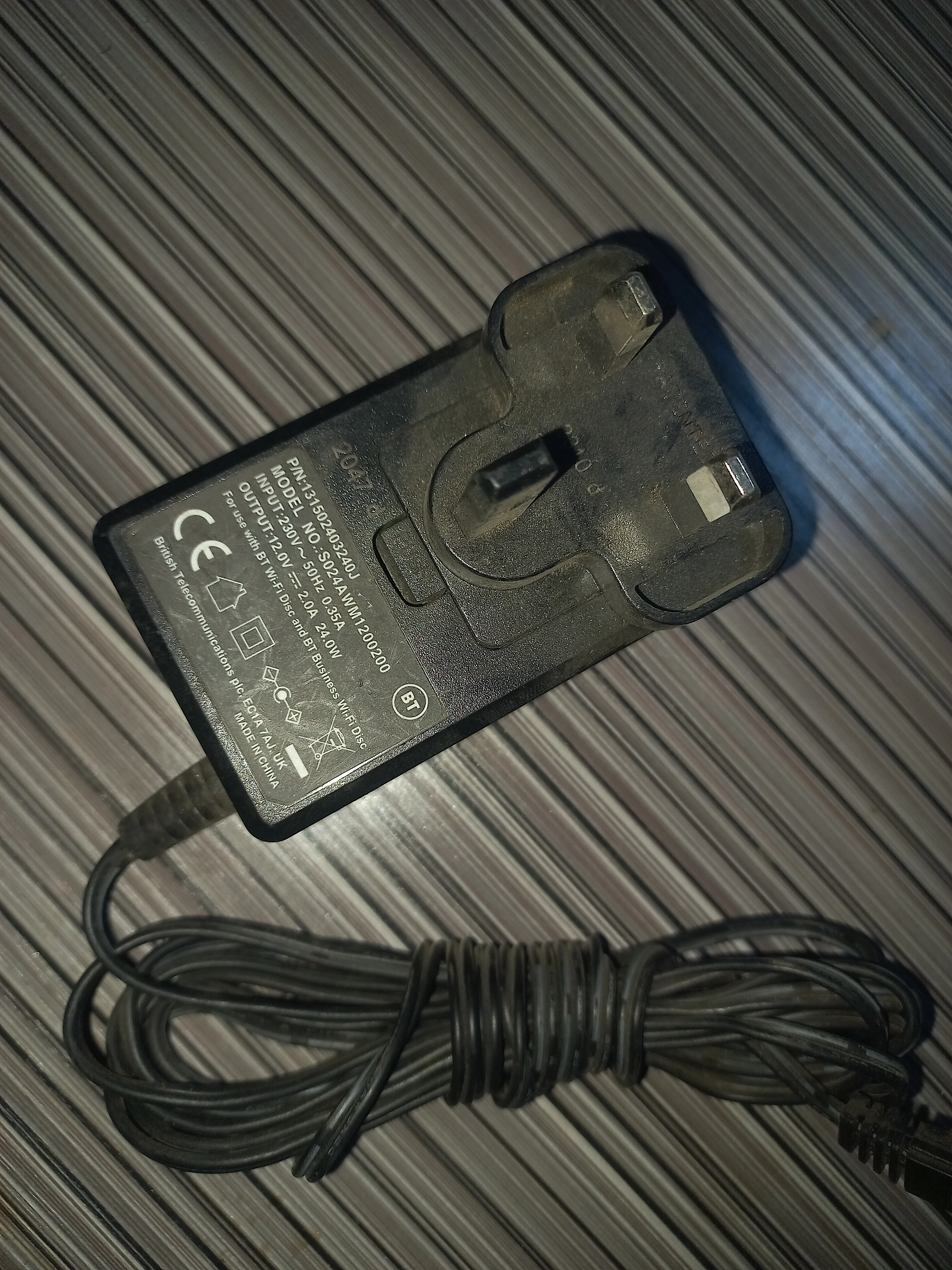
BT-branded 12 V/2 A AC adapter, the primary power supply for the road unit
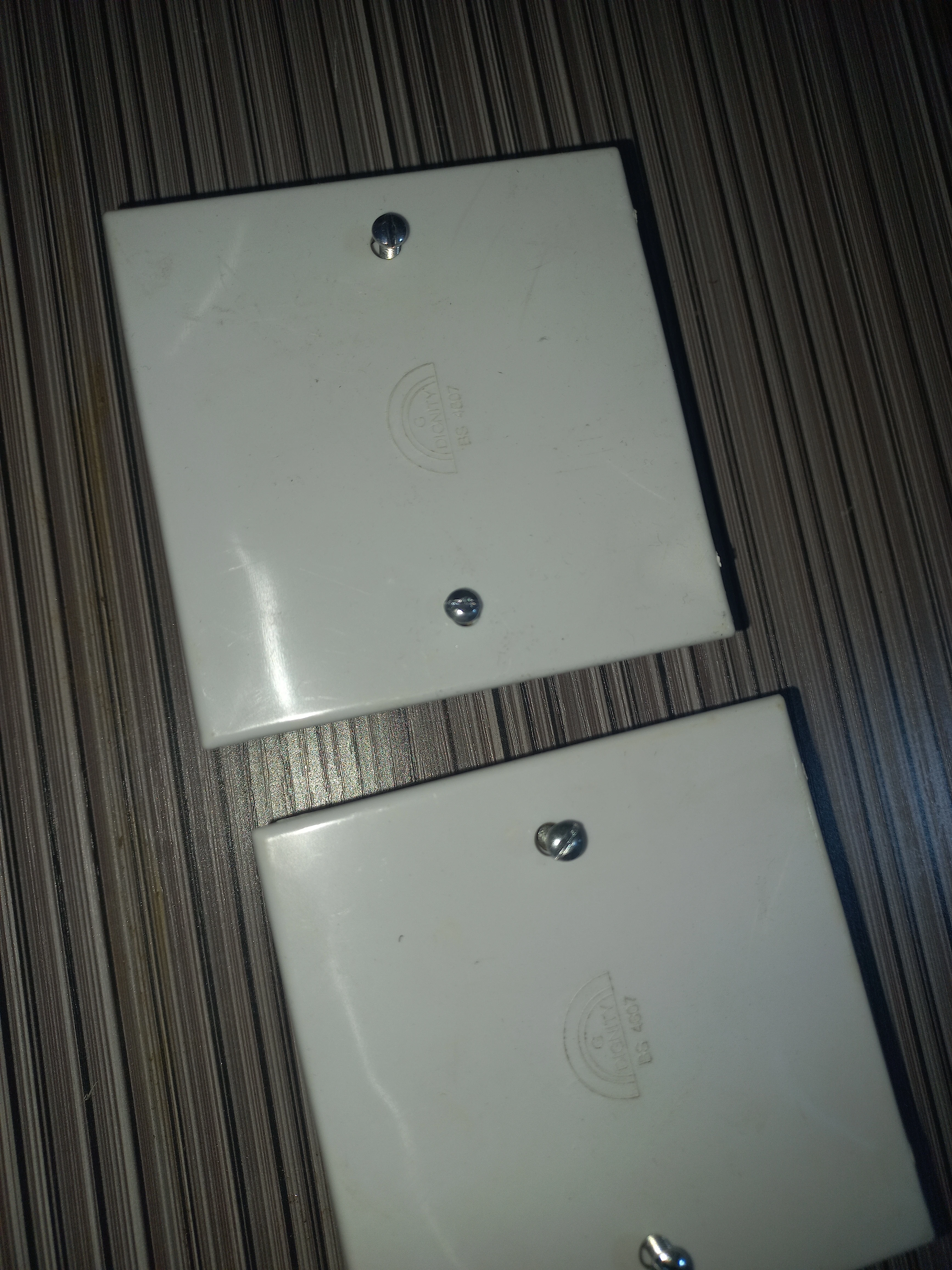
Two white PVC electrical junction box cover plates selected as enclosures for both units
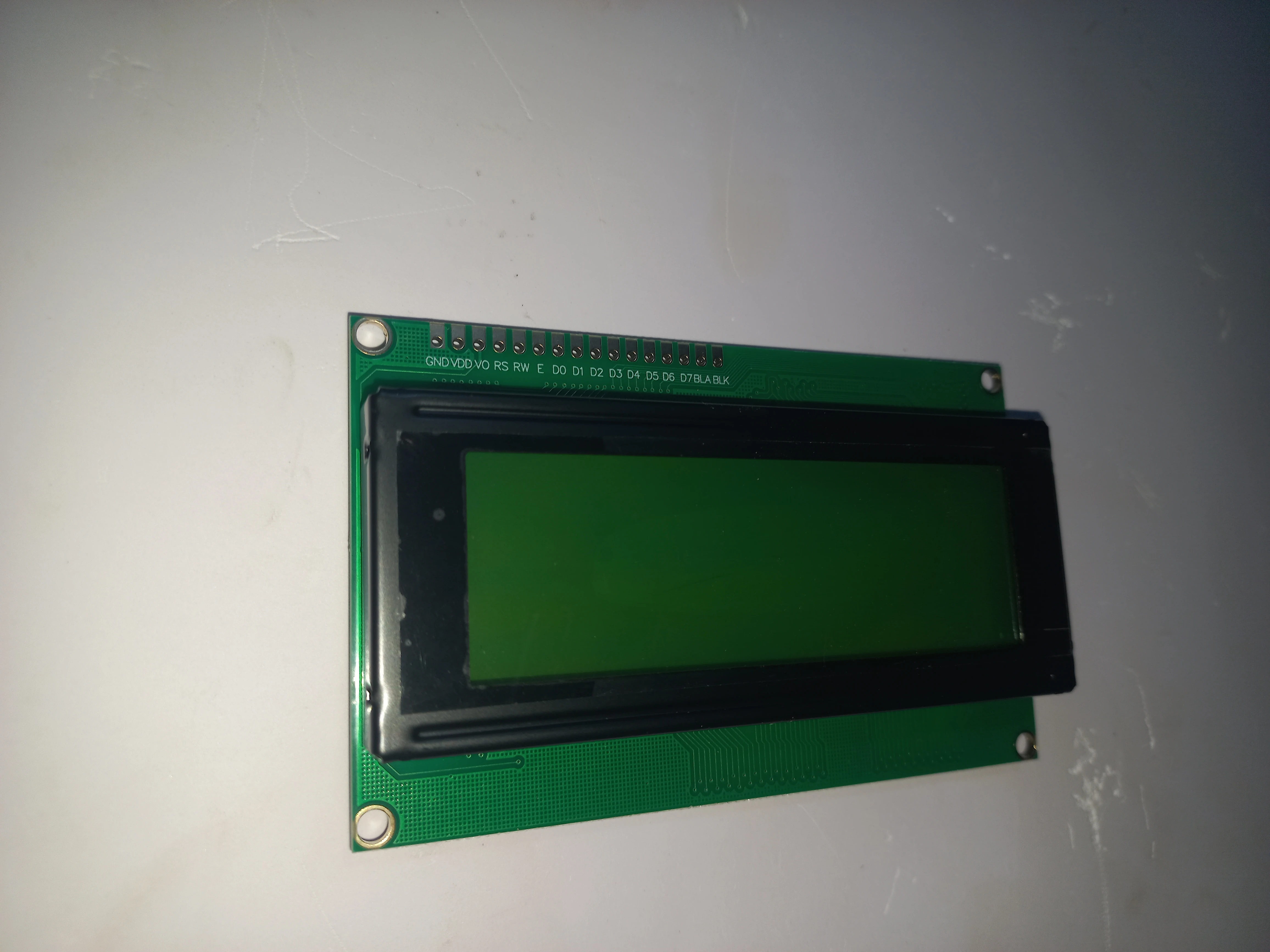
20x4 I2C LCD display module front face: used on the road unit for phase countdown and wearable status
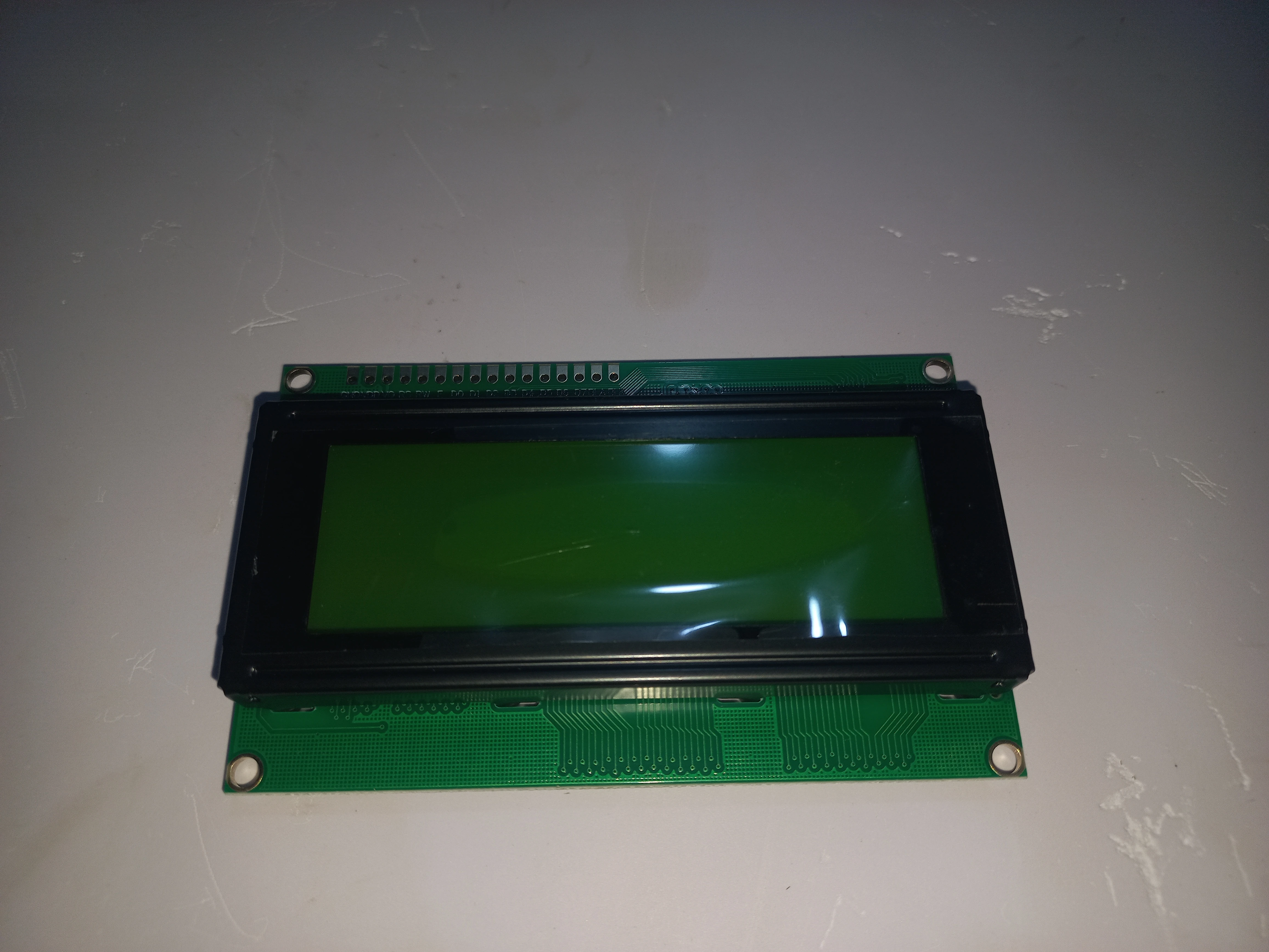
20x4 LCD module at a different angle showing the clear display glass
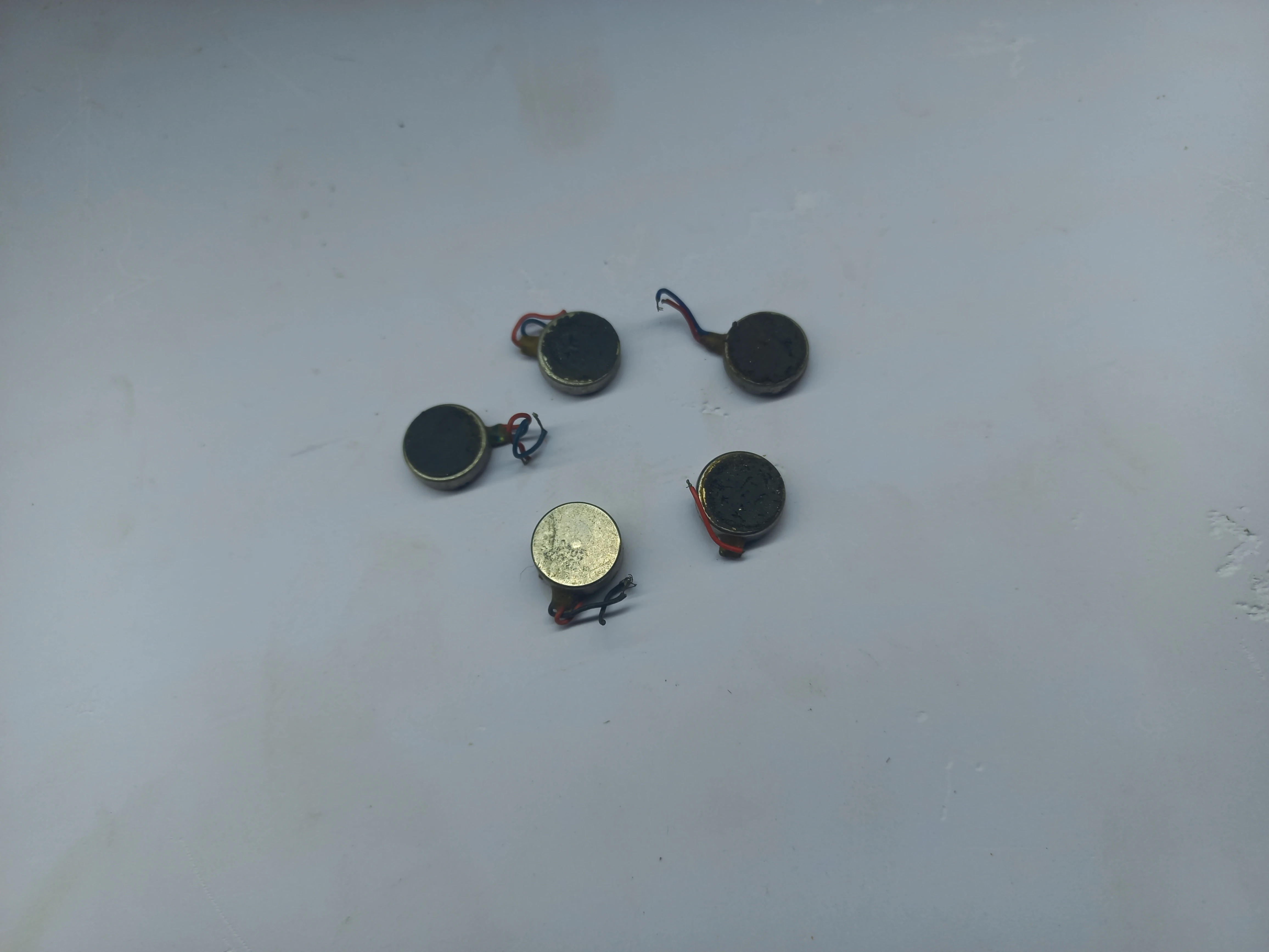
Coin-type vibration motors: the haptic actuators fitted inside the wearable unit
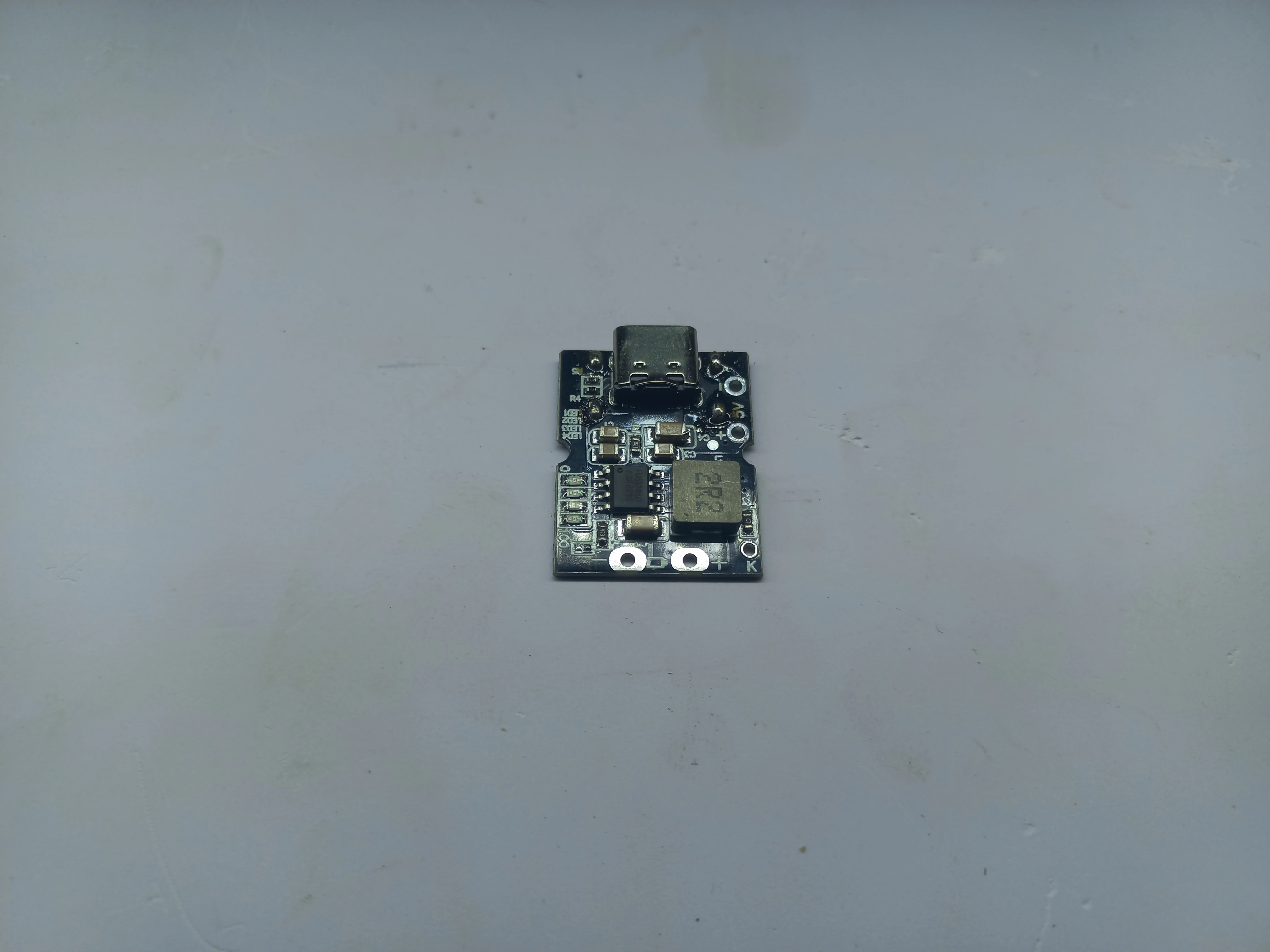
TP4056 USB-C LiPo charging module for the wearable unit battery management
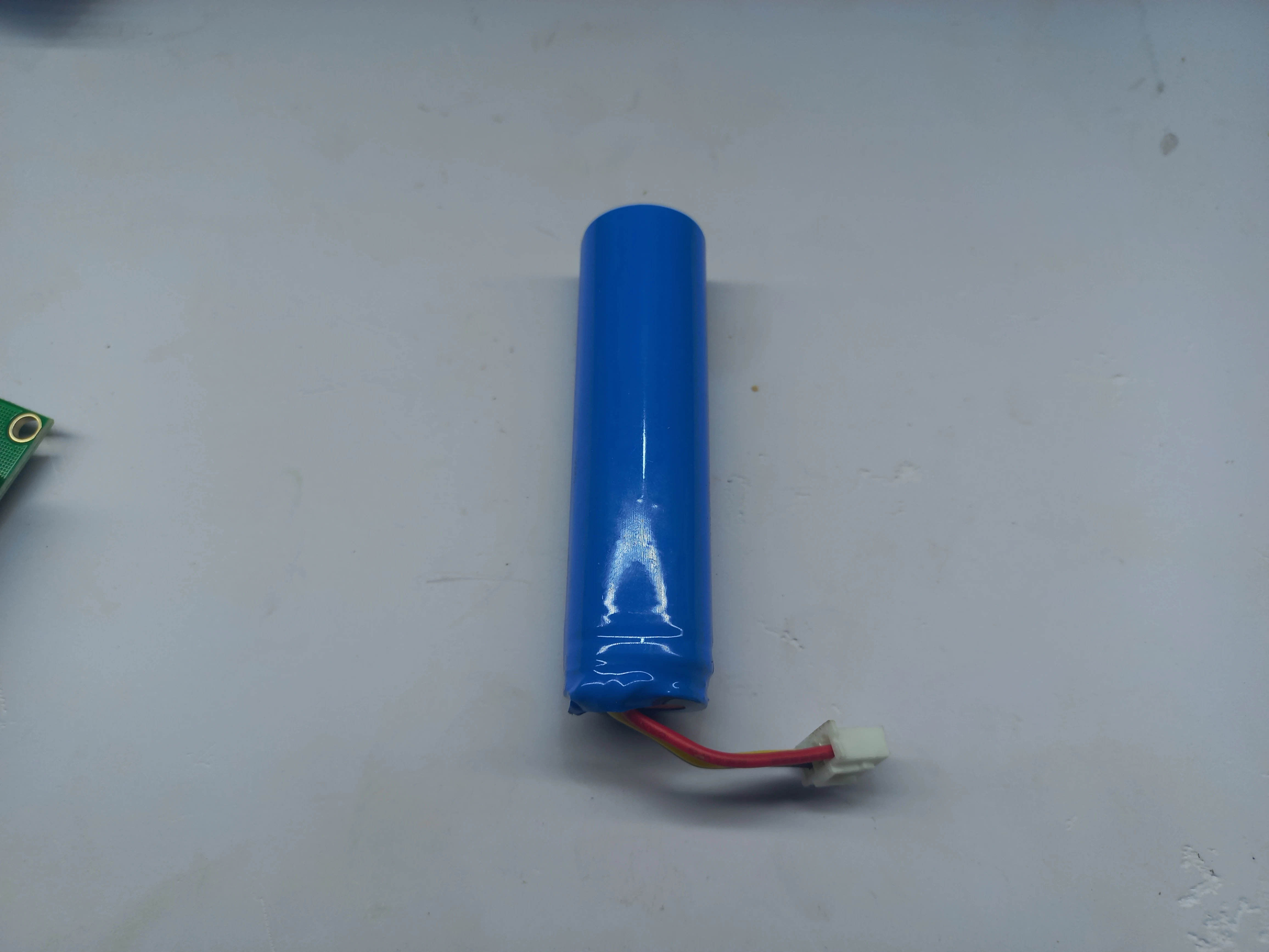
HWE 18650 E6 3200 mAh 3.7 V battery with JST connector: wearable unit power source
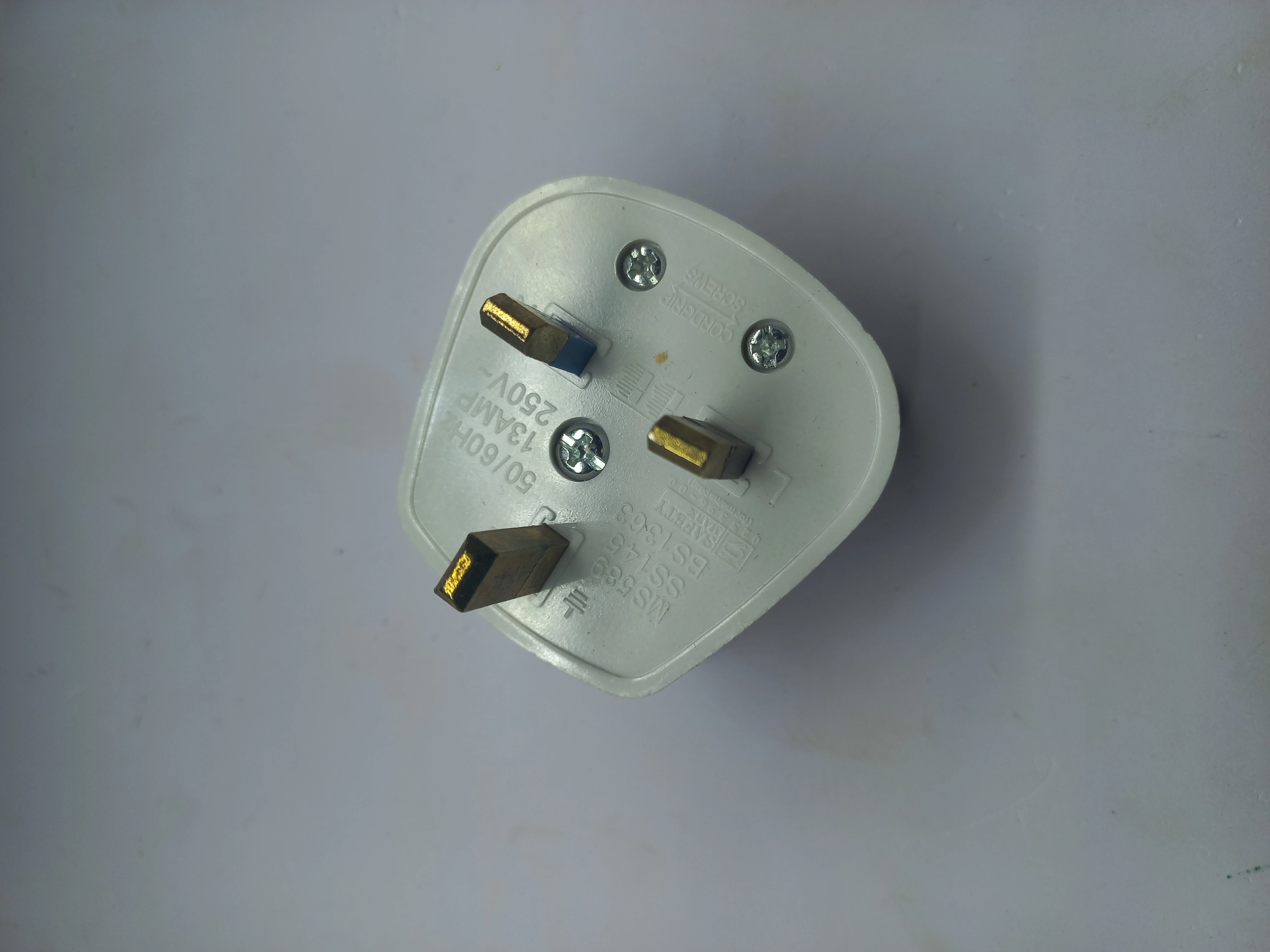
UK BS1363 3-pin mains plug (3 A, 250 V) attached to the BT AC adapter cable for road unit AC input
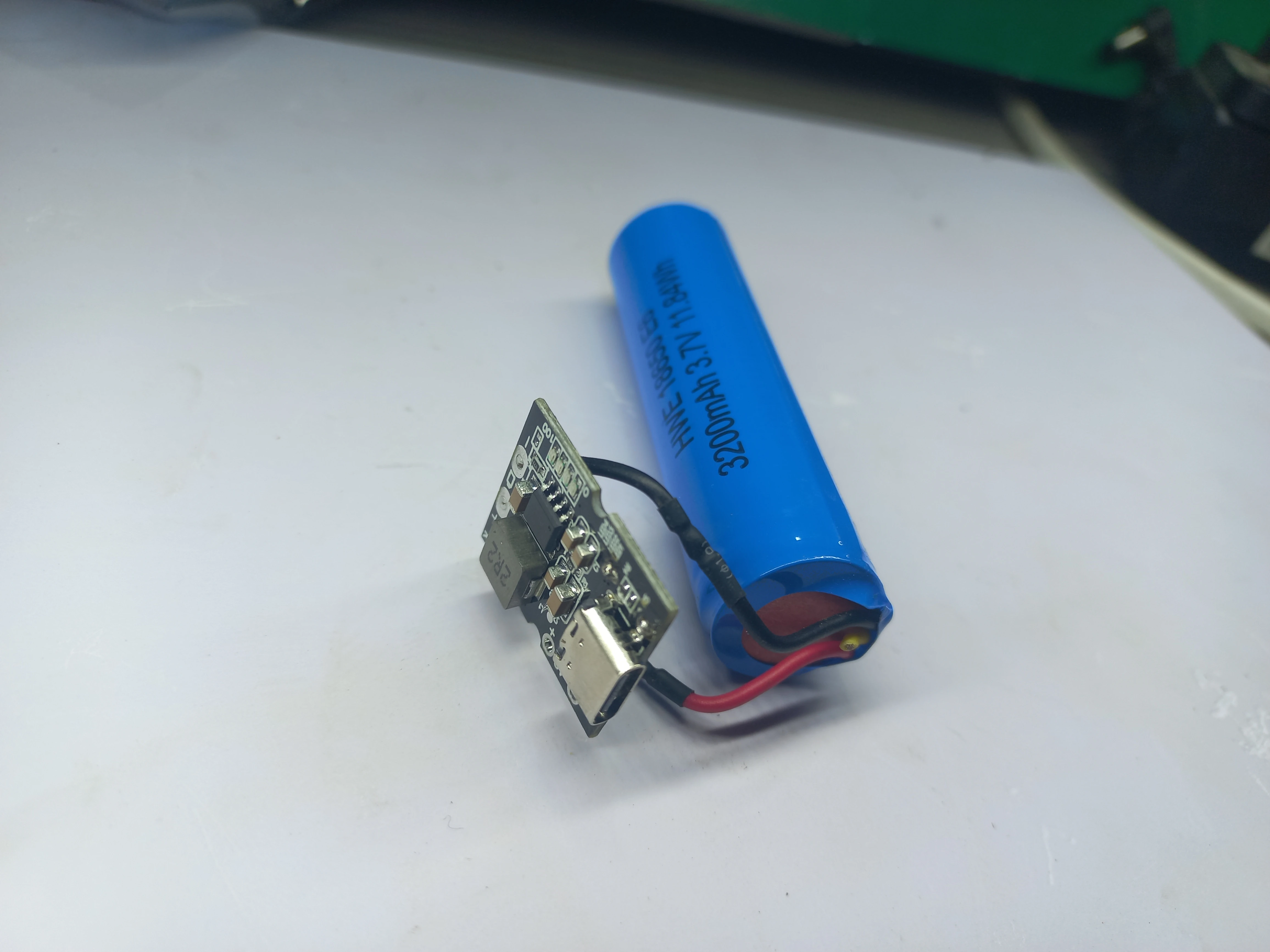
18650 battery wired up to the TP4056 USB-C charging module
Enclosure Fabrication, April 2026
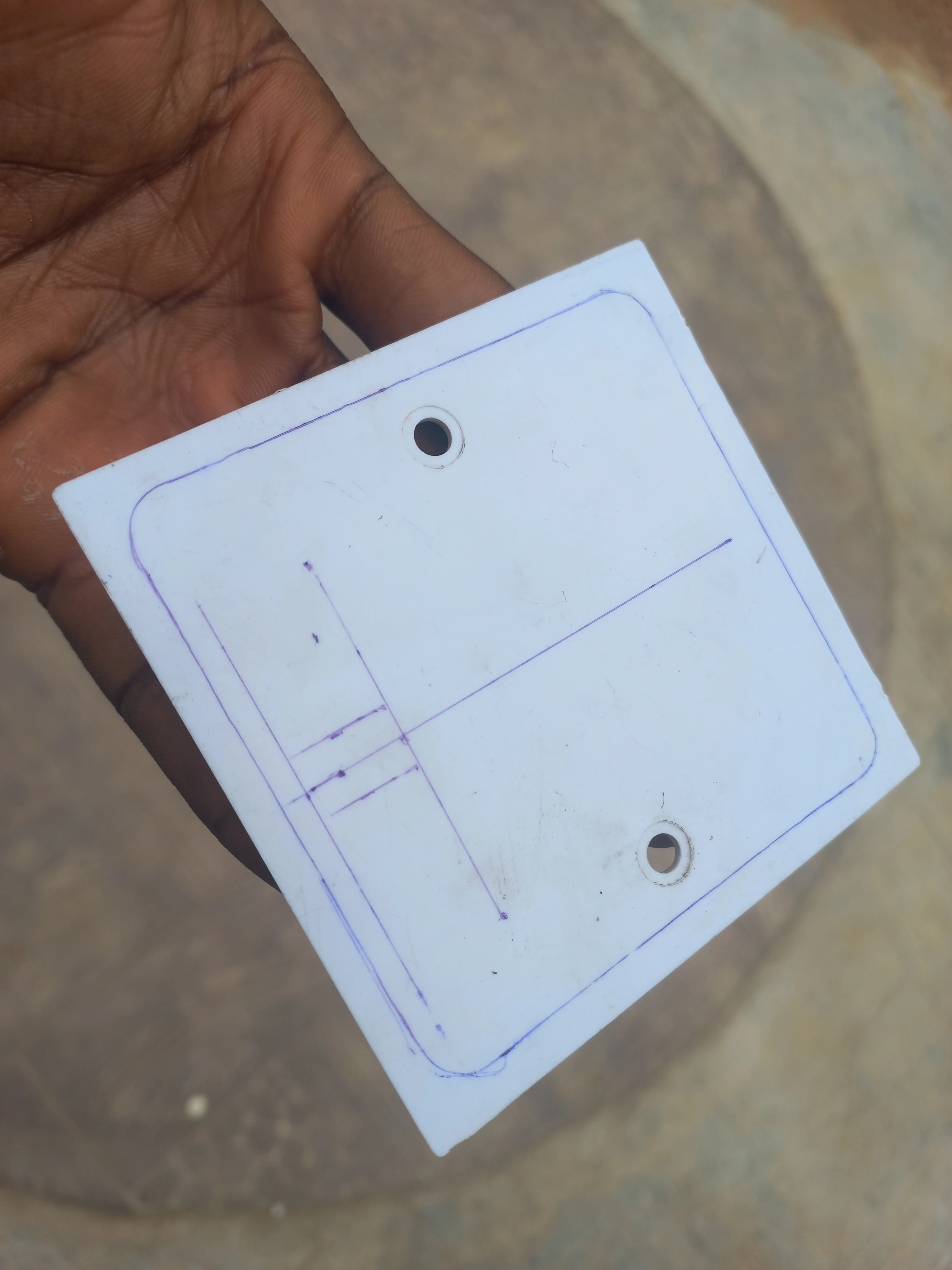
White PVC junction box cover plate with component cutout positions marked in pencil before cutting
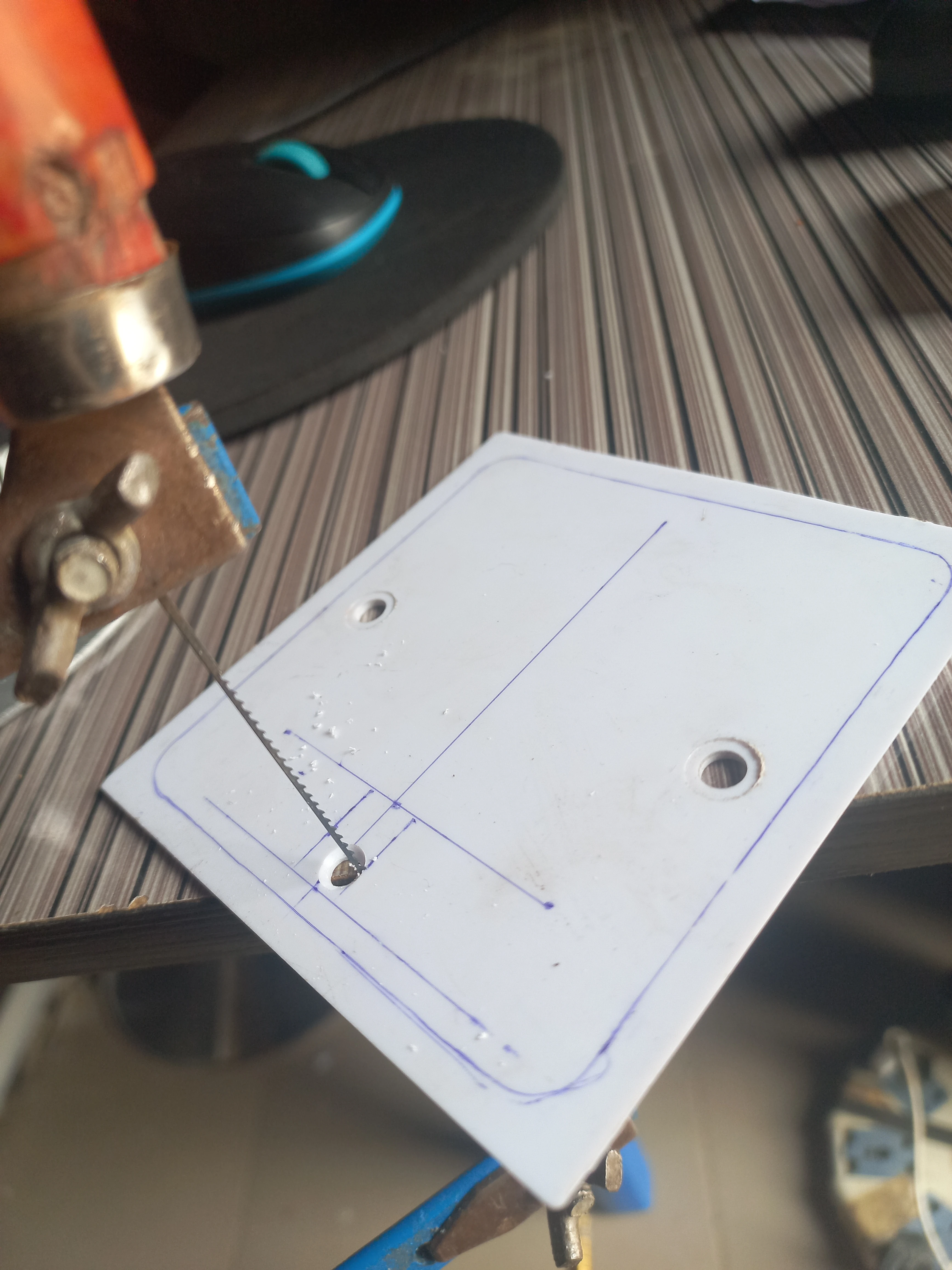
Hacksaw cutting through the PVC enclosure panel to create a component aperture
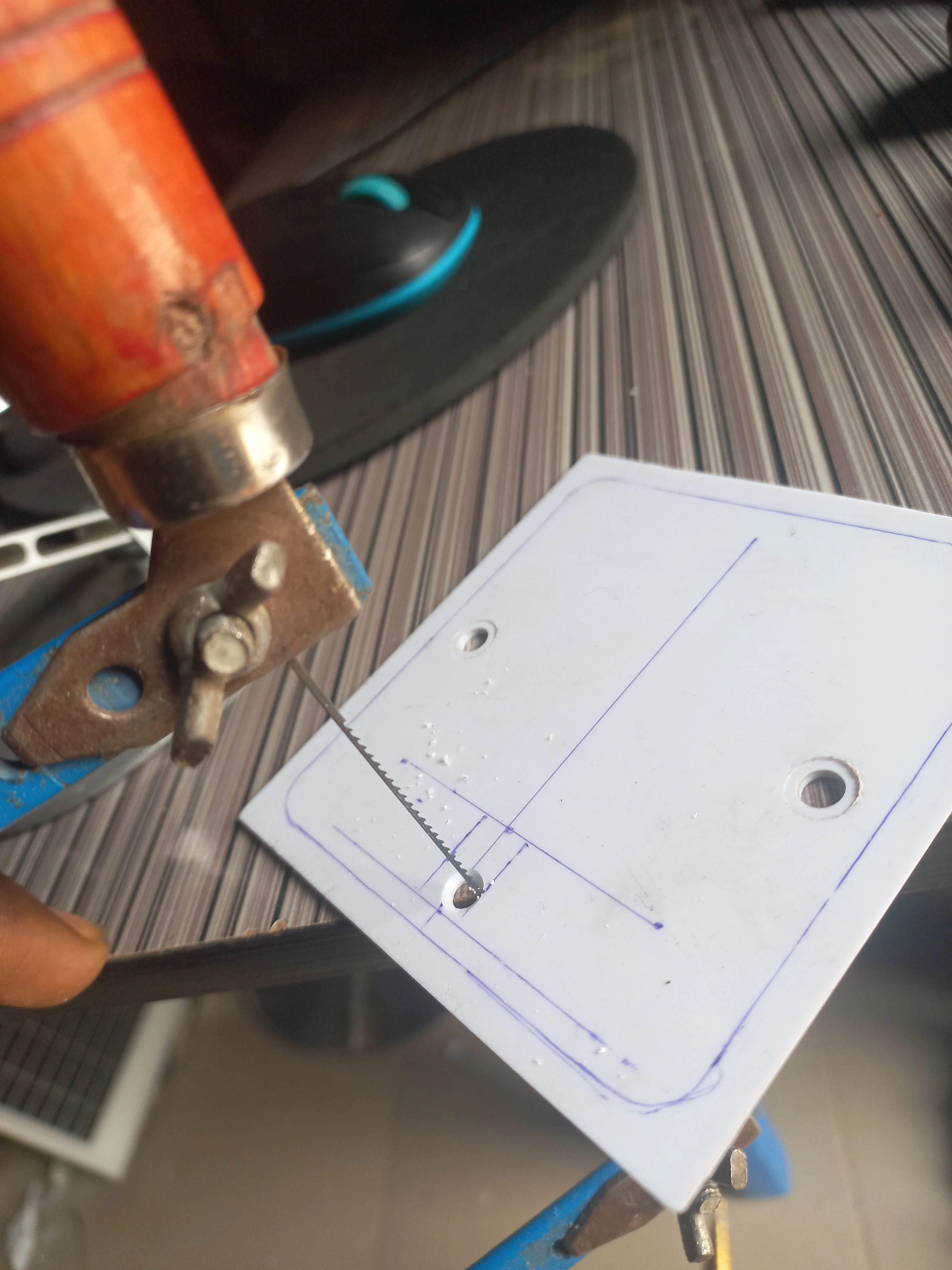
Angled view of the enclosure panel cutting operation showing the cut in progress
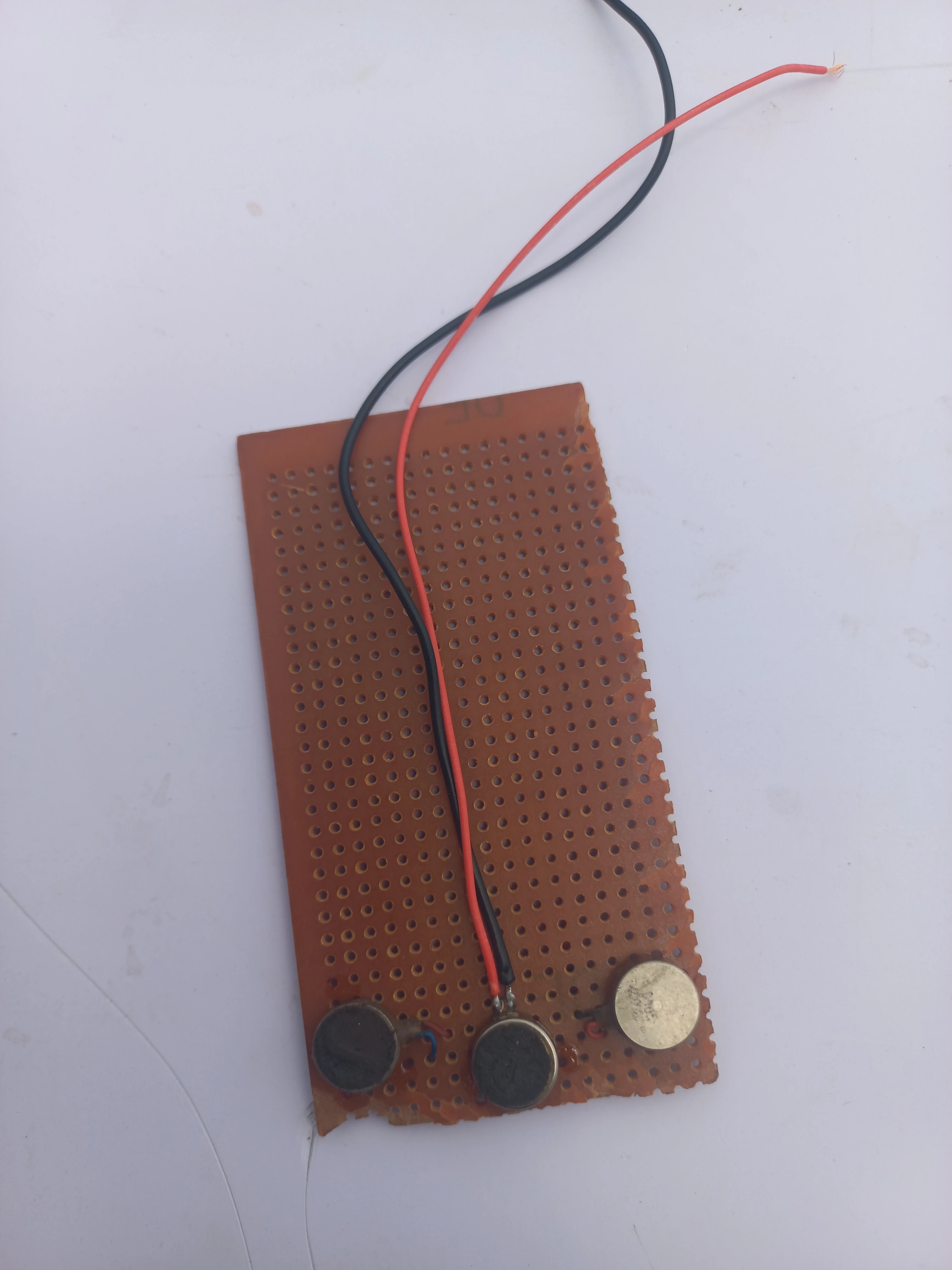
Coin vibration motor soldered onto a small perfboard sub-assembly for the wearable unit
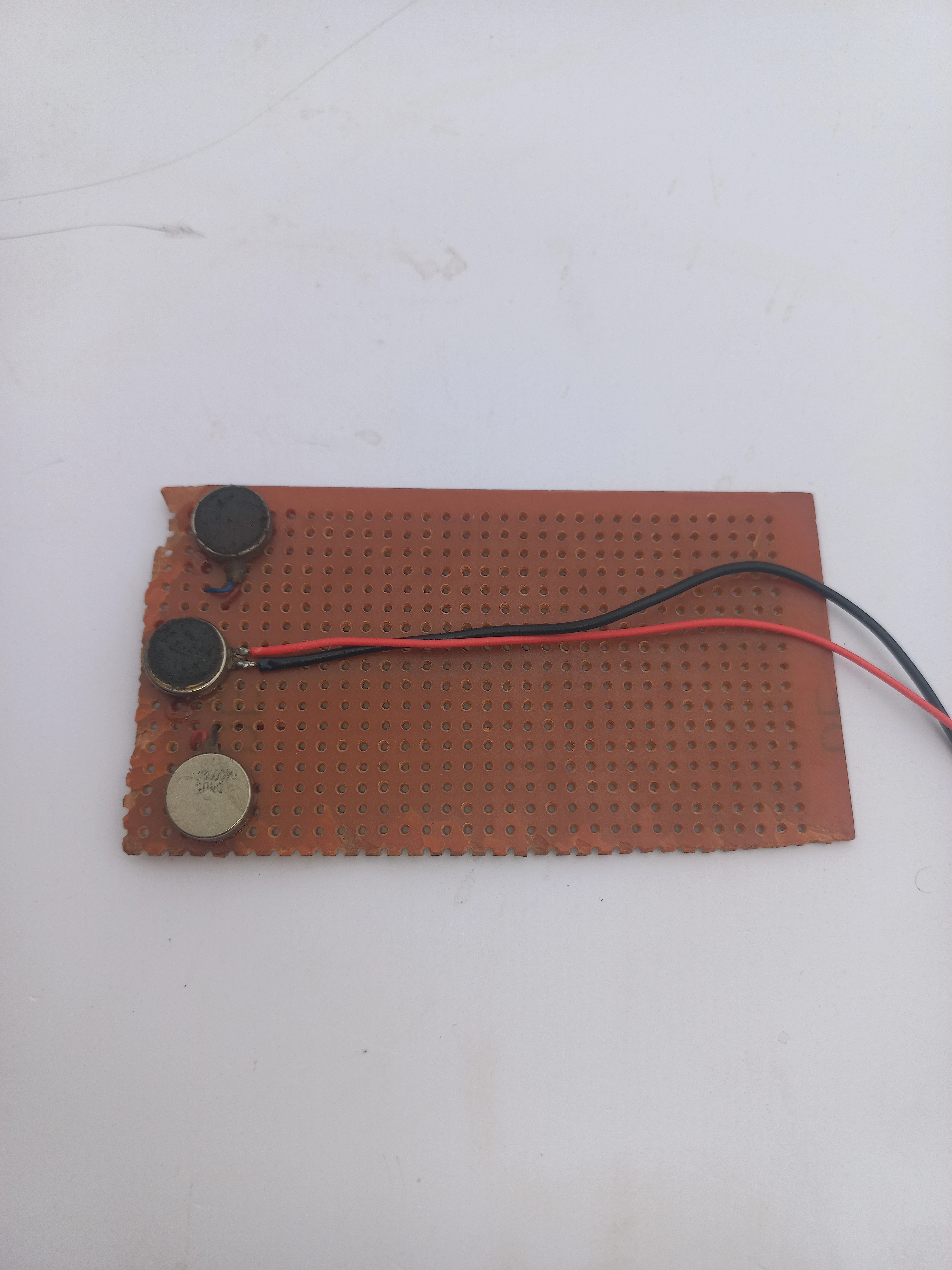
Haptic motor perfboard laid flat showing the copper side with solder joints
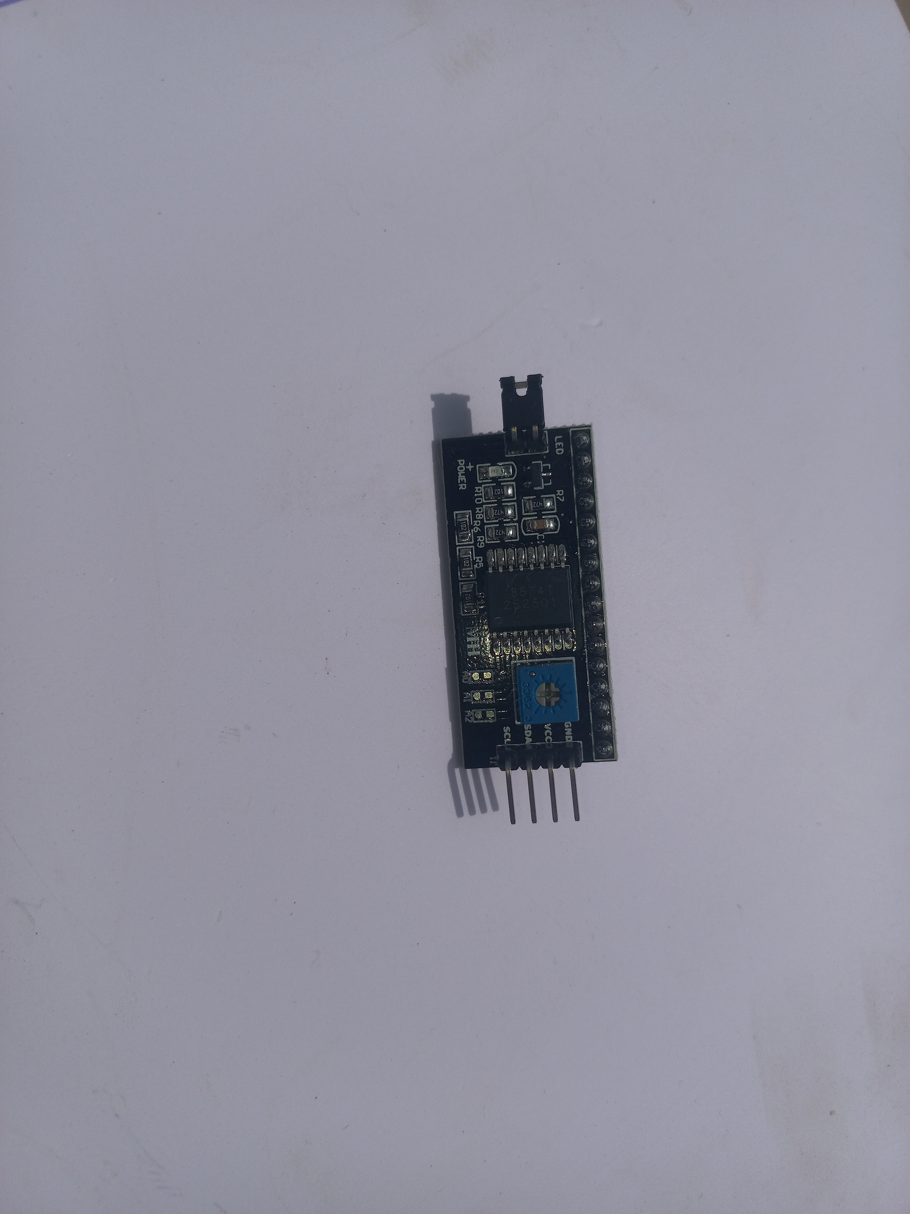
PCF8574-based I2C backpack module mounted on the 20x4 LCD for the road unit
System Assembly, April 2026
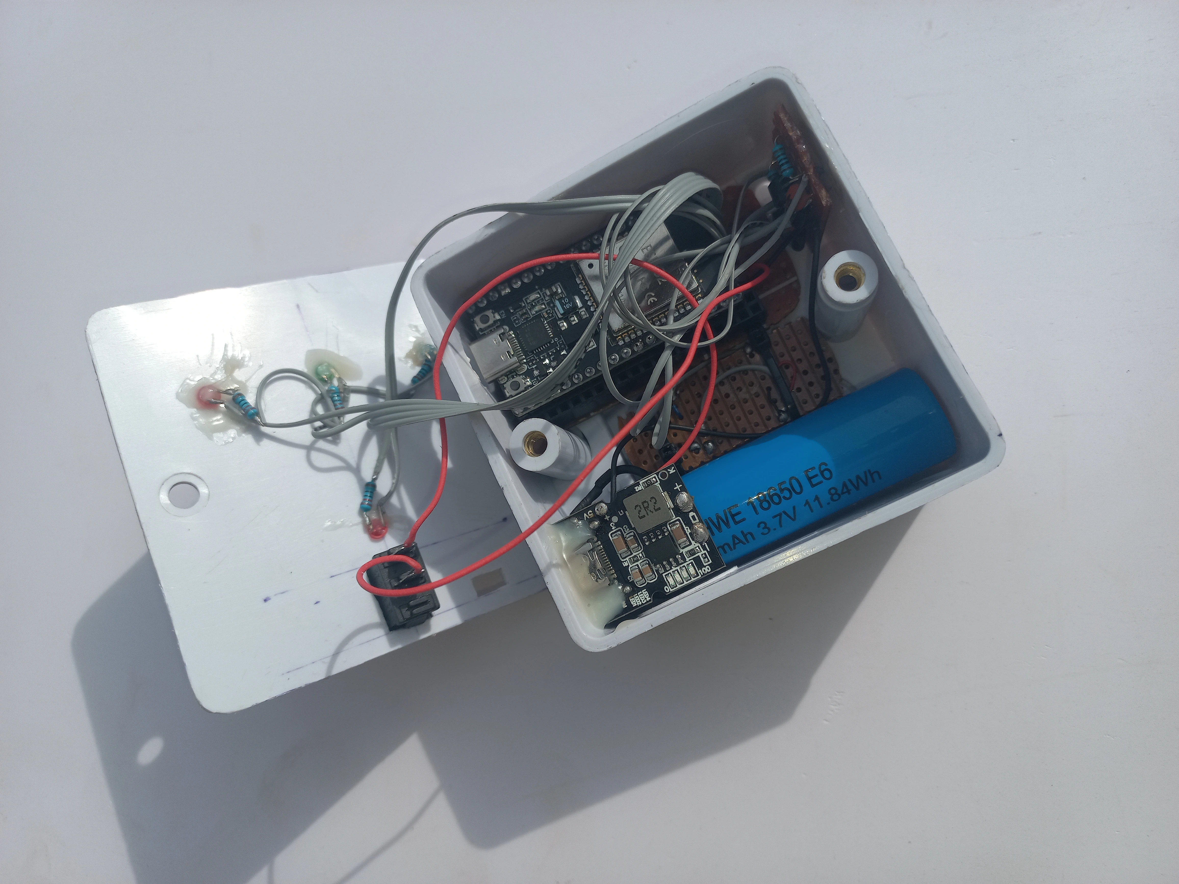
Wearable unit enclosure open showing the ESP32 board, TP4056 charger module, and 18650 battery inside
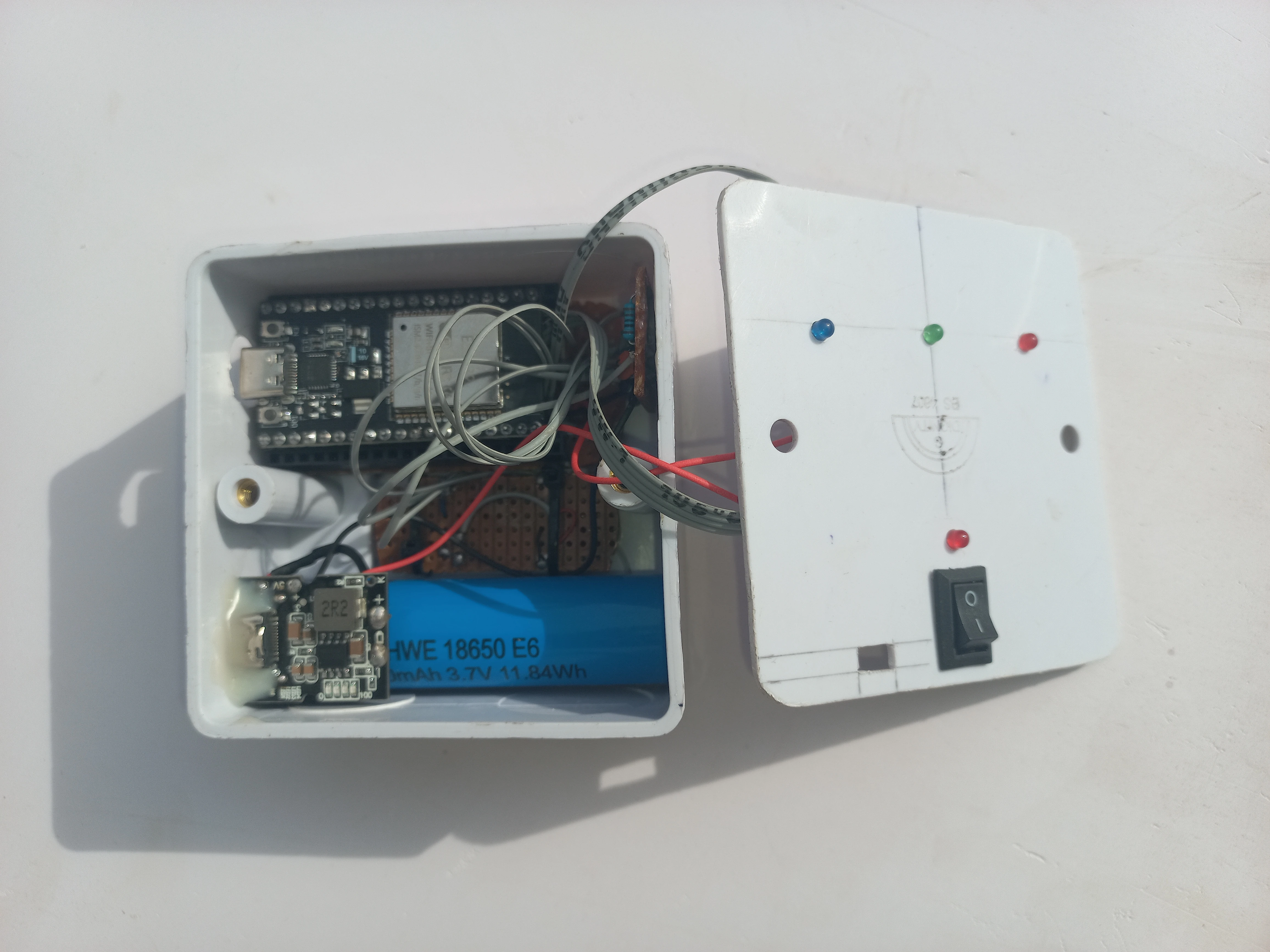
Wearable unit with front panel positioned, showing the LED cutout holes in the enclosure lid
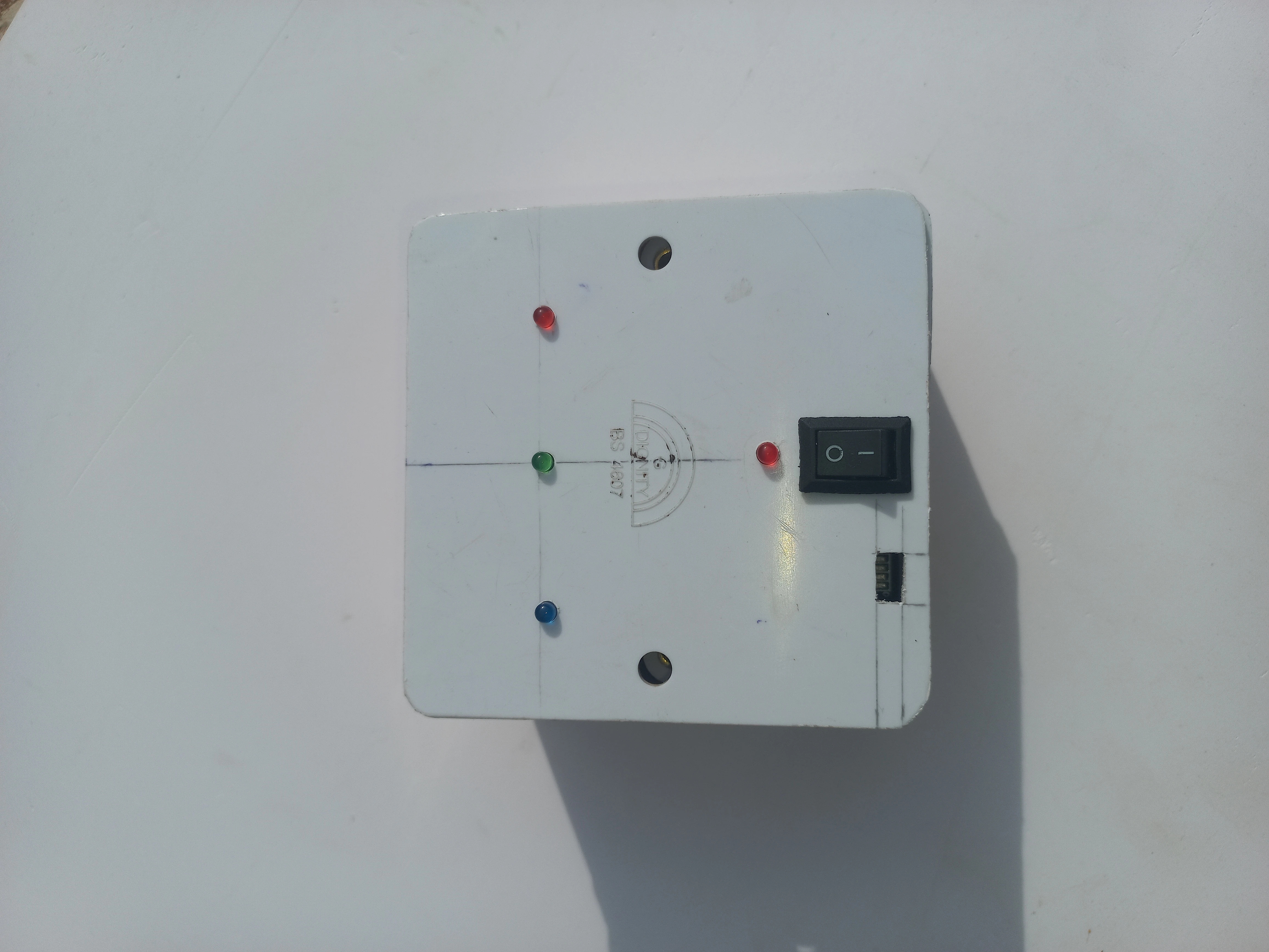
Wearable unit front panel with red, green, and blue LED indicators installed in their cutouts
Road model under construction with traffic light post assemblies being fitted at the crossroads corners
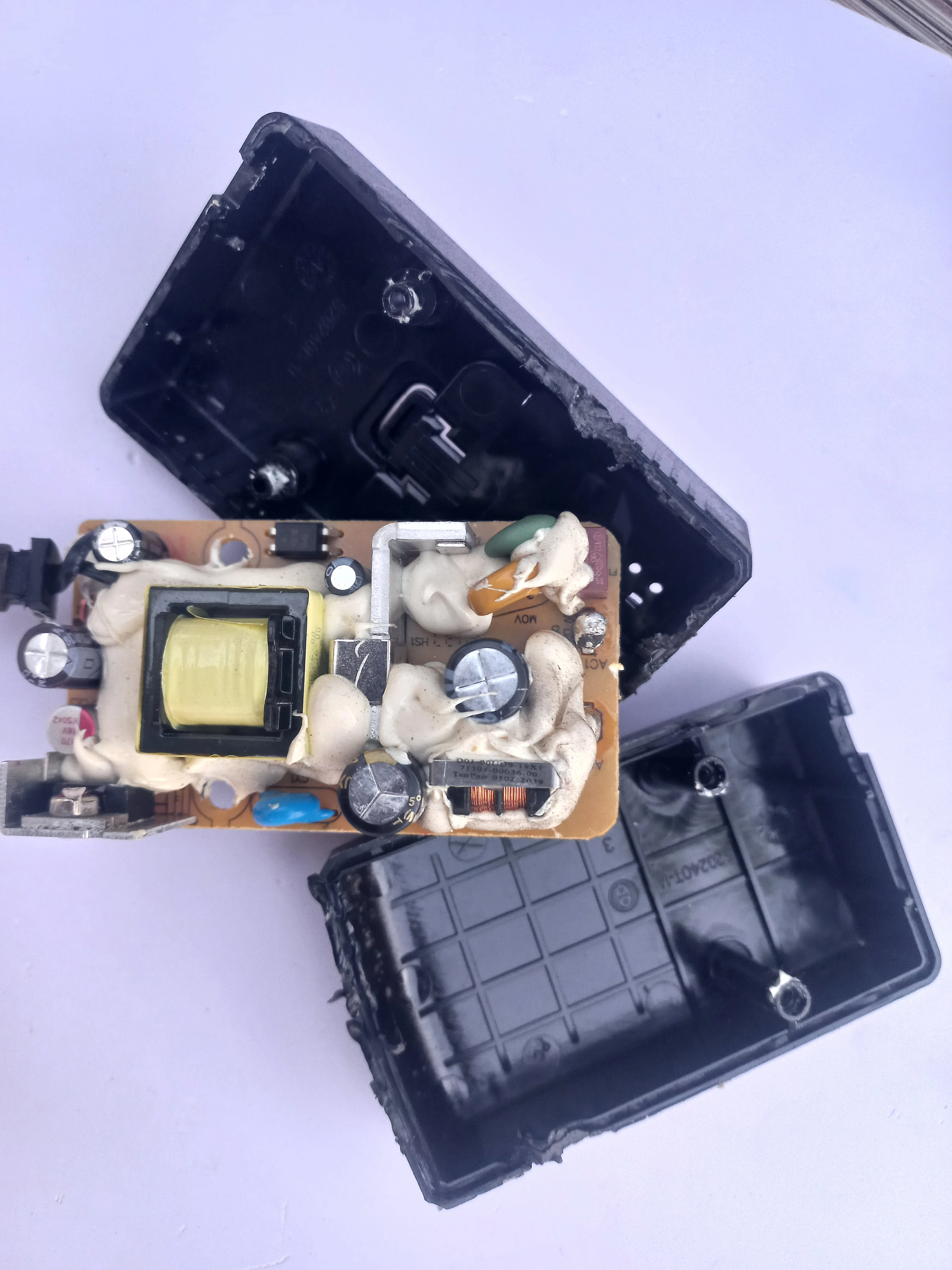
BT AC adapter opened and disassembled, showing the internal switching PCB and transformer
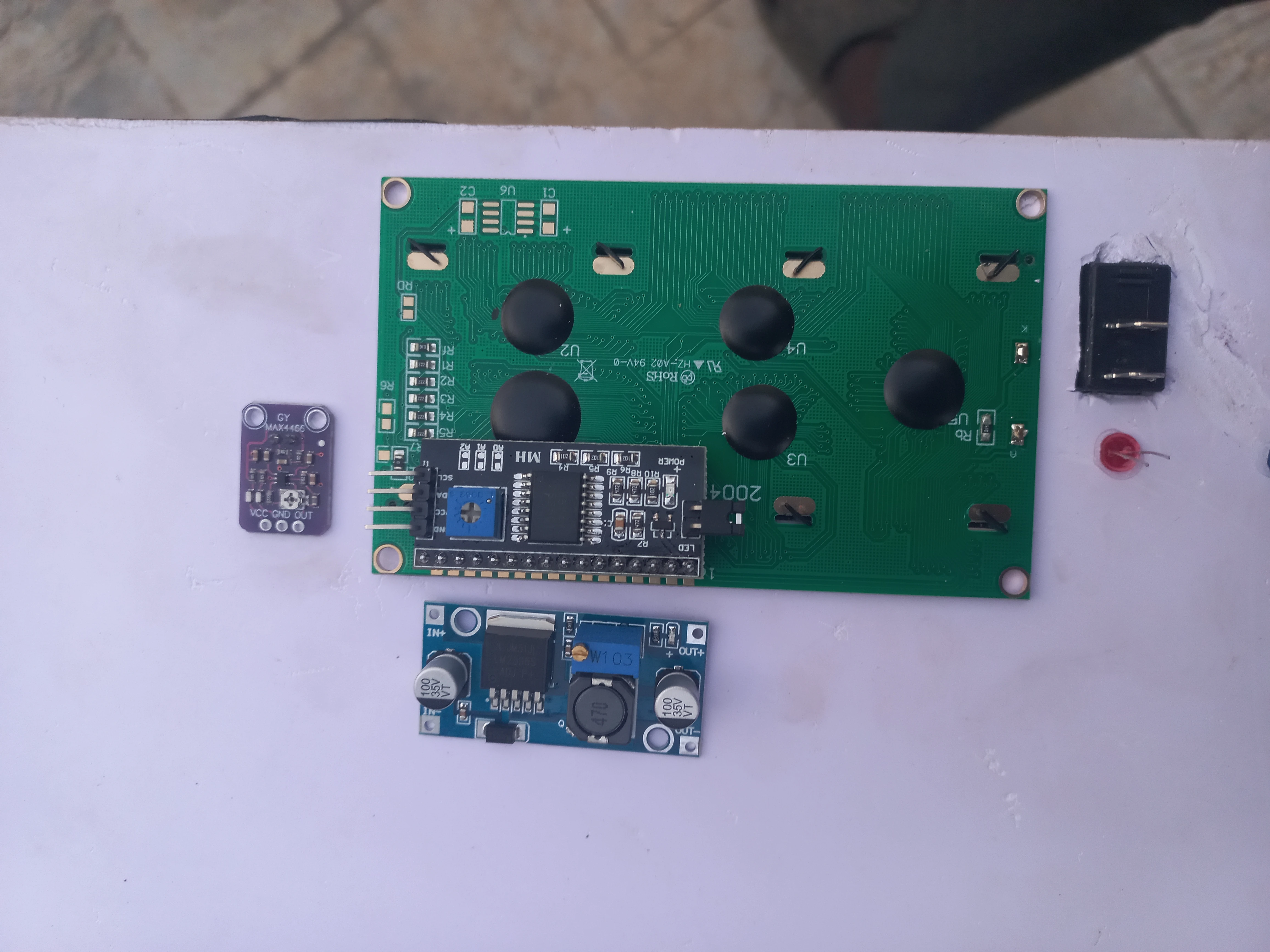
Road unit components arranged before integration: ESP32, 20x4 LCD, MAX4466 microphone module, LM2596 buck converter, and wiring
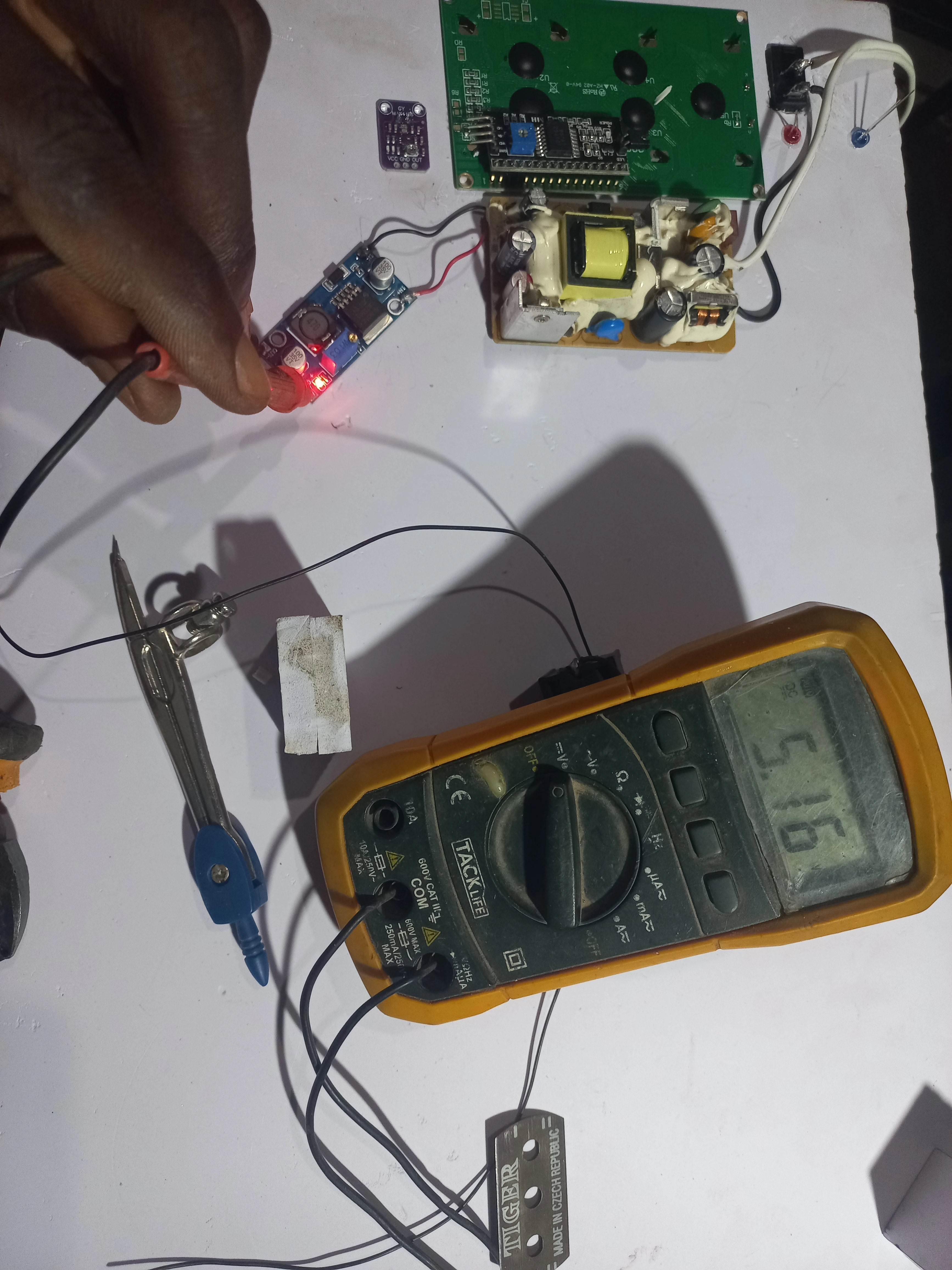
Multimeter probes on LM2596 output terminals confirming 5.16 V regulated supply for the road unit logic rail
Completed System and Live Demonstration, May 2026

Developer holding the completed wearable unit showing the front panel with LED indicators
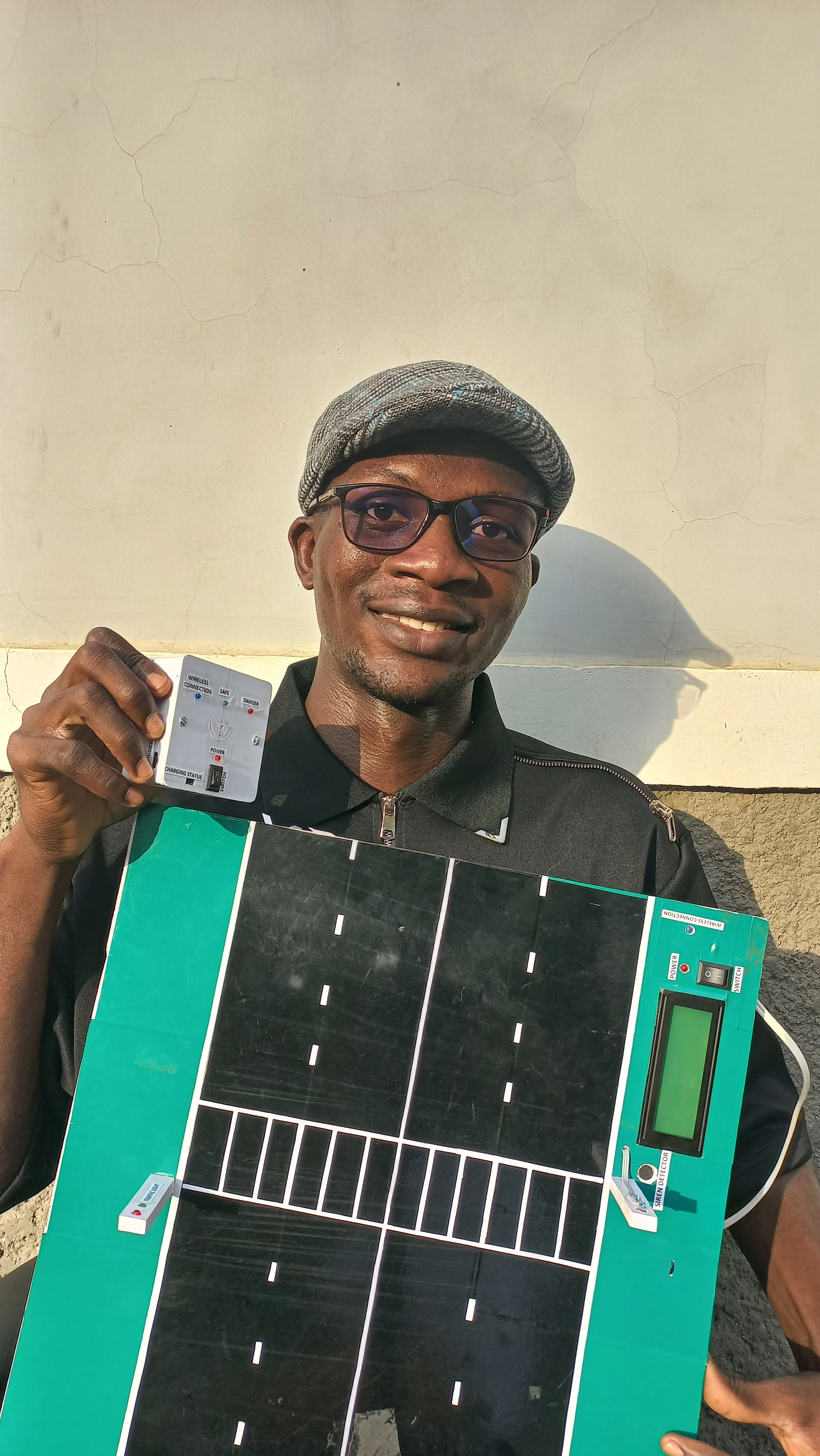
Developer smiling while holding both completed units: wearable unit in right hand, road model in left hand
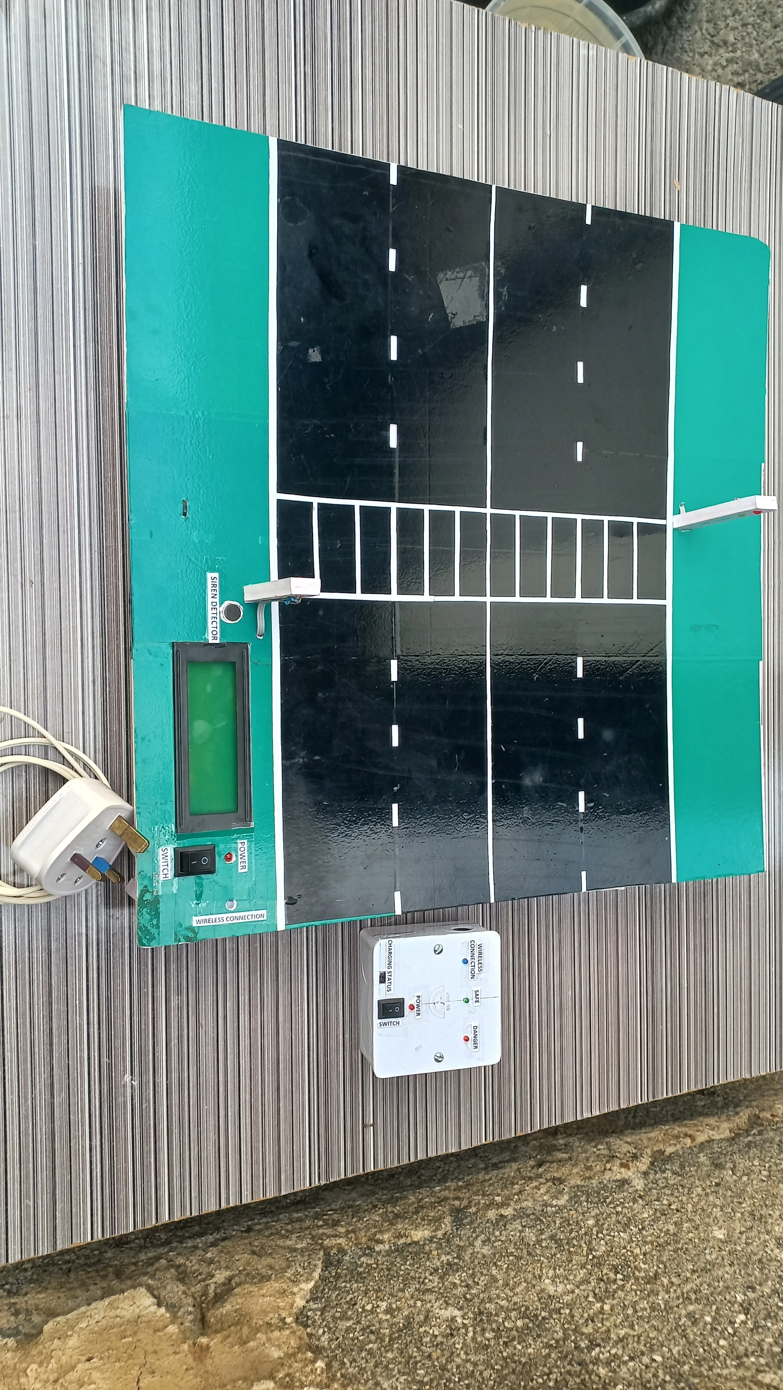
Overhead view of the completed road model: four-arm crossroads with traffic lights at each corner, green grass areas, and pedestrian crossing
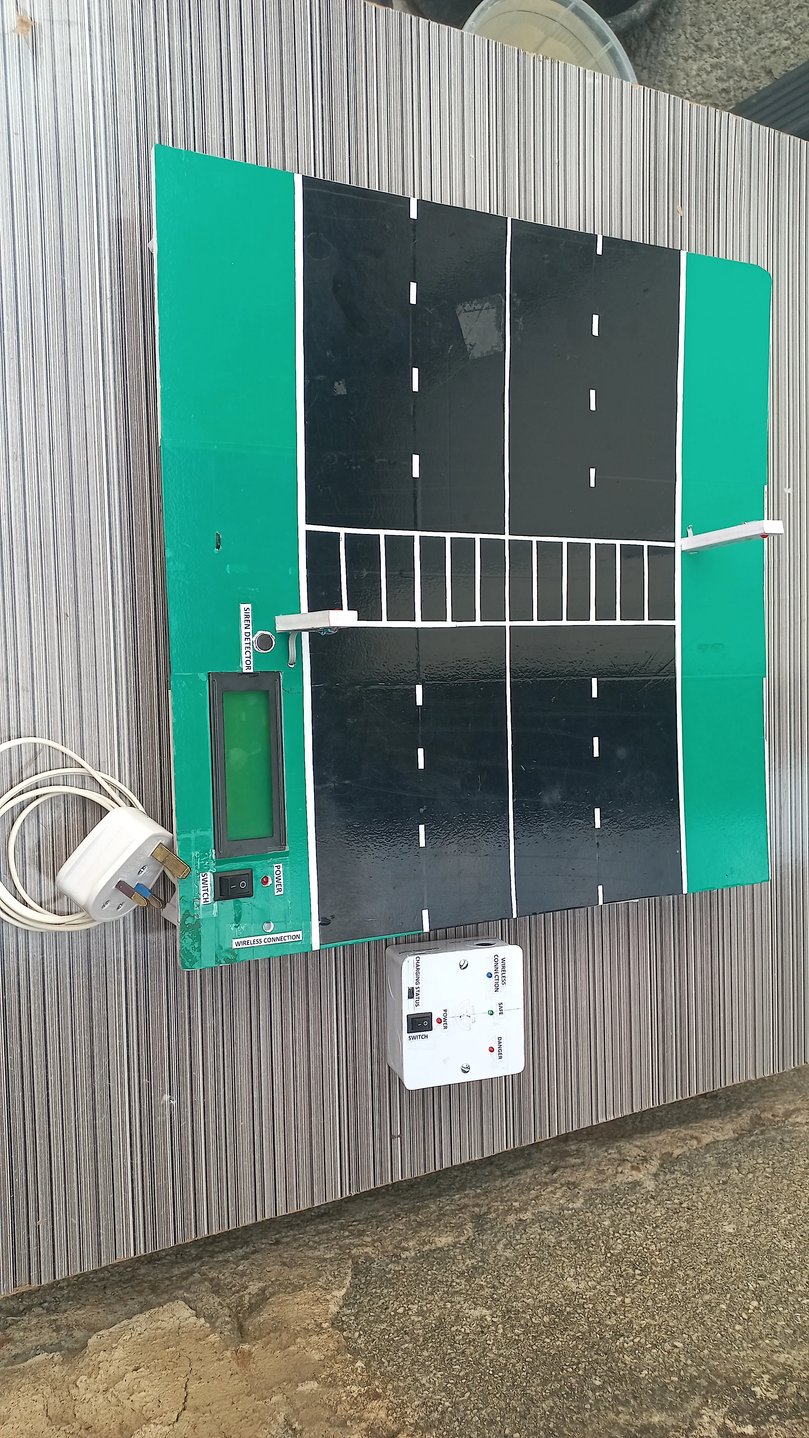
Perspective view of the completed road model showing the elevated structure, traffic light posts, and road markings
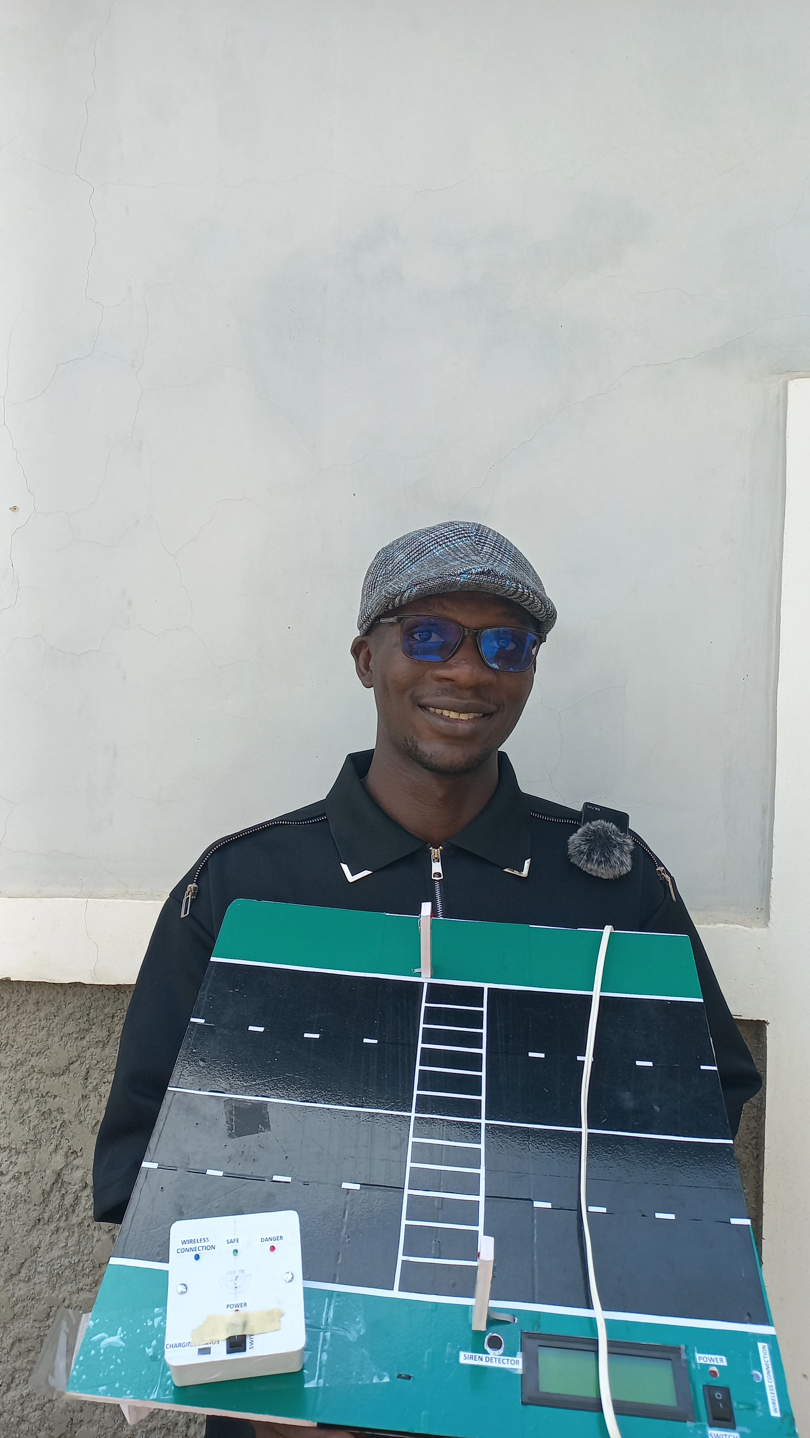
Developer wearing sunglasses, presenting the completed road model at the demonstration
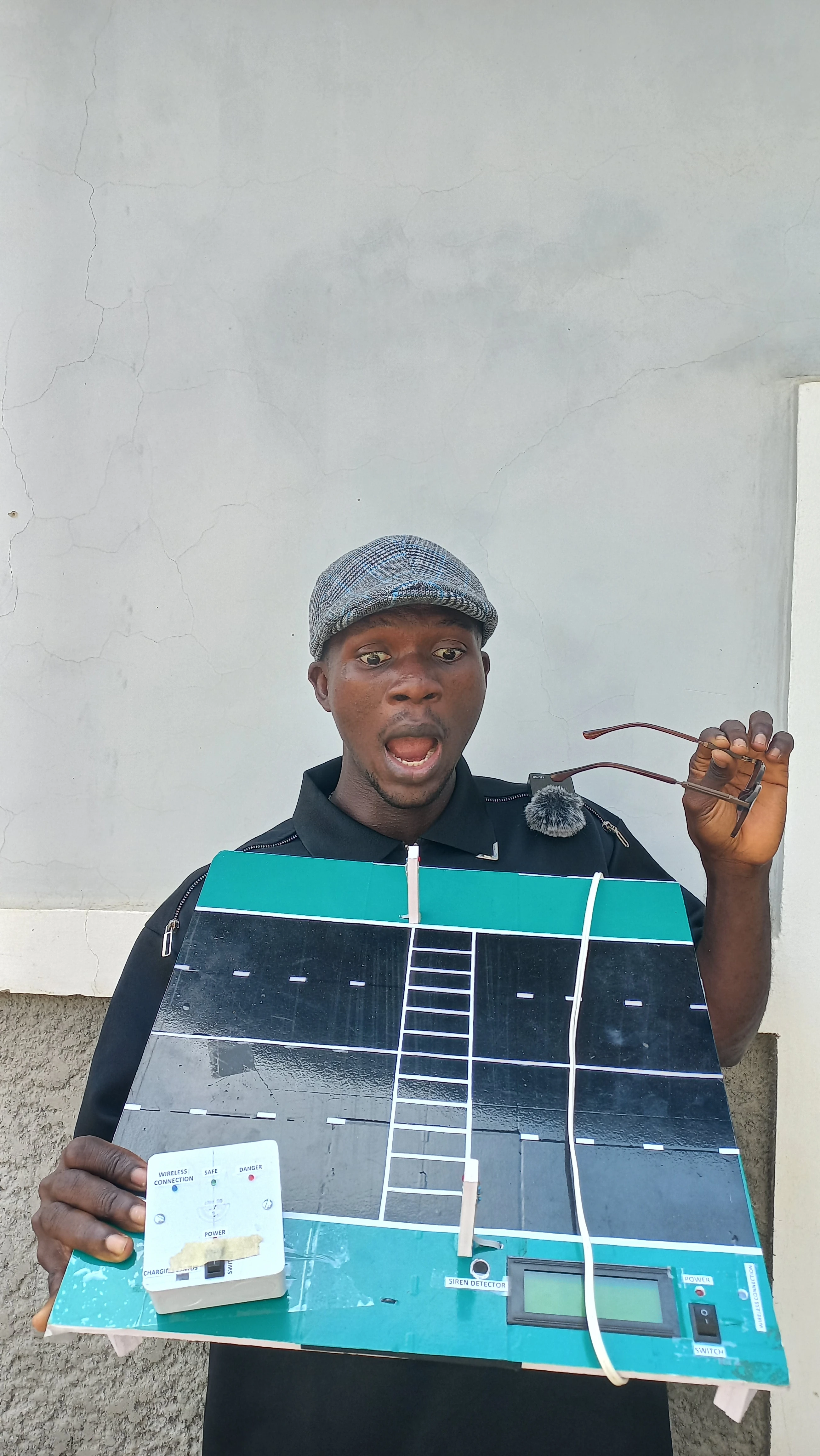
Developer smiling while displaying the completed road model
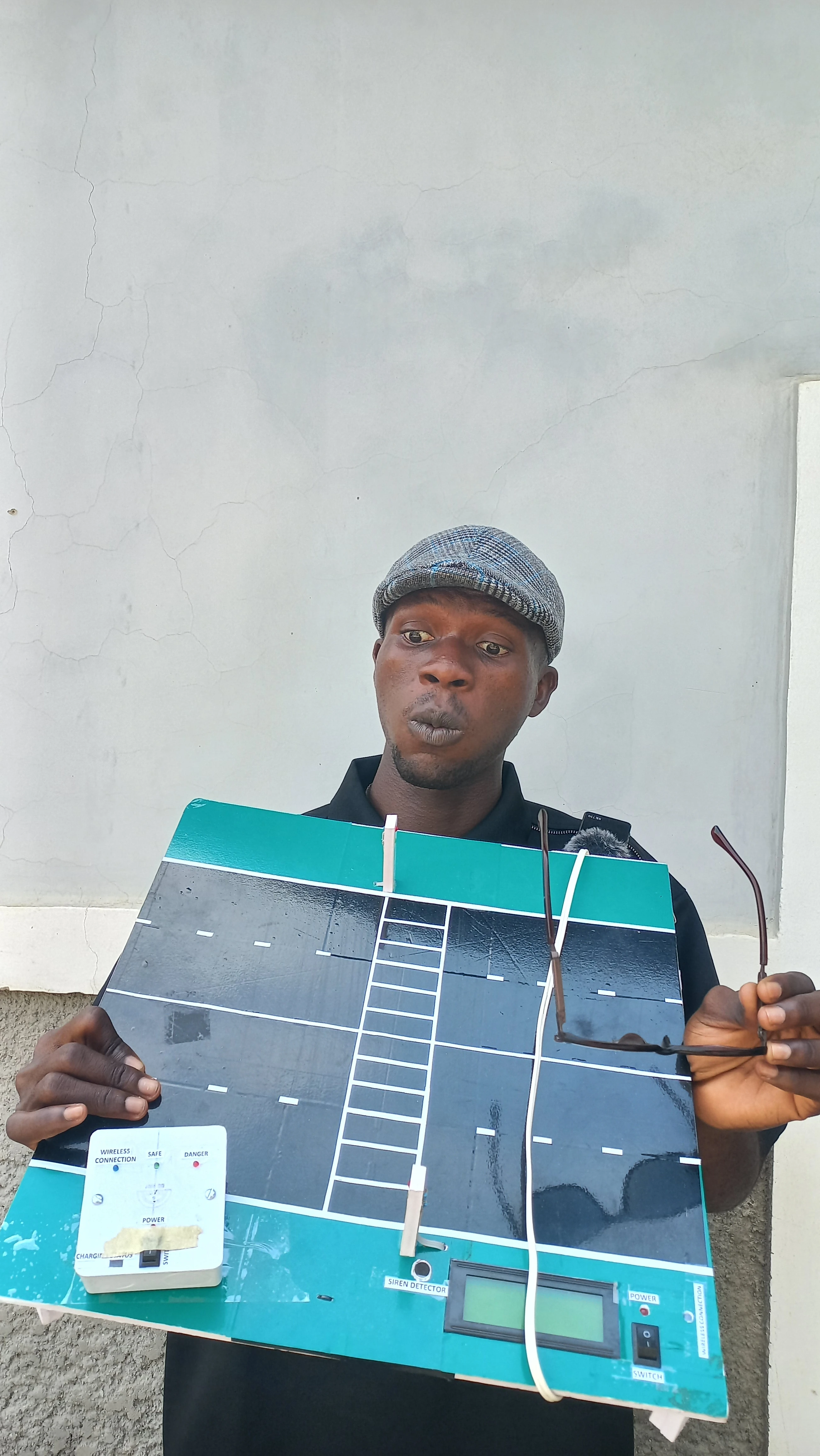
Developer holding the road model with a neutral expression for a clear view of the complete structure

Developer pointing at the traffic light on the road model while holding the wearable unit: complete system demonstration
Challenges & Solutions
-
Challenge: Distinguishing genuine emergency sirens from ambient road noise
(vehicle engines, wind, music) on the microphone input.
Solution: Applied FFT spectral analysis to isolate the 400–2500 Hz
frequency range characteristic of ambulance and fire truck sirens. Threshold tuning reduced
false positives from broadband noise.
-
Challenge: Designing a haptic vocabulary that is intuitive without training
and distinct enough to avoid confusion between states.
Solution: Three patterns with clearly different rhythms: a long continuous
burst for danger (unmistakably "stop"), a rhythmic triple-burst for safe crossing, and a
fast urgent pulse for emergency. Rhythm length and density are the differentiators.
-
Challenge: Detecting when the wearable user has moved out of ESP-NOW range
without a reliable disconnect event from the protocol.
Solution: Implemented a 2-second heartbeat ping from wearable to road unit.
If the road unit misses heartbeats beyond a timeout threshold, it flags the wearable as
disconnected and updates the LCD status field accordingly.
-
Challenge: Supplying stable 5 V to the road unit ESP32 and LCD from the
12 V AC adapter without excessive heat dissipation from a linear regulator.
Solution: Used an LM2596 adjustable buck converter (switching regulator)
trimmed to 5.16 V output. Verified with a multimeter before connecting the ESP32 to avoid
overvoltage damage.
Results & Impact
- Functional haptic communication: All three vibration patterns (danger, walk,
emergency) were confirmed working during live testing and demonstration.
- Reliable wireless link: ESP-NOW peer-to-peer communication operated without
a router or internet connection, demonstrating the system's infrastructure-independence.
- Accurate siren detection: FFT-based analysis on the MAX4466 microphone
detected the simulated emergency frequency sweep and triggered the emergency override
correctly in tests.
- Heartbeat safety mechanism: Connection-loss detection via the 2-second
heartbeat ping successfully flagged when the wearable moved beyond ESP-NOW range.
- Accessibility impact: The system demonstrates a low-cost, infrastructure-
independent solution for giving visually and hearing-impaired pedestrians real-time road
crossing information without relying on audible signals or visual displays.