Touchless Appliance Control using APDS9960 Gesture Sensor, NRF24L01 2.4GHz RF Link, SH1106 OLED Transmitter, 20x4 LCD Receiver, and 4-Channel Relay Load Panel
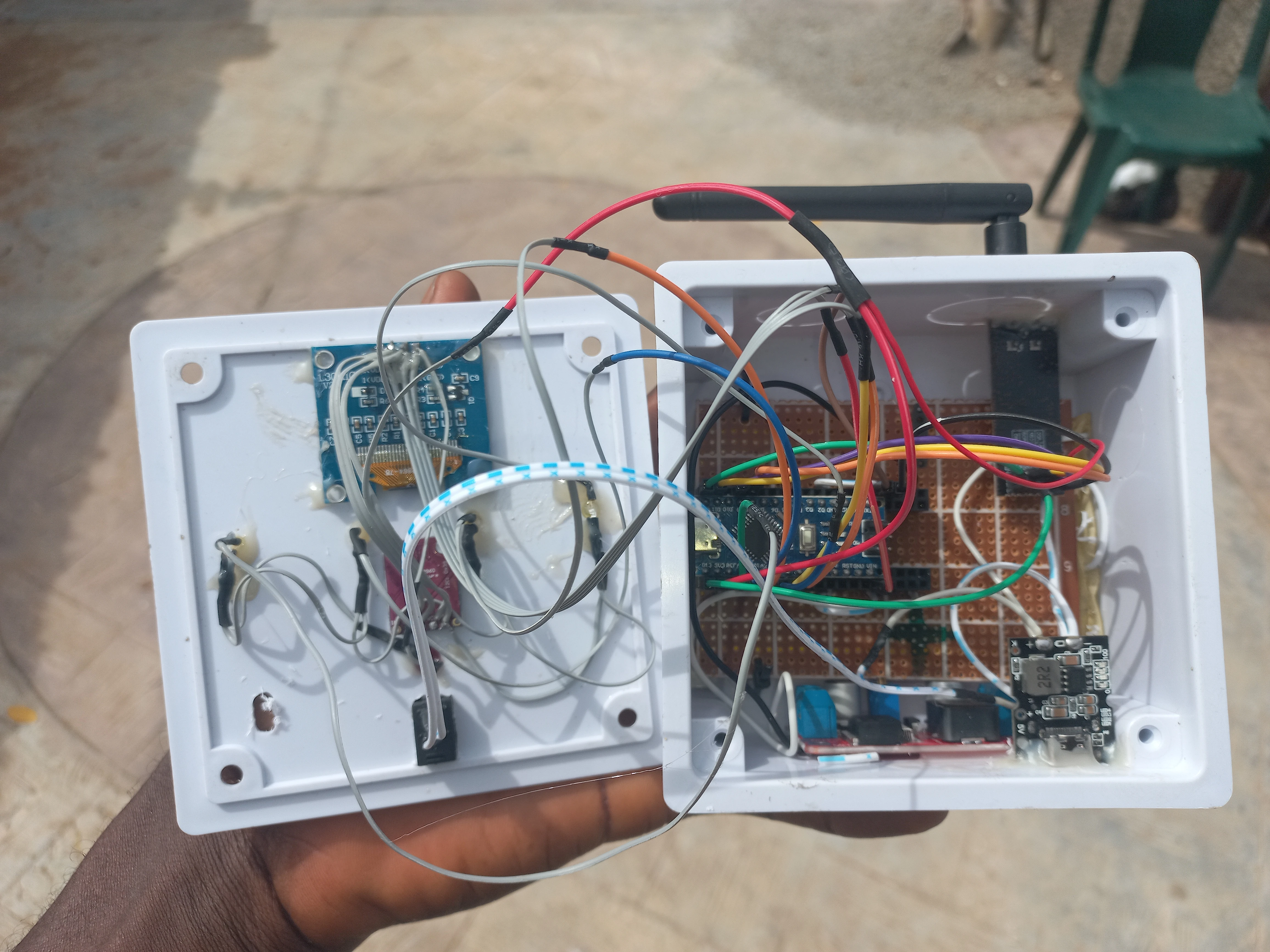
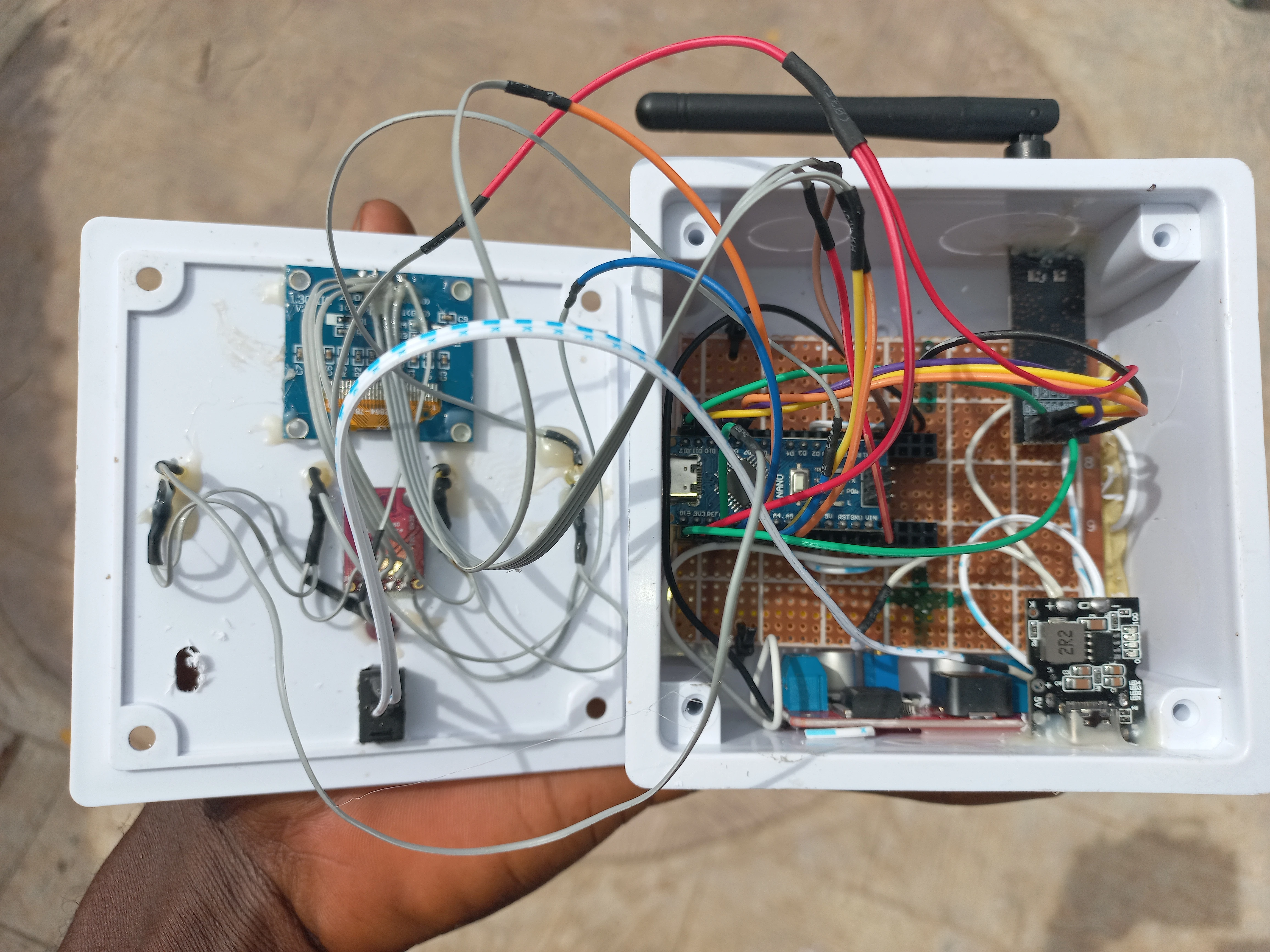
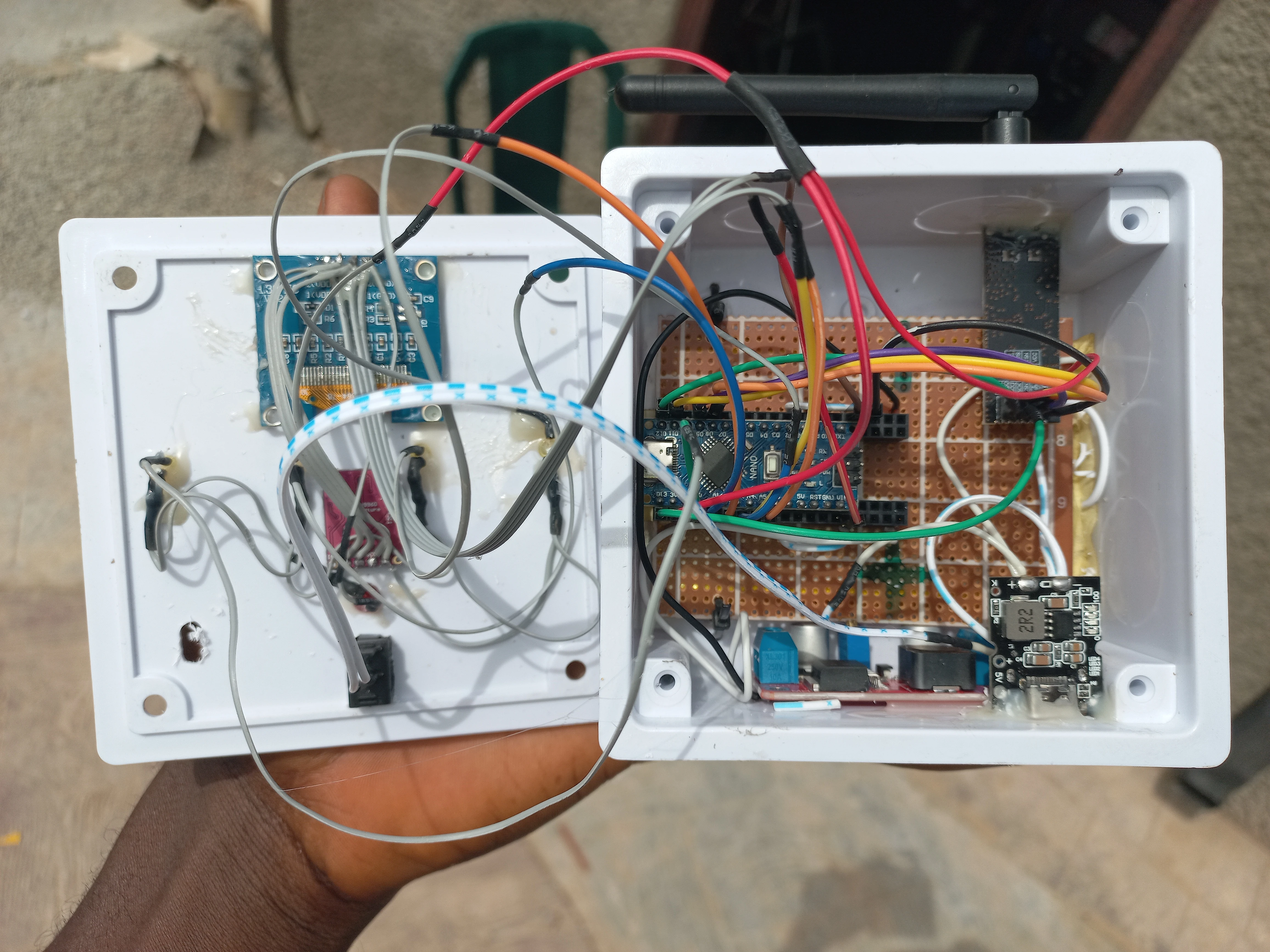
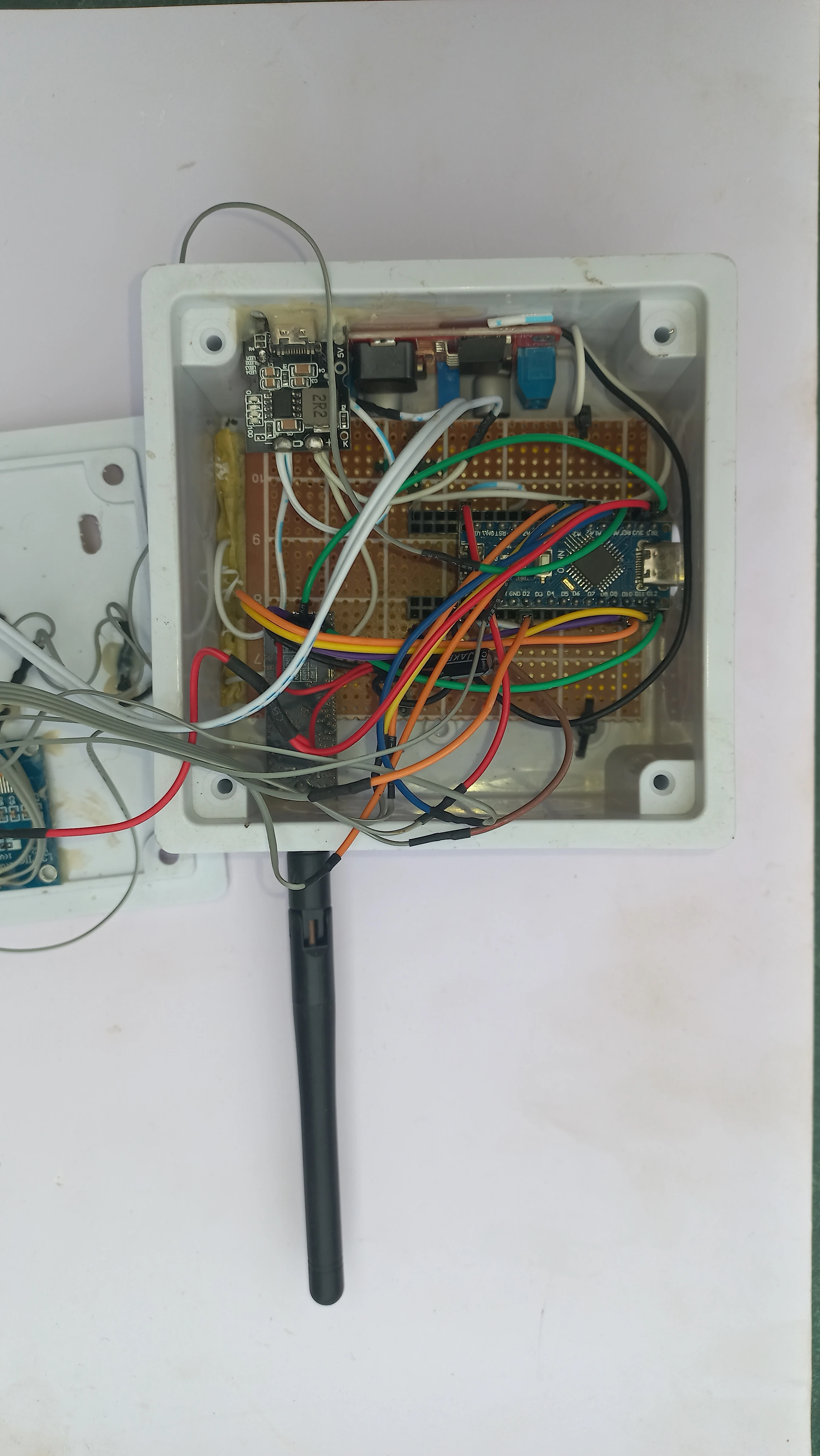
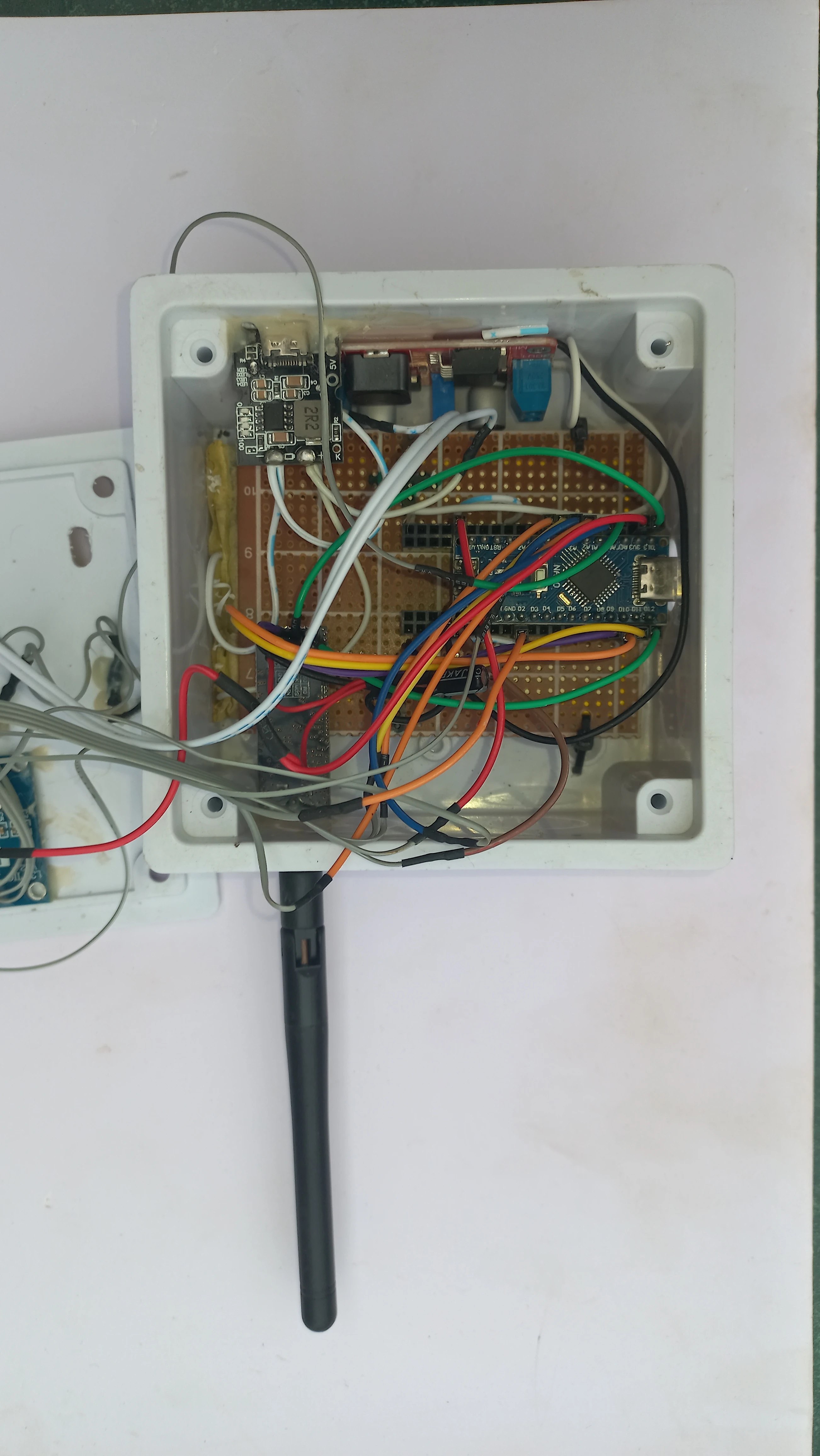
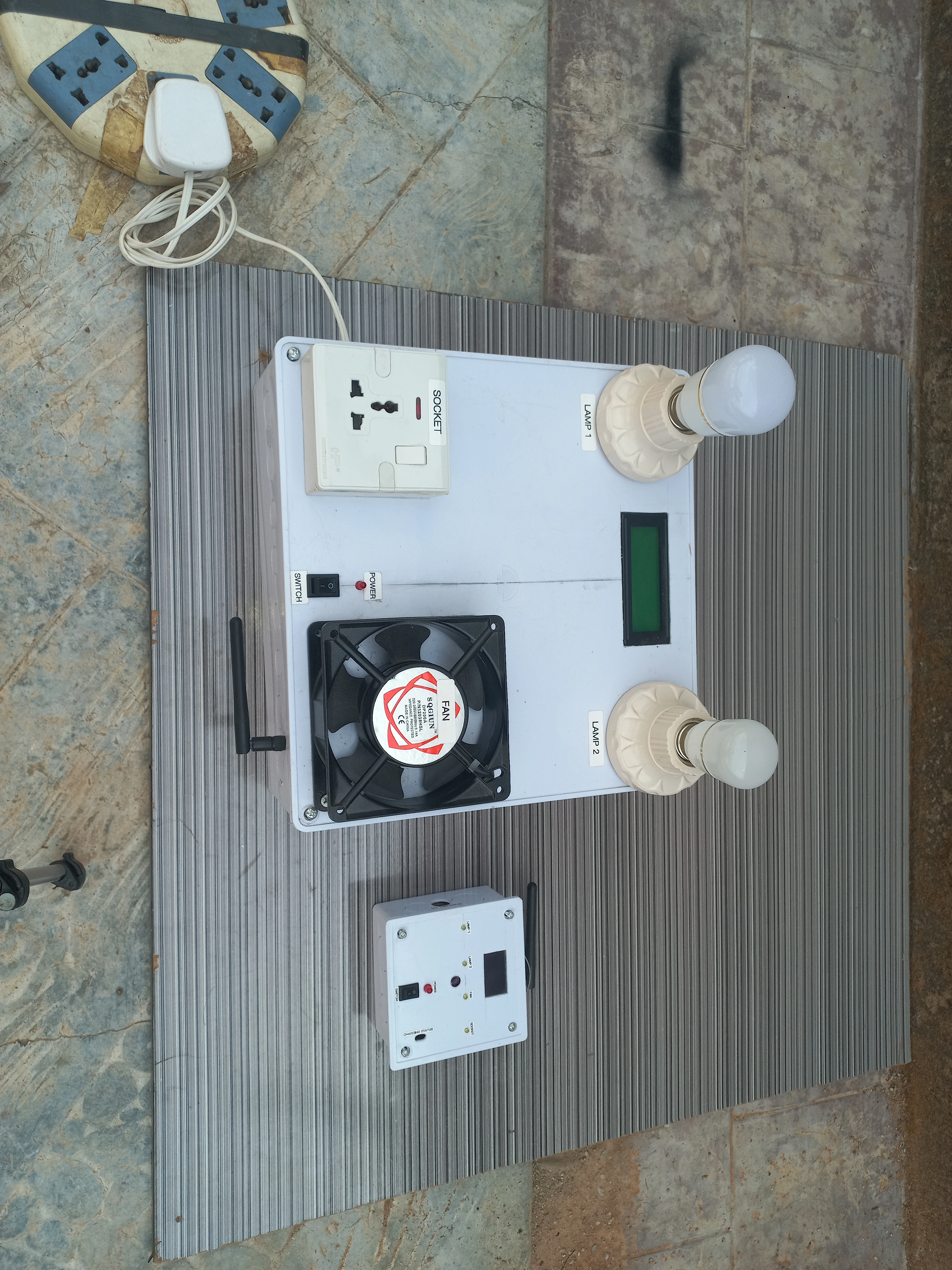
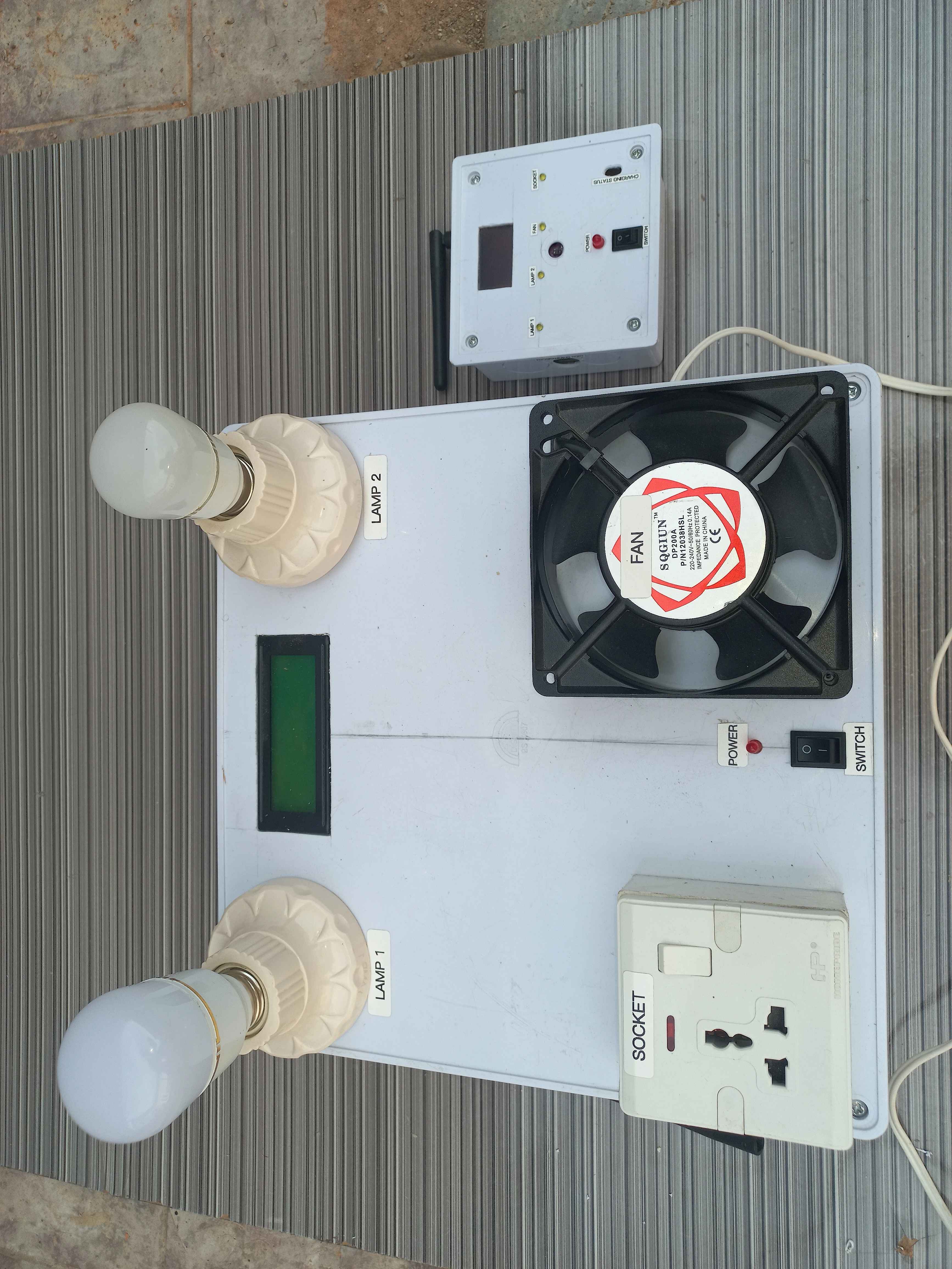
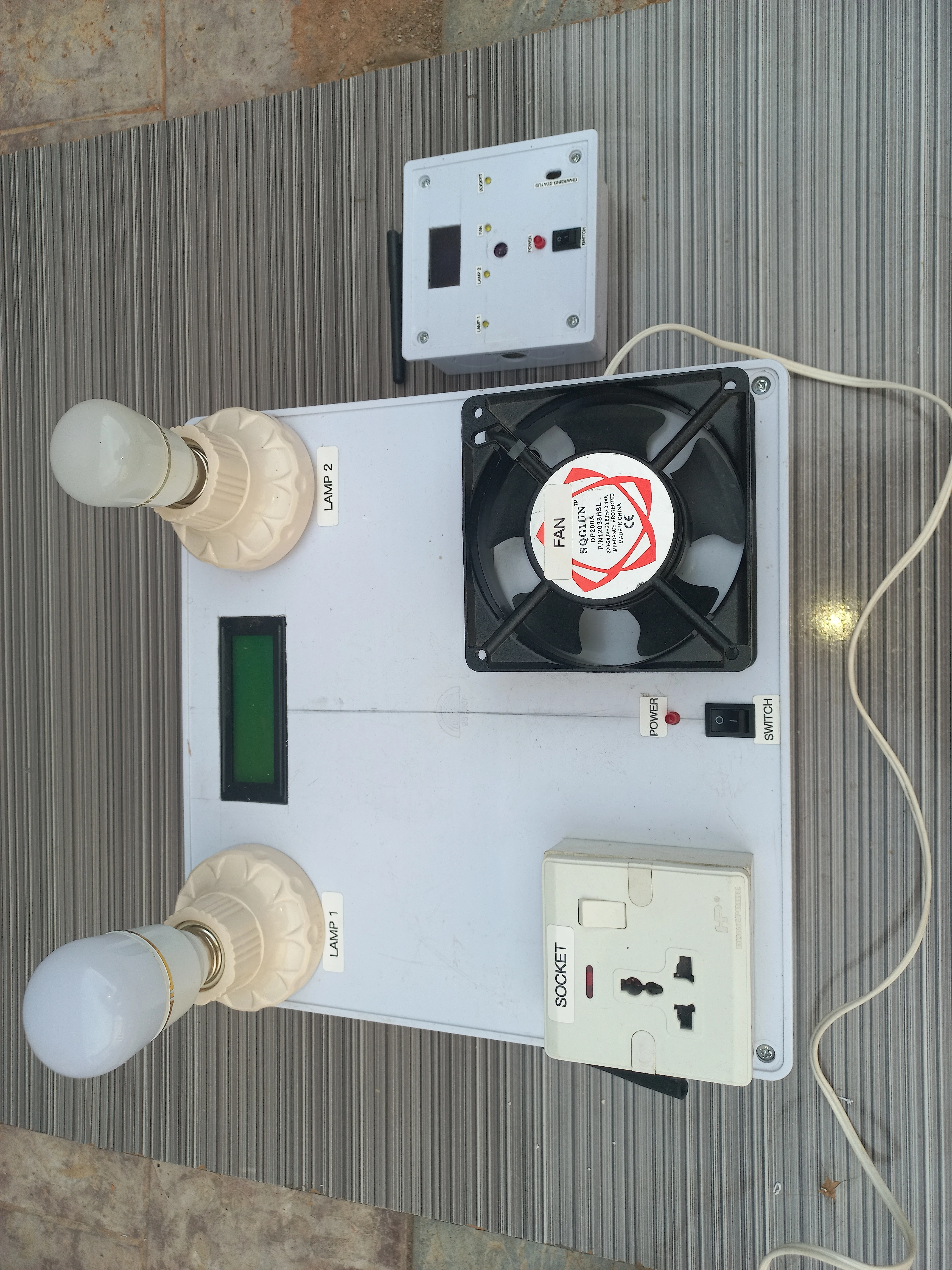
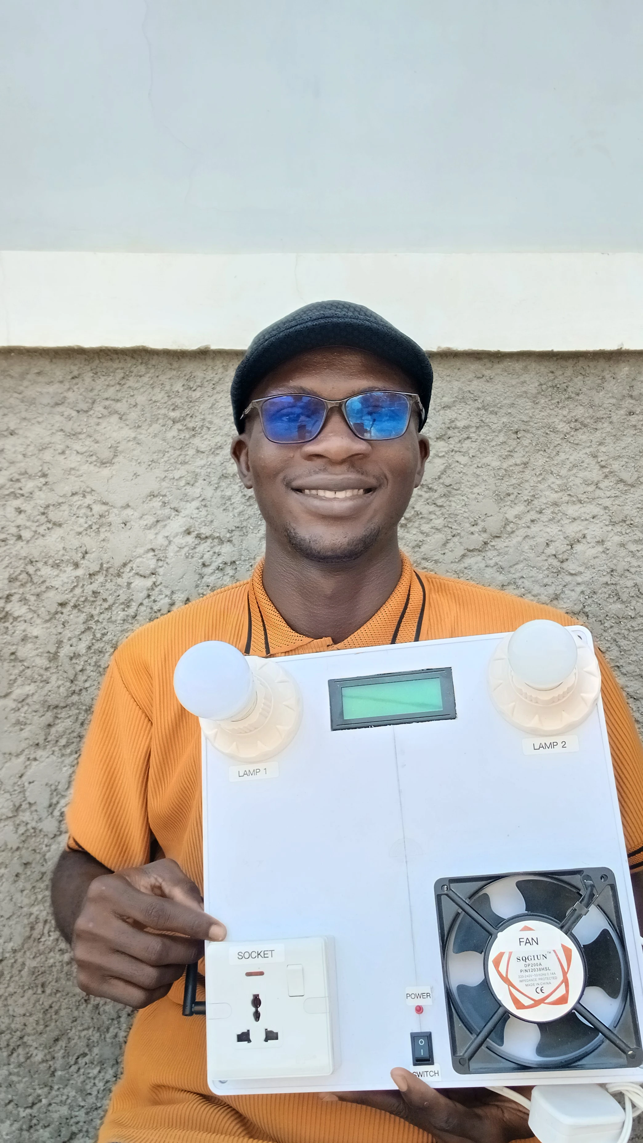
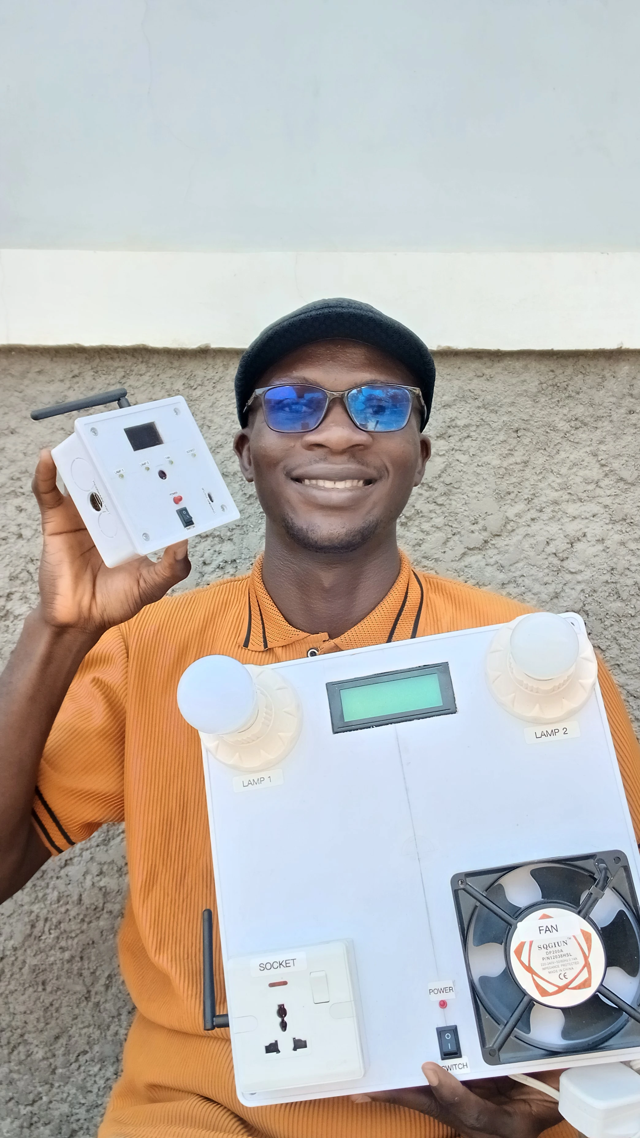
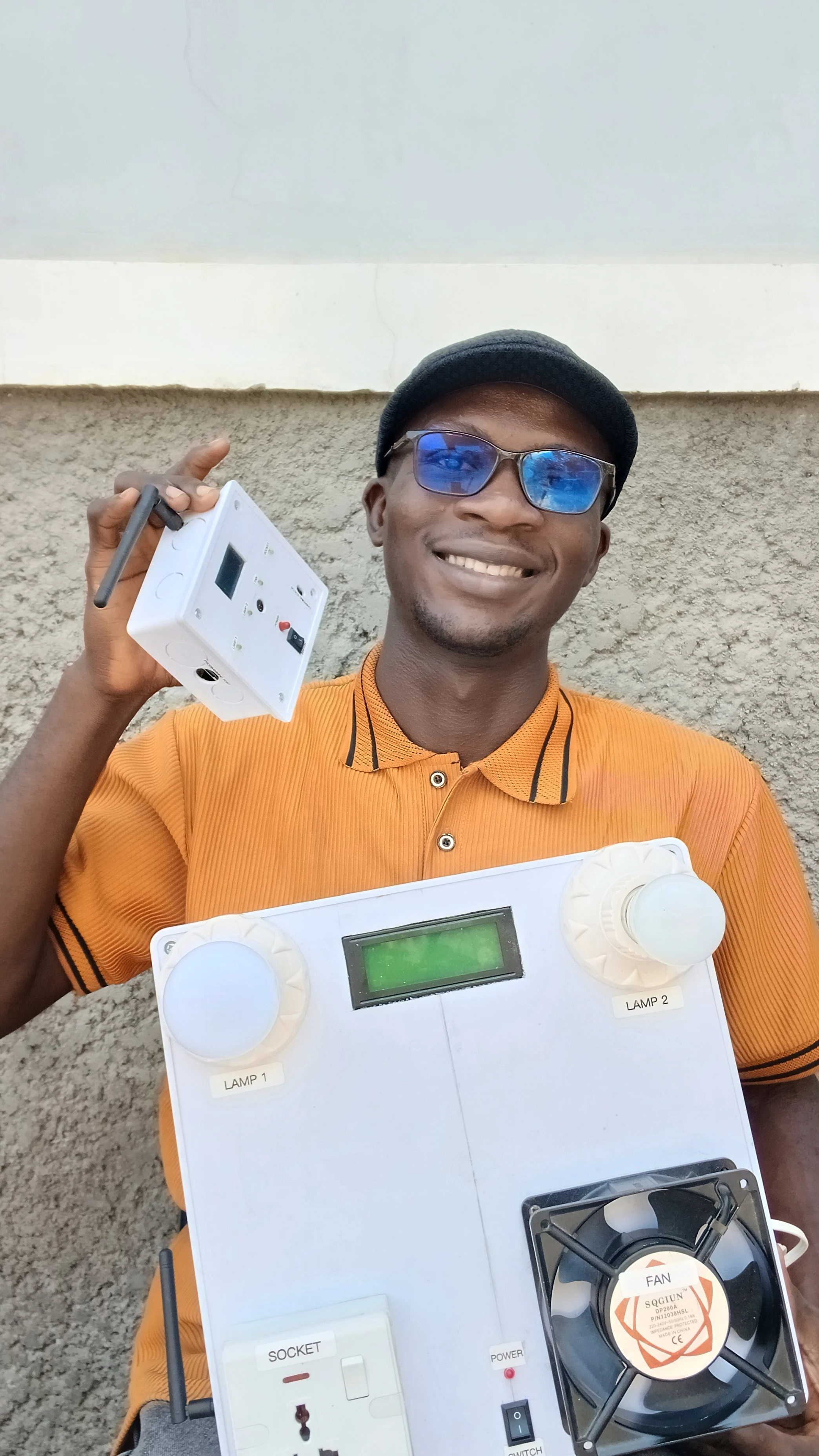
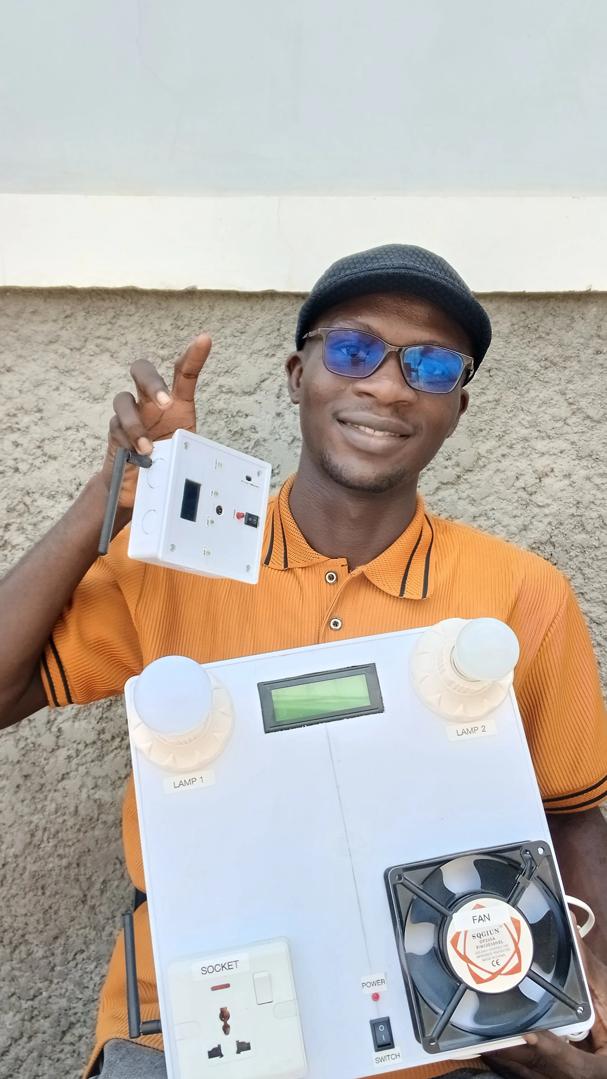
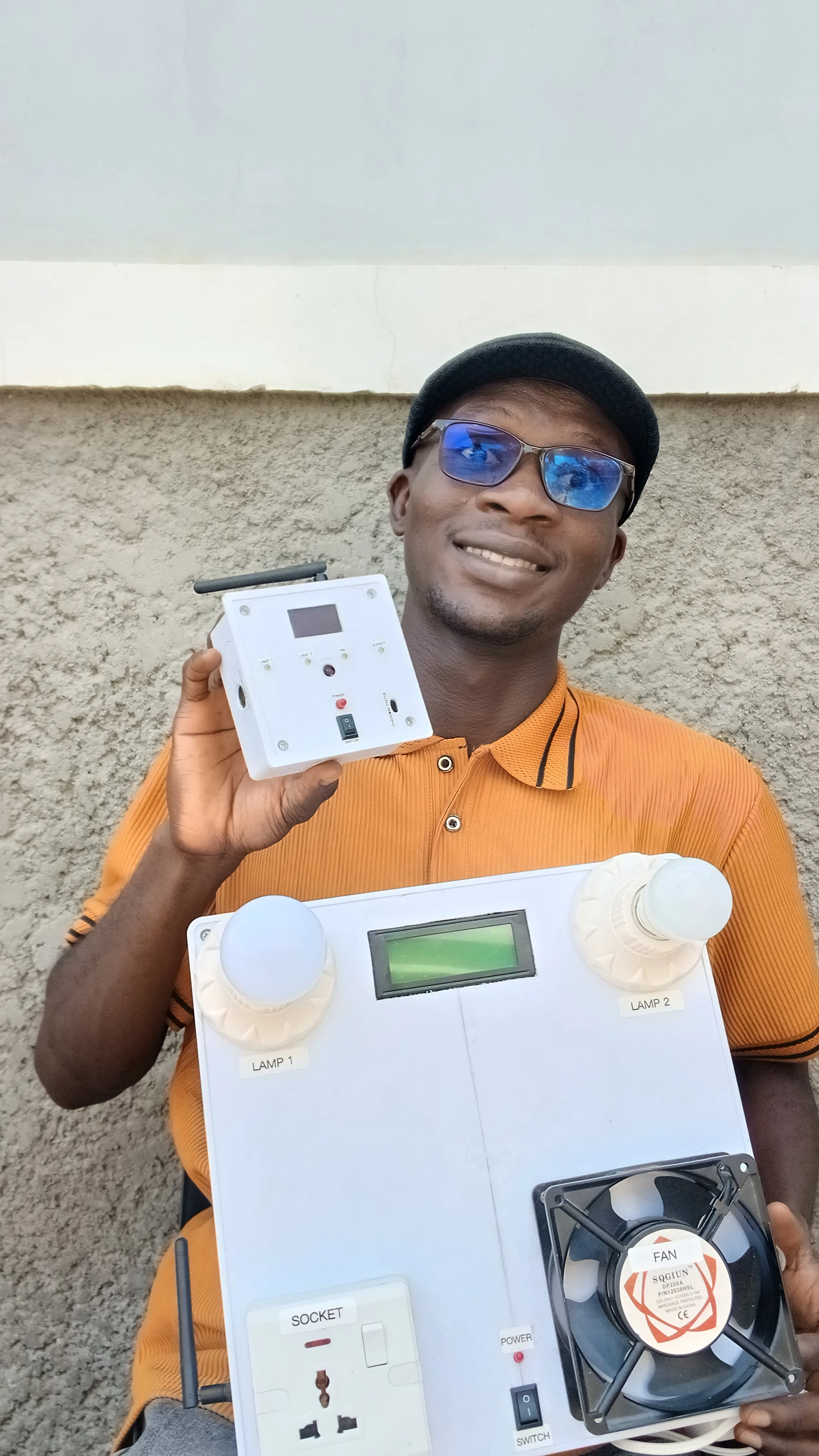
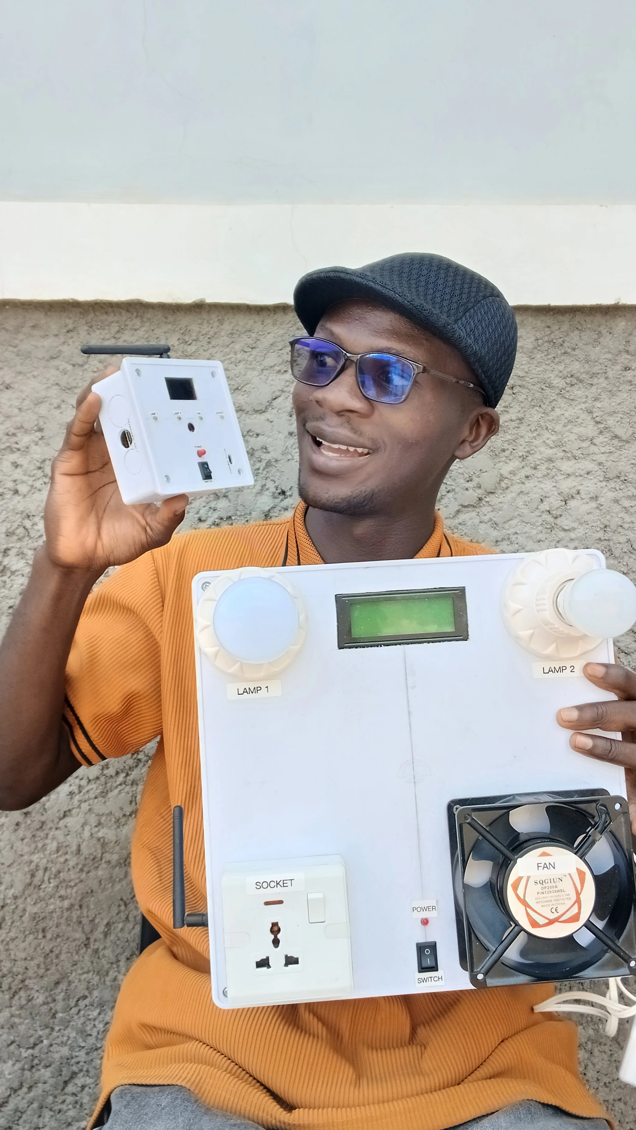
This project delivers a fully wireless, touchless smart home control system built around two Arduino Nano units connected via an NRF24L01 2.4GHz RF link. The transmitter unit houses an APDS9960 gesture sensor that reads hand swipes in four directions and maps them to individual appliances. Each detected gesture toggles the corresponding appliance state and transmits a command string wirelessly to the receiver unit. The receiver drives a 4-channel active-LOW relay board to physically switch the connected loads: Fan, Socket, Lamp 1, and Lamp 2. A 20x4 I2C LCD on the receiver displays a live "SMART CONTROL" dashboard. The transmitter is battery-powered with a rechargeable Li-Polymer cell and a TP4056 charging circuit, making it fully portable with no tethered power cable needed.
A key engineering challenge was RF interference from the relay coil switching disturbing the NRF24L01 link. This was solved by setting aggressive retry logic (15 retries, 15 delay steps) on the transmitter radio, which ensures reliable command delivery even during relay transients. The transmitter also shows a splash screen on boot before entering gesture detection mode.
The system is composed of two independent, battery or mains-powered units that communicate over a peer-to-peer 2.4GHz RF link:
  [Hand Gesture]
       |
  APDS9960 Sensor (Transmitter Nano, I2C 0x39)
       |
  Map gesture -> command string ("U ON", "D OFF", etc.)
       |
  NRF24L01 TX (CE=D9, CSN=D10, pipe "ADDRESS01")
       |  ~~ 2.4GHz RF ~~
  NRF24L01 RX (CE=D9, CSN=D10, pipe "ADDRESS01")
       |
  Arduino Nano Receiver
       |
  Parse command -> toggle relay state
       |
  applyOutputs() -> Relay A0/A1/A2/A3
       |
  [Appliance ON/OFF]  +  LCD update  +  Beep
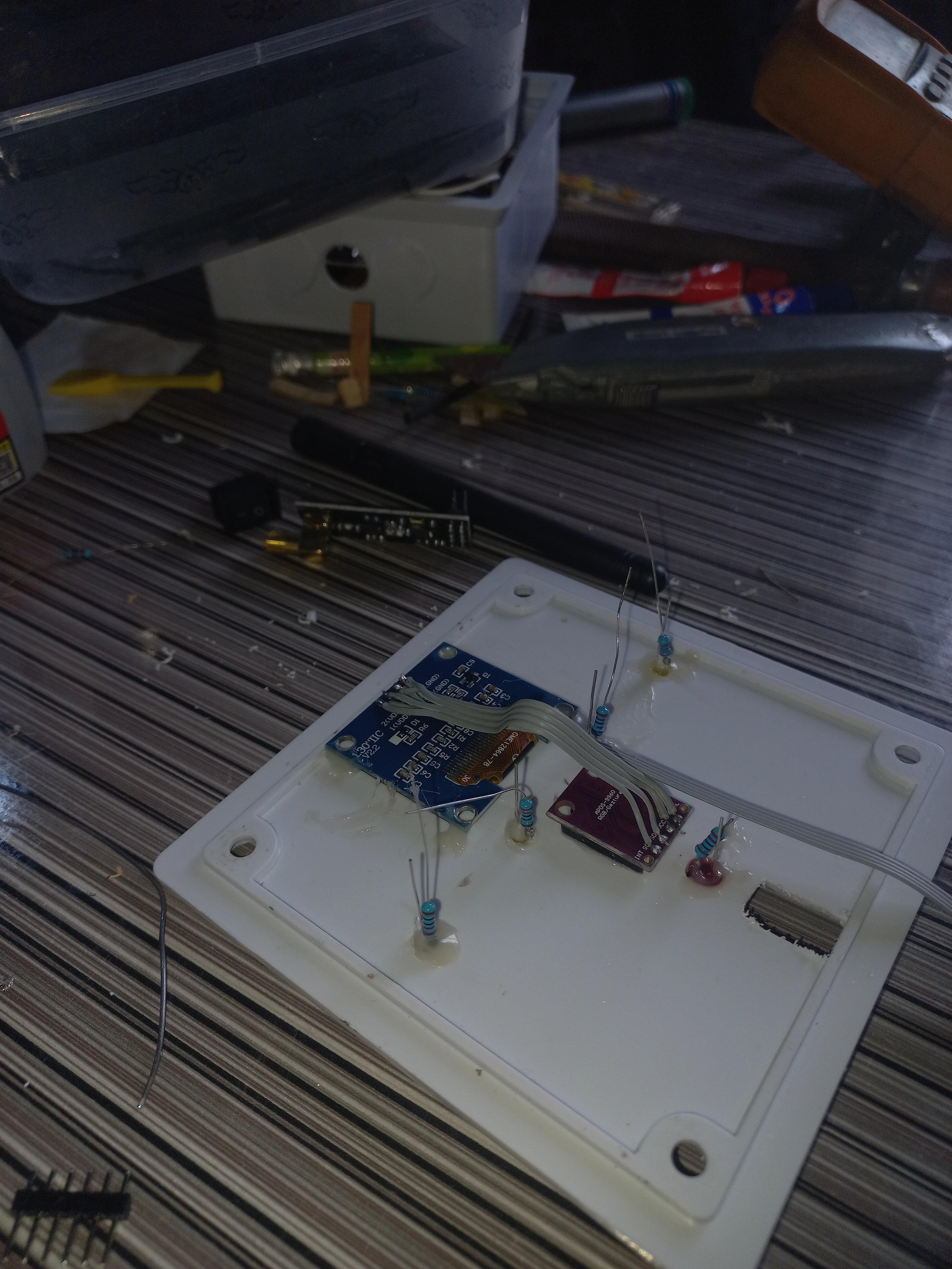
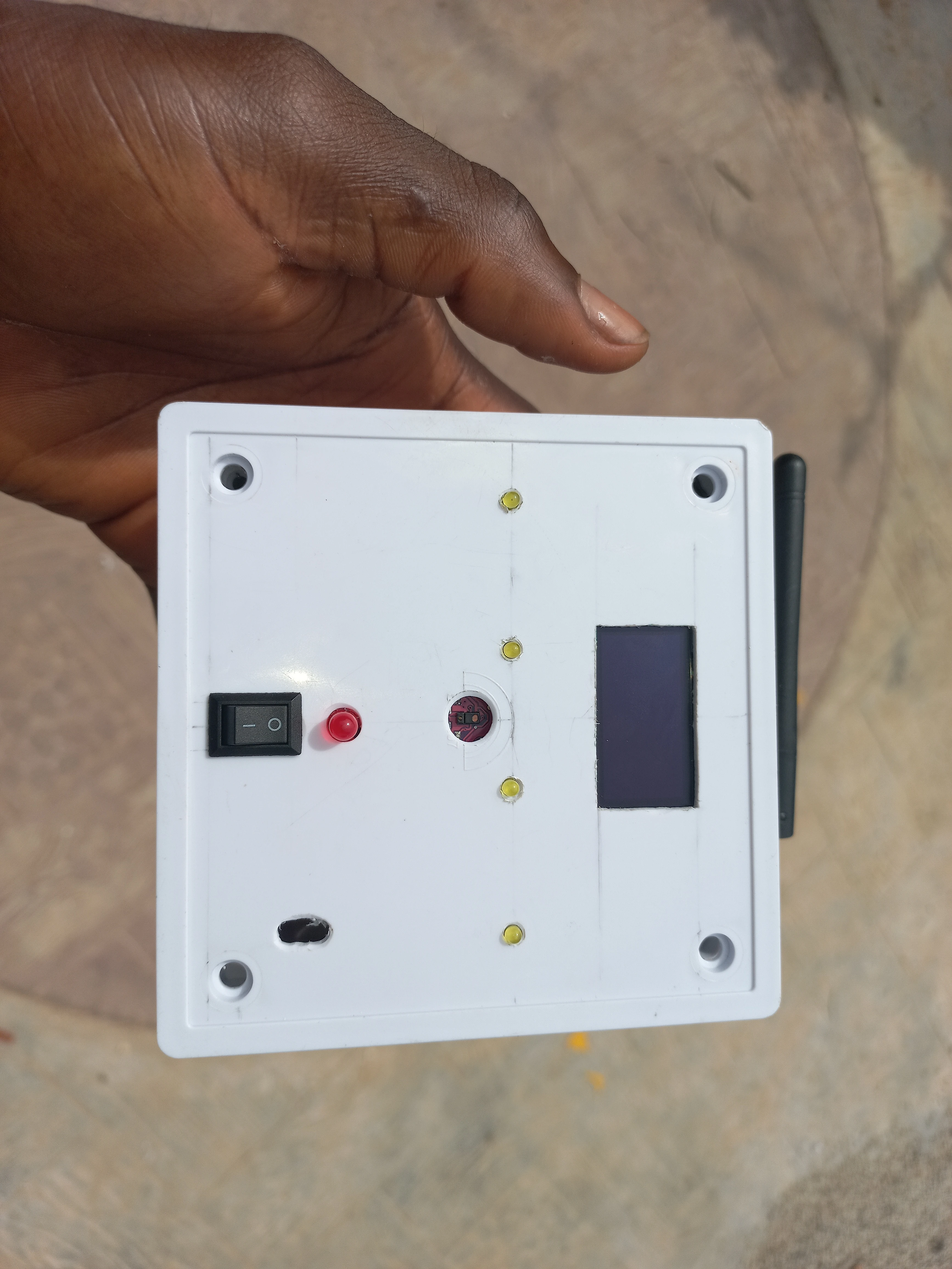
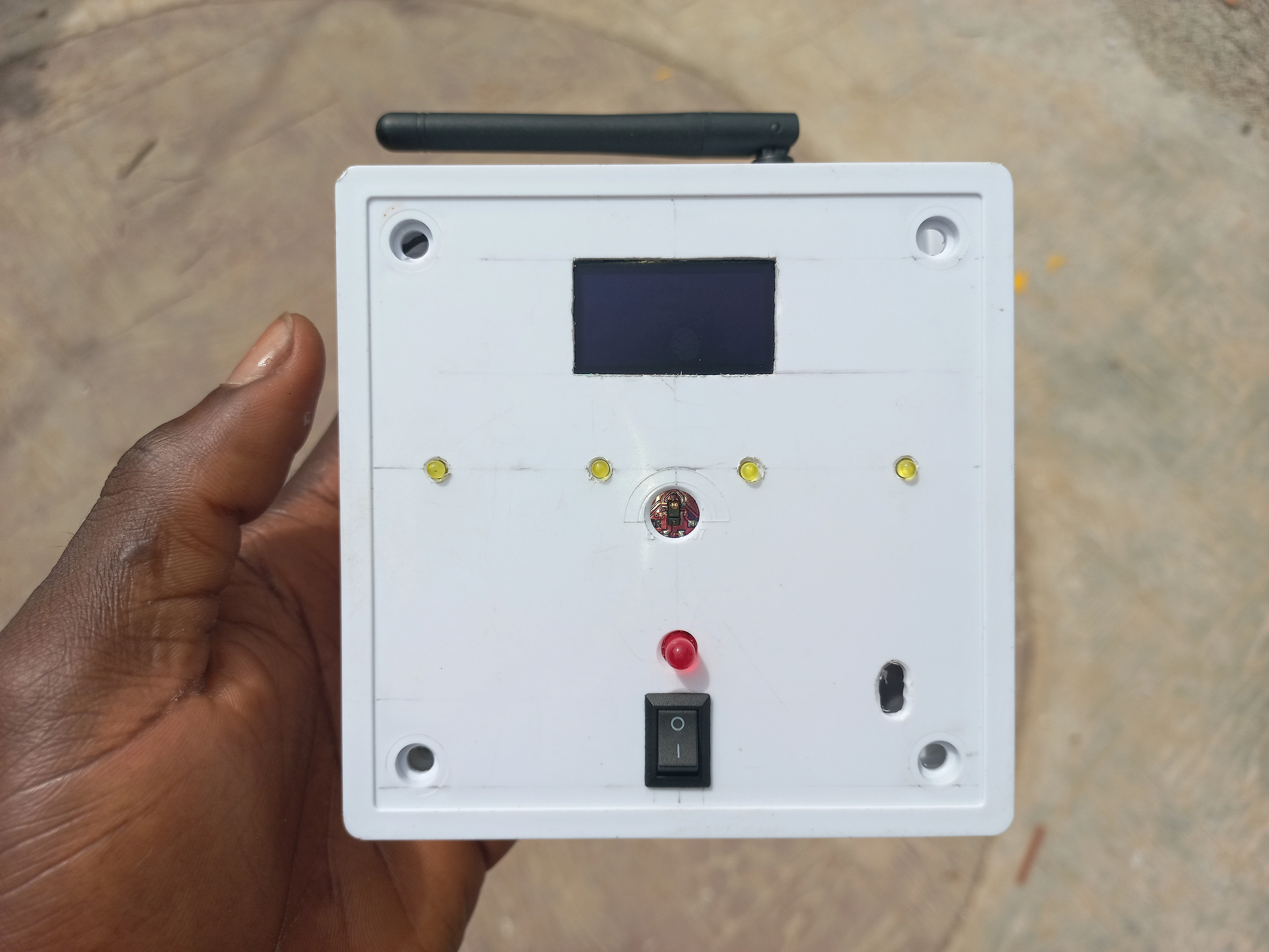
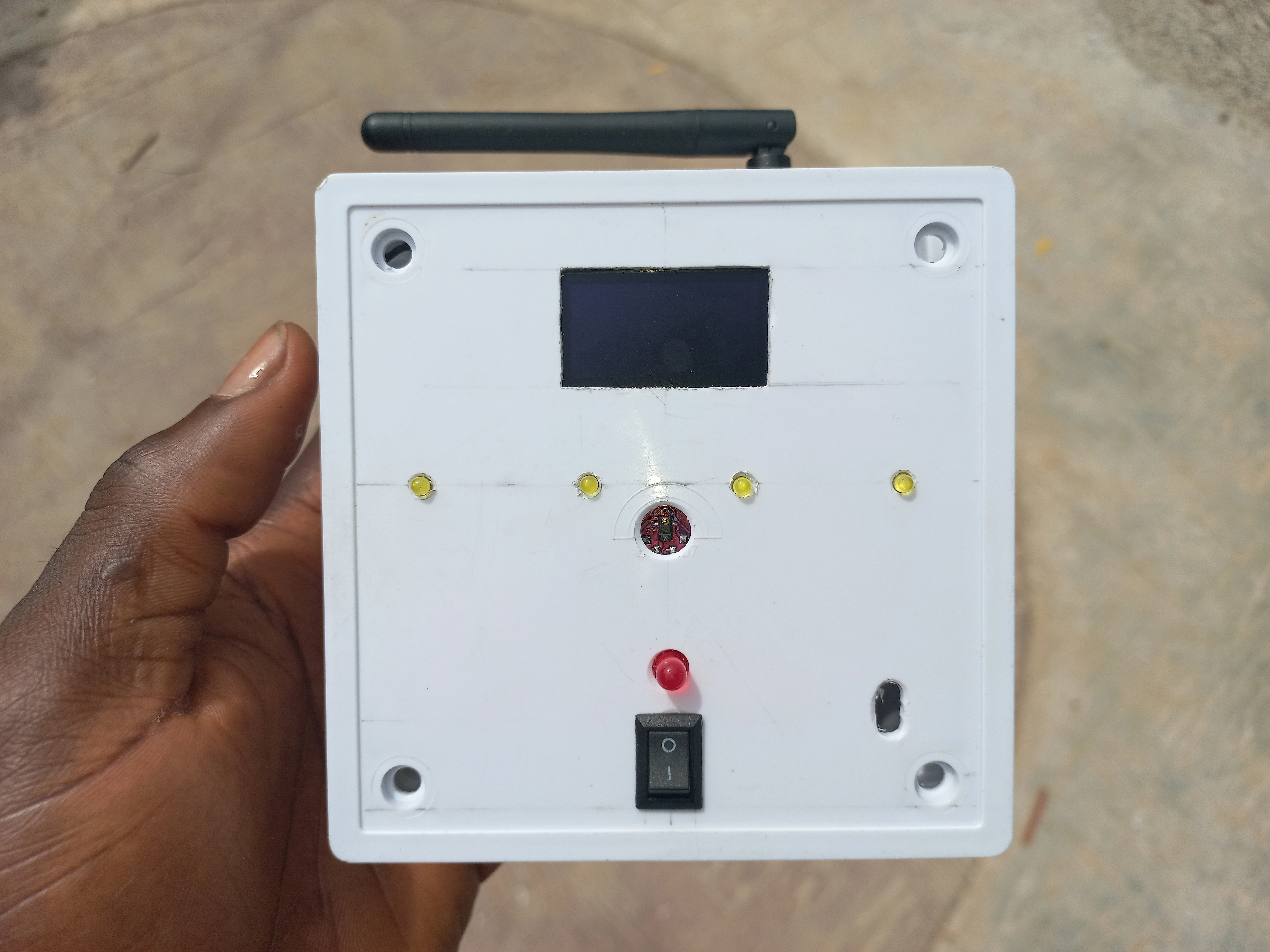
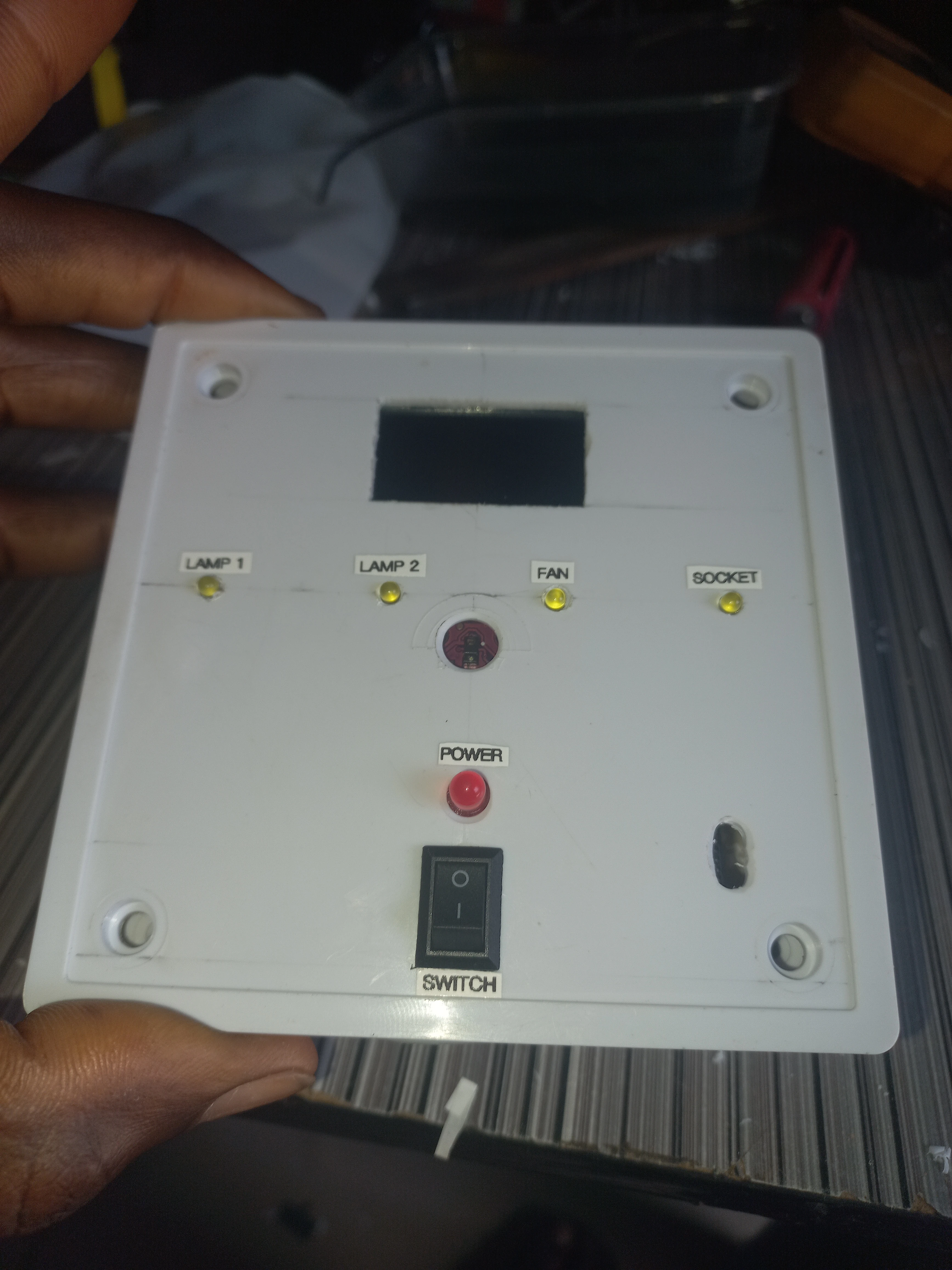
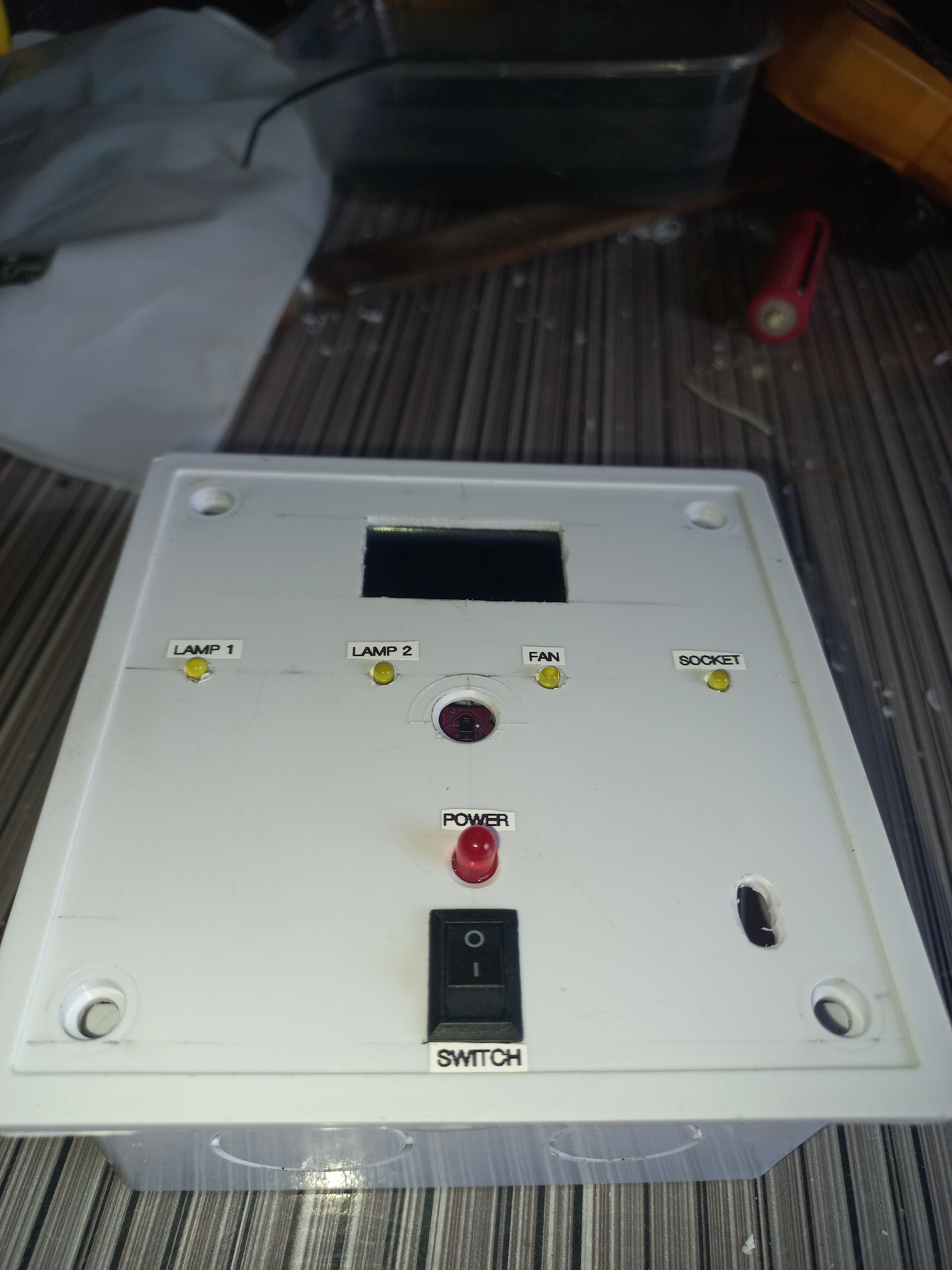
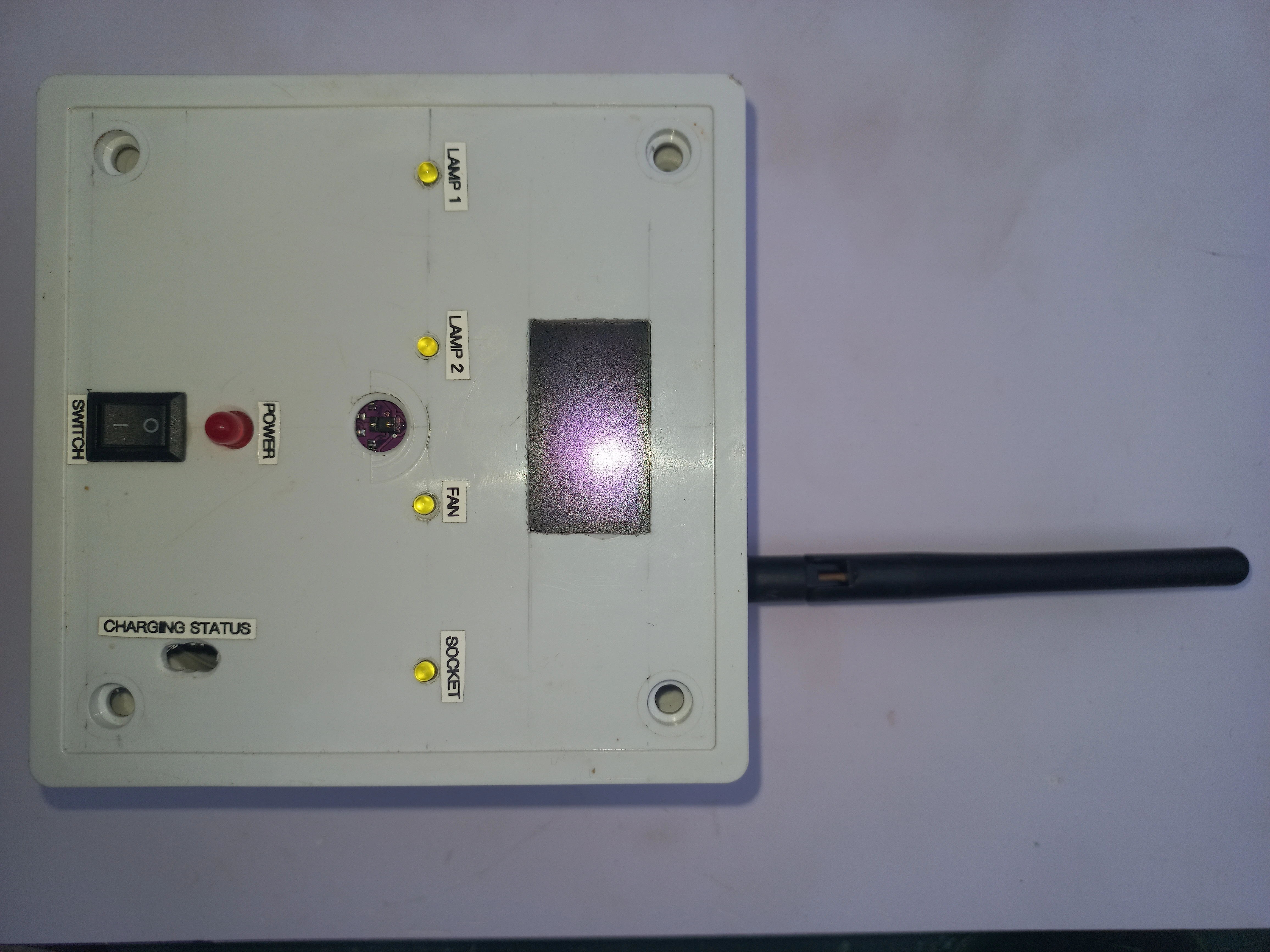
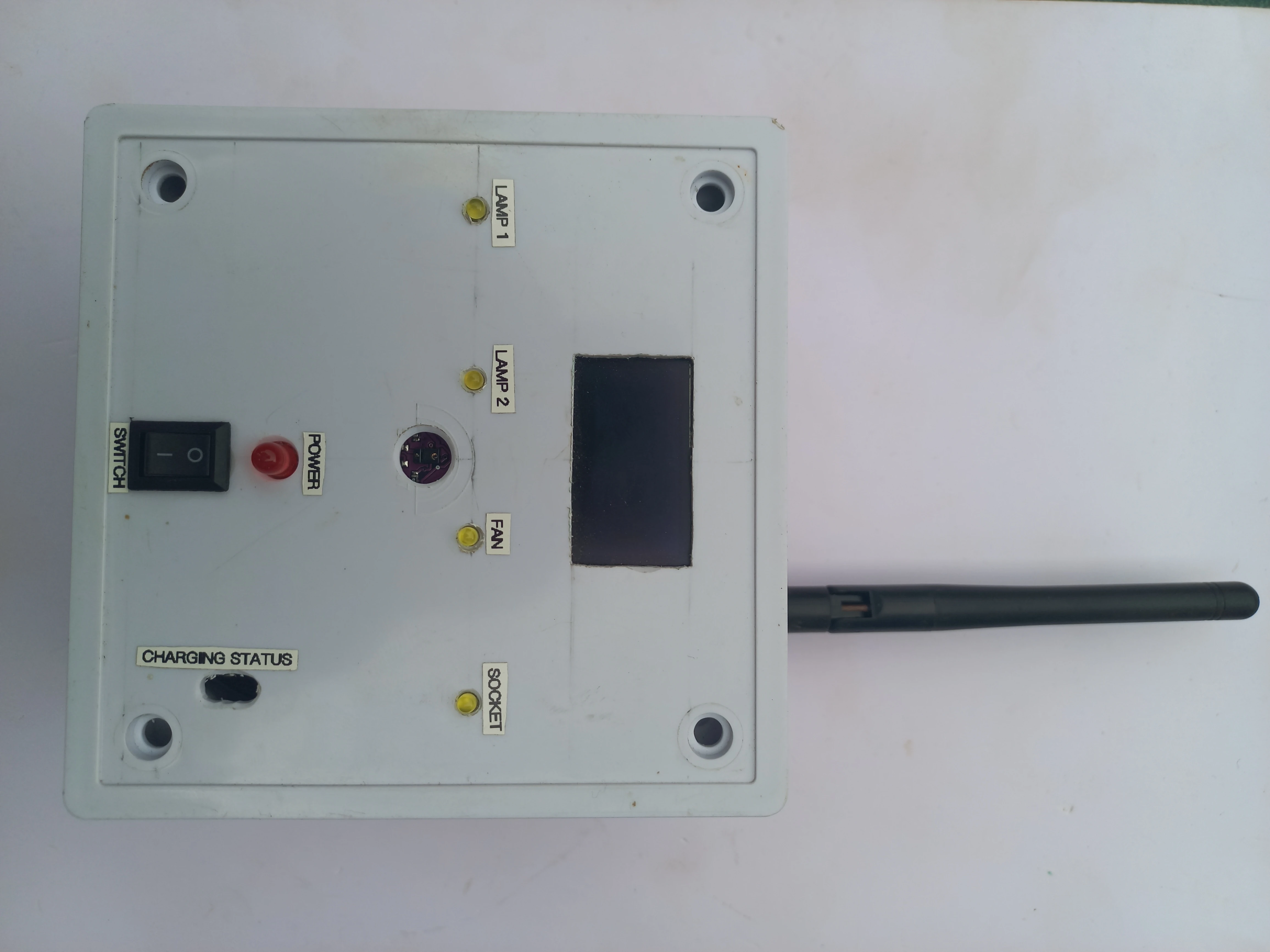
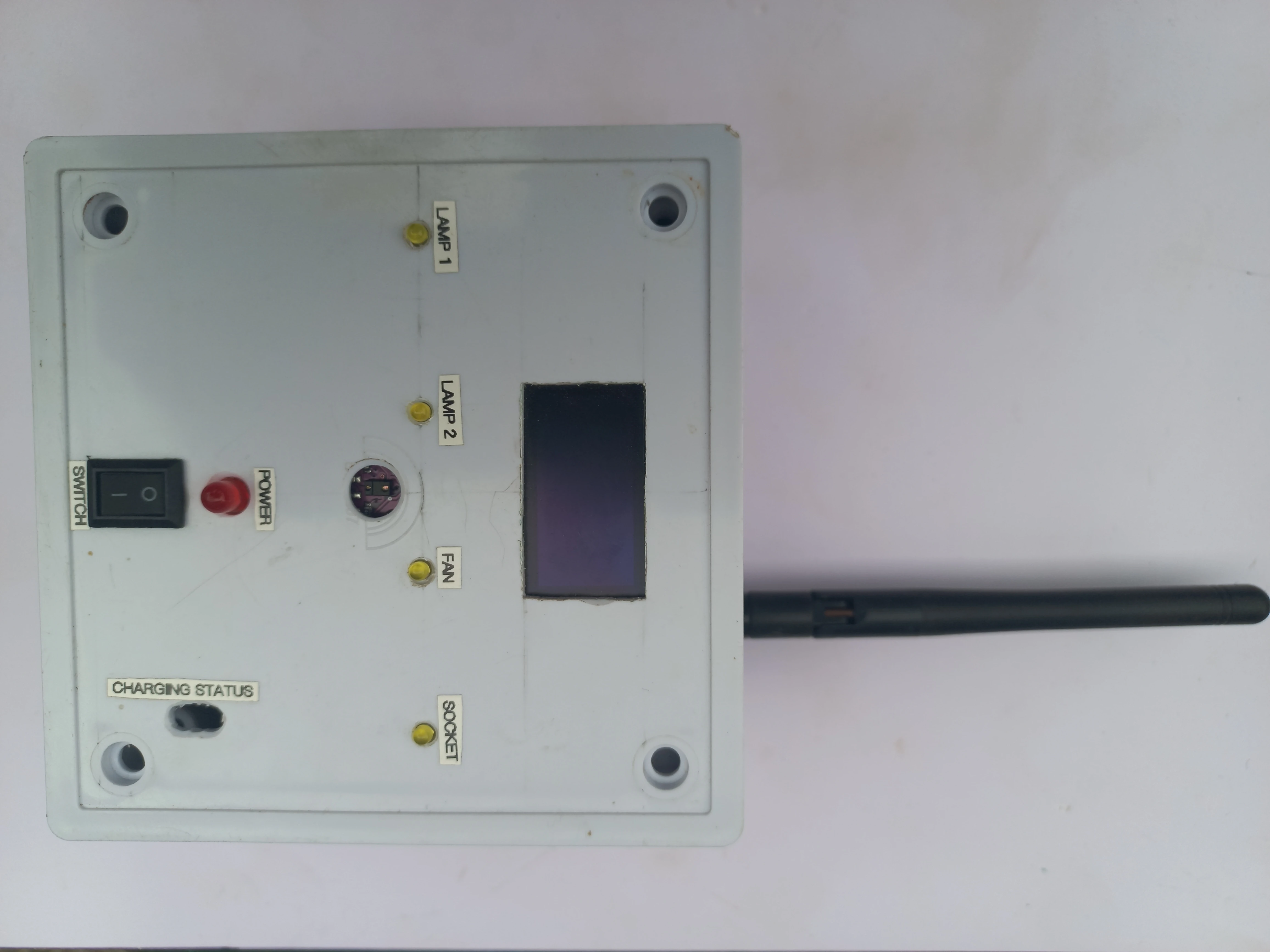
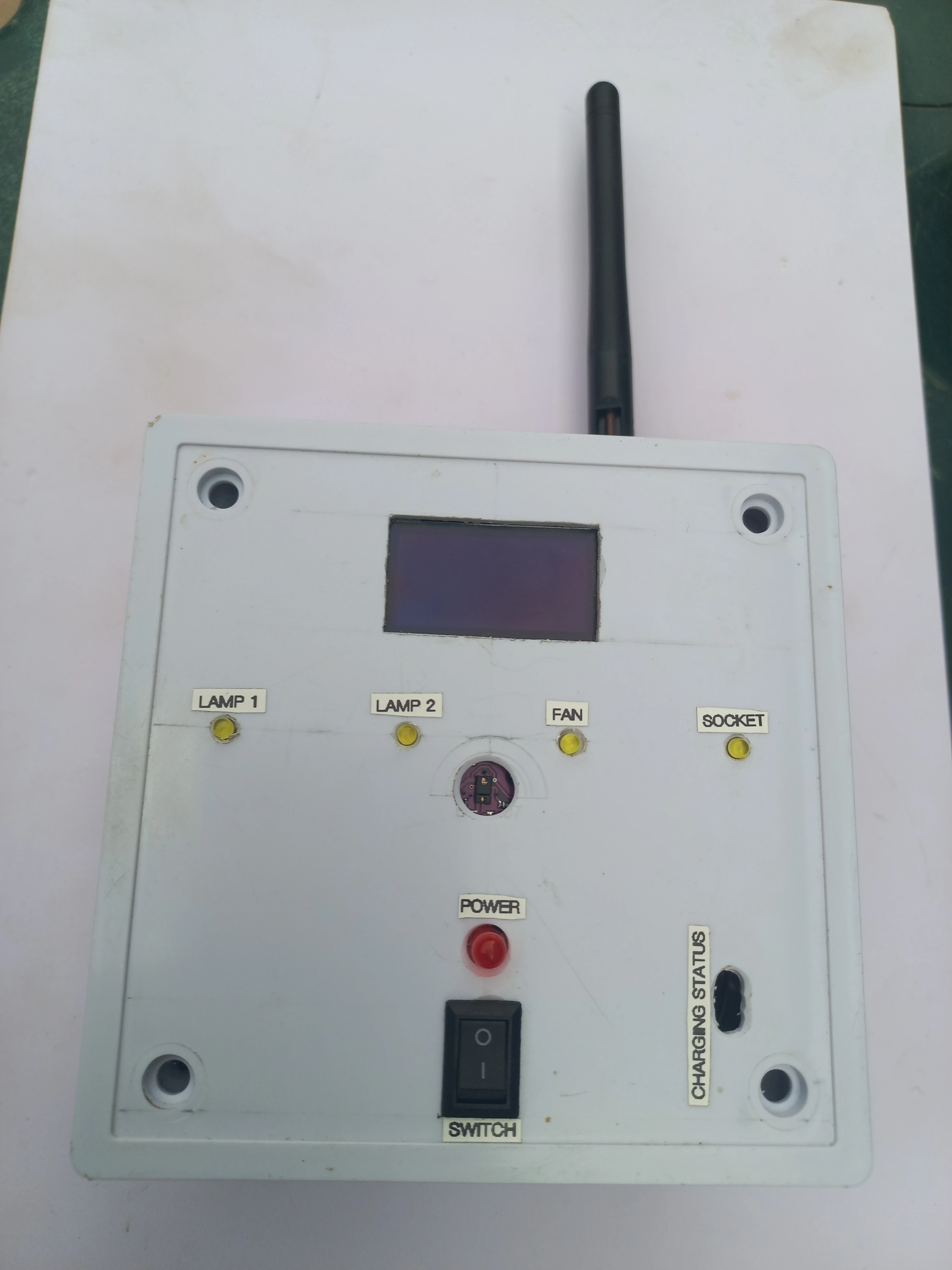
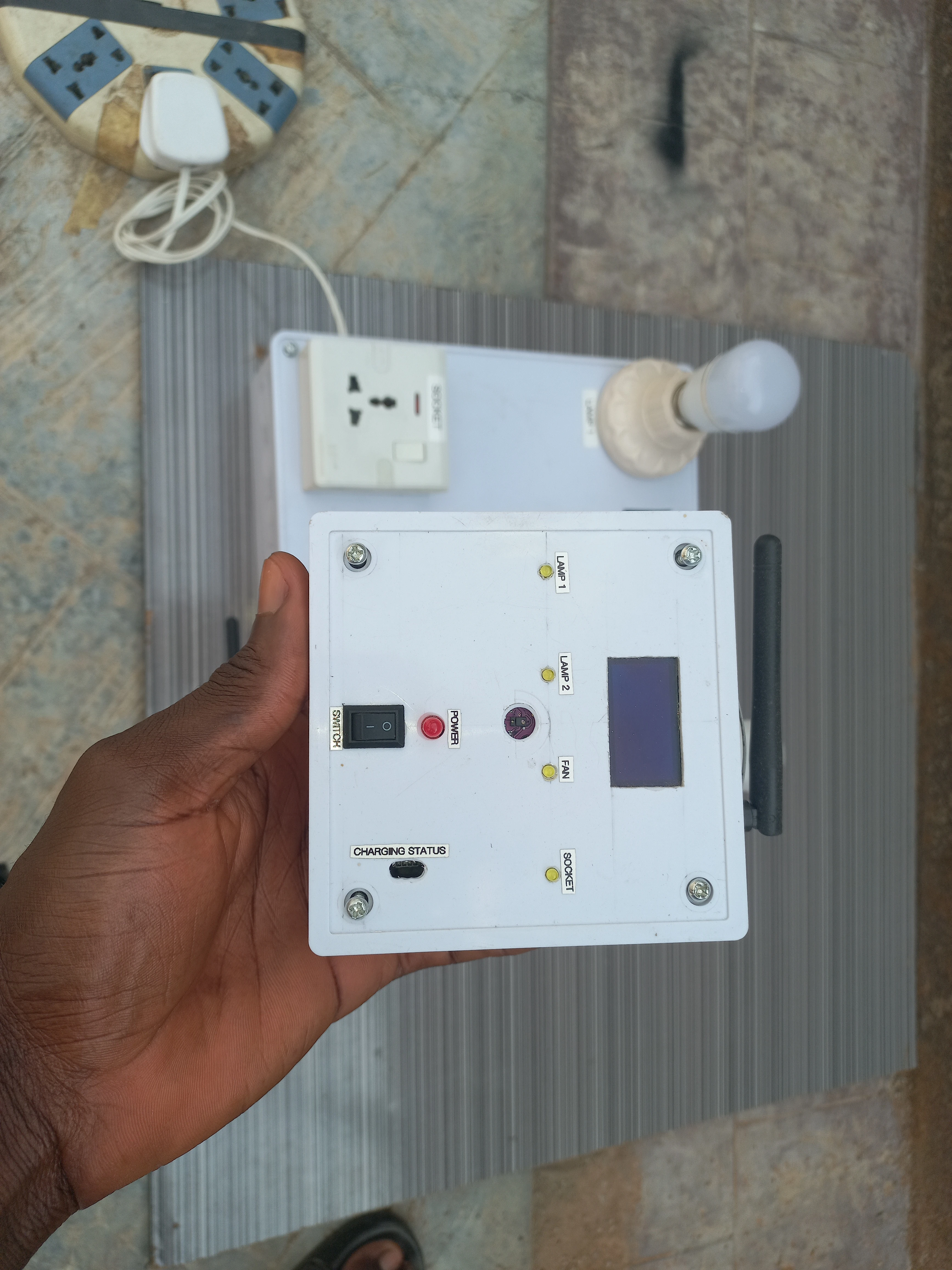
The transmitter also drives an SH1106 OLED that shows the detected gesture direction, device name, and ON/OFF state in real time. Four yellow LEDs on the transmitter face mirror the current state of each appliance so the user sees feedback without looking at the receiver panel.
| Component | Specification | Unit | Role |
|---|---|---|---|
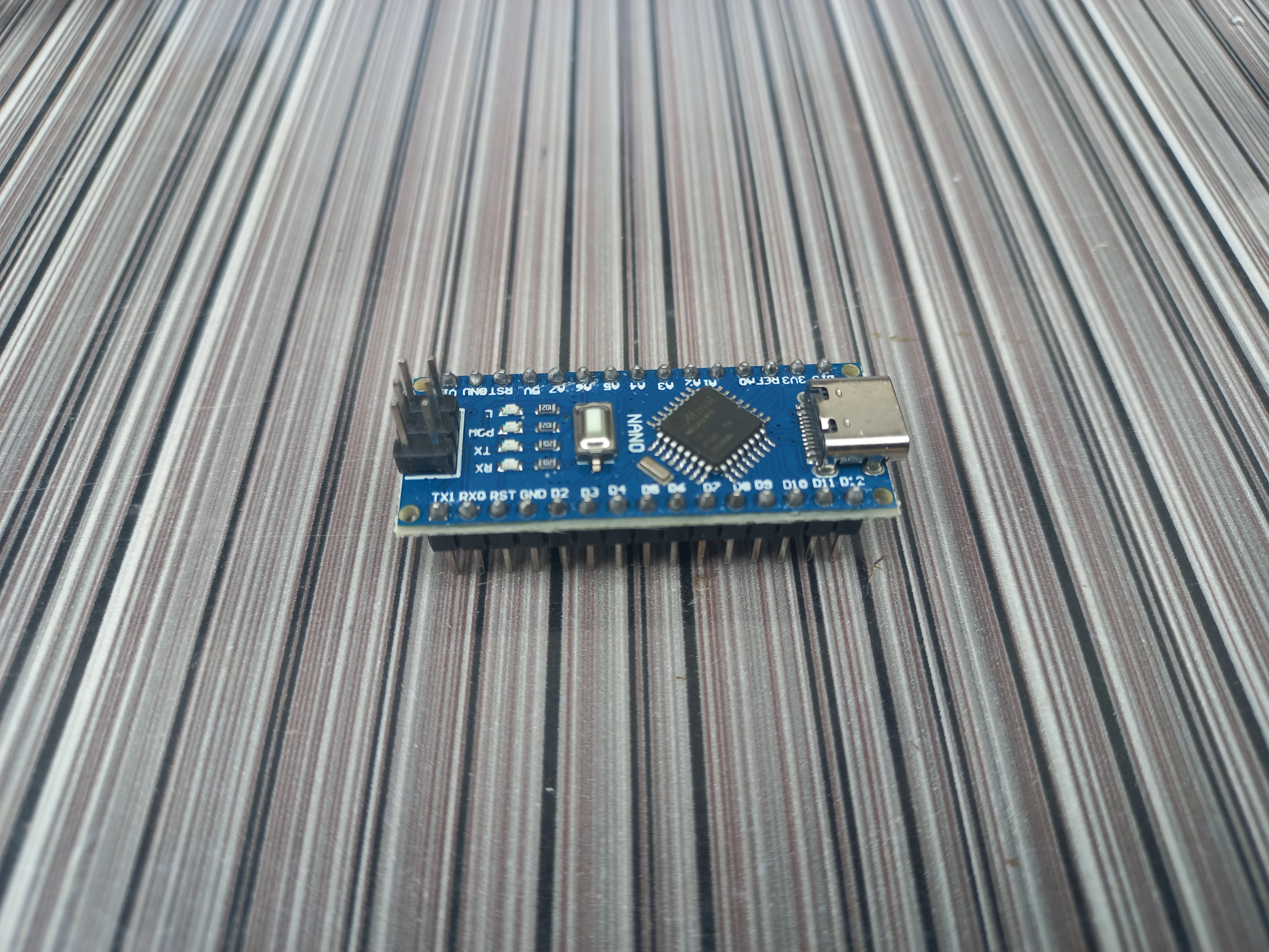
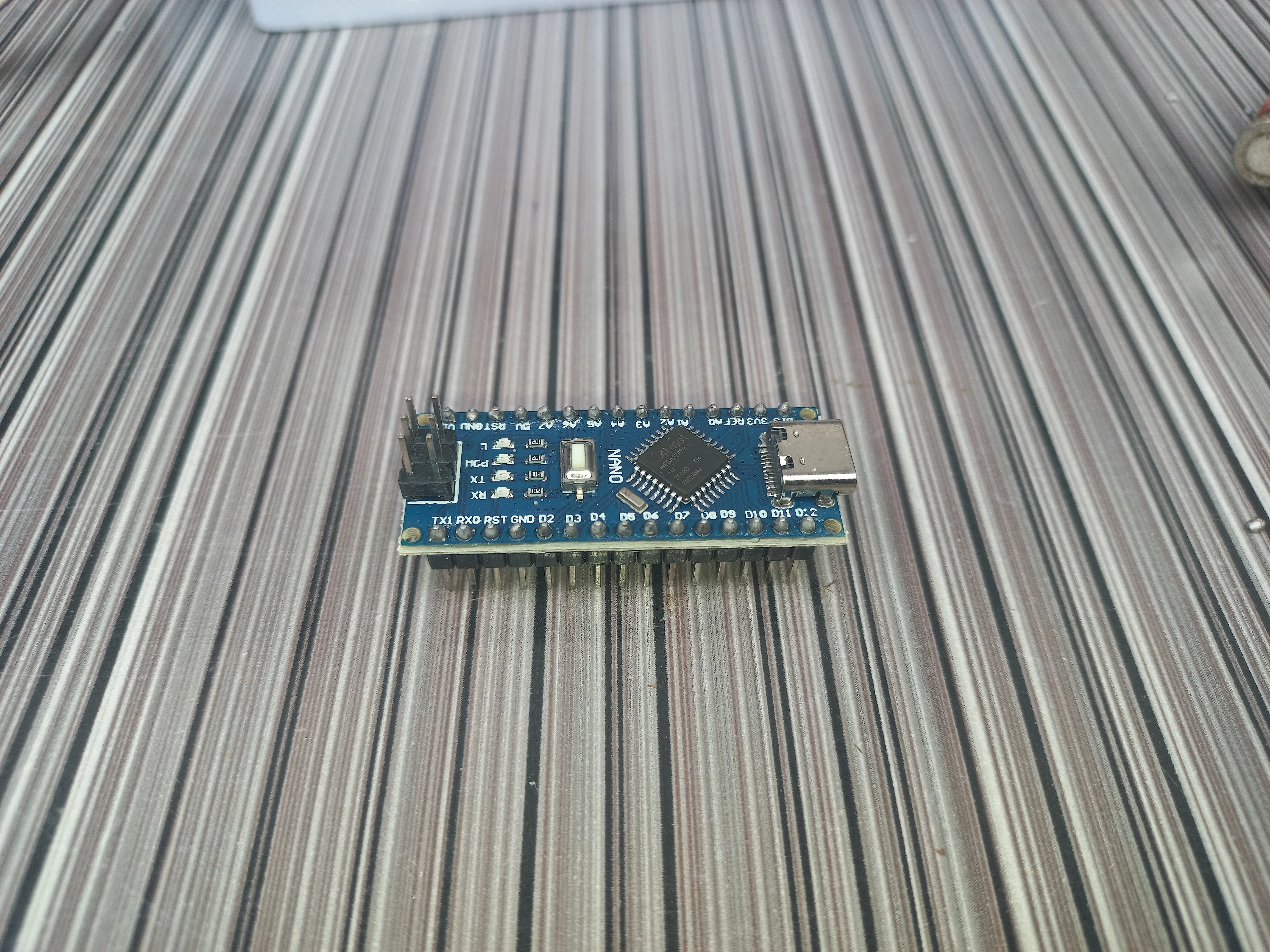
| Arduino Nano | ATmega328P, USB-C, 5V logic | 2 | Transmitter MCU + Receiver MCU |
| APDS9960 | Proximity, gesture, ambient light (I2C 0x39) | 1 | Gesture input on transmitter |
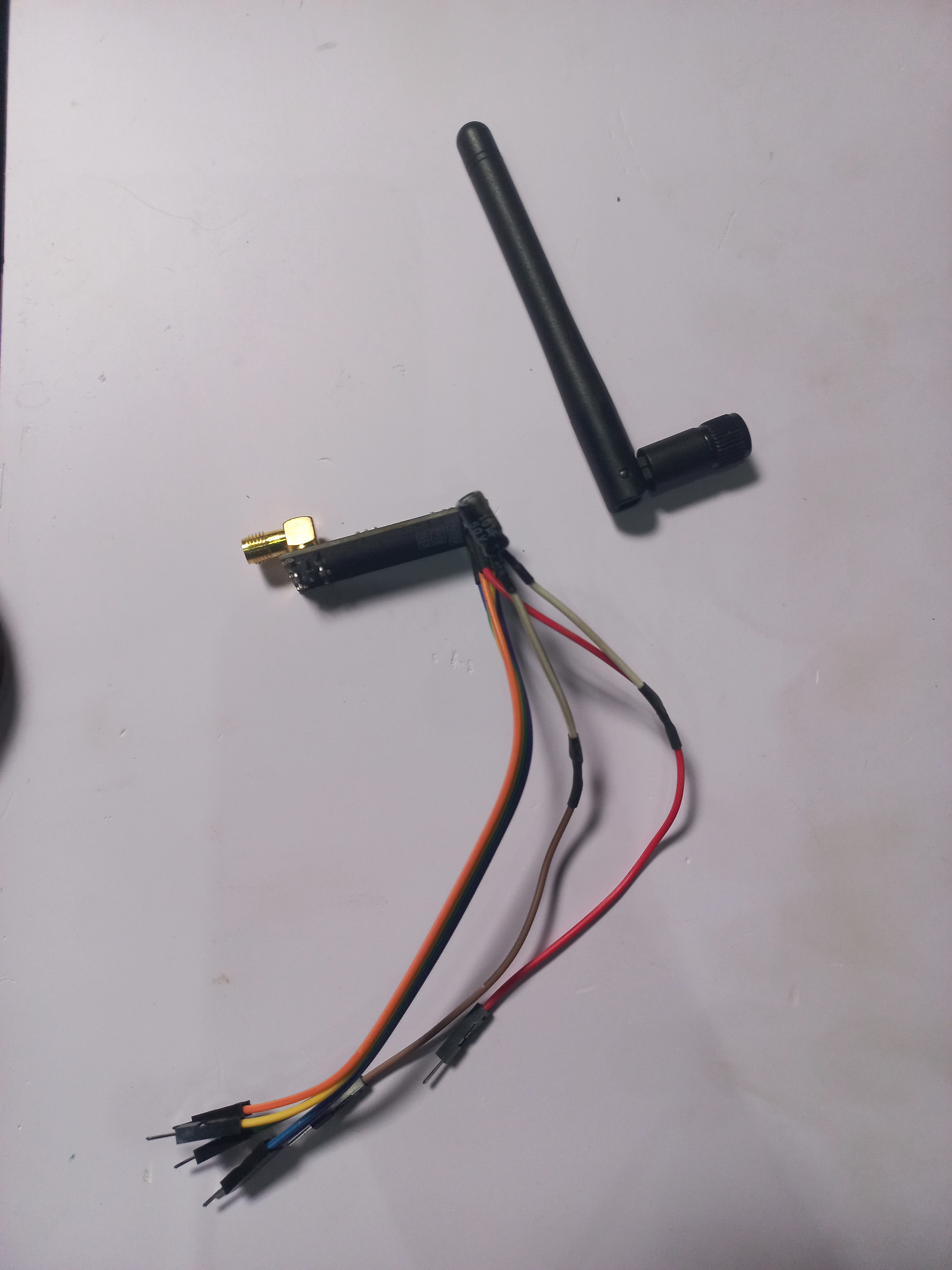
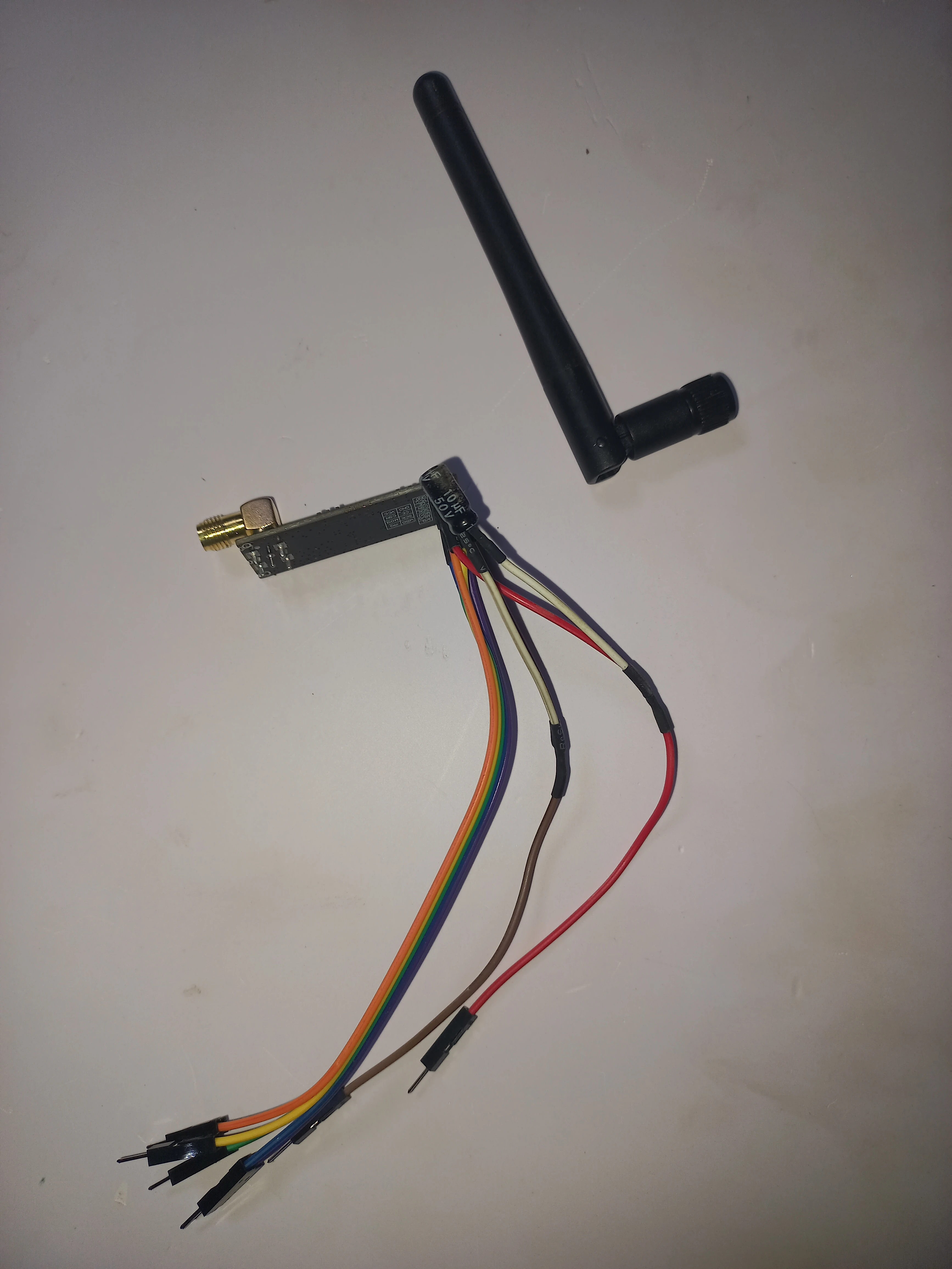
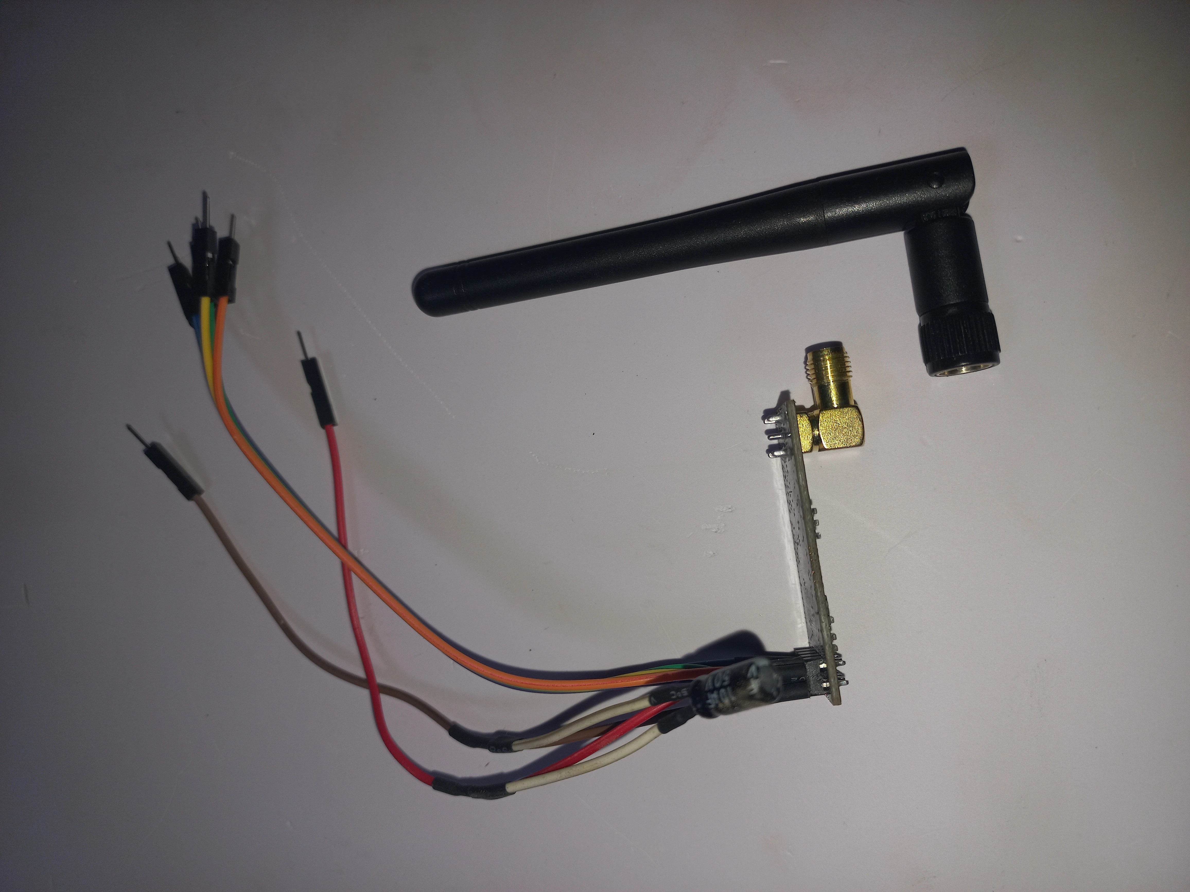
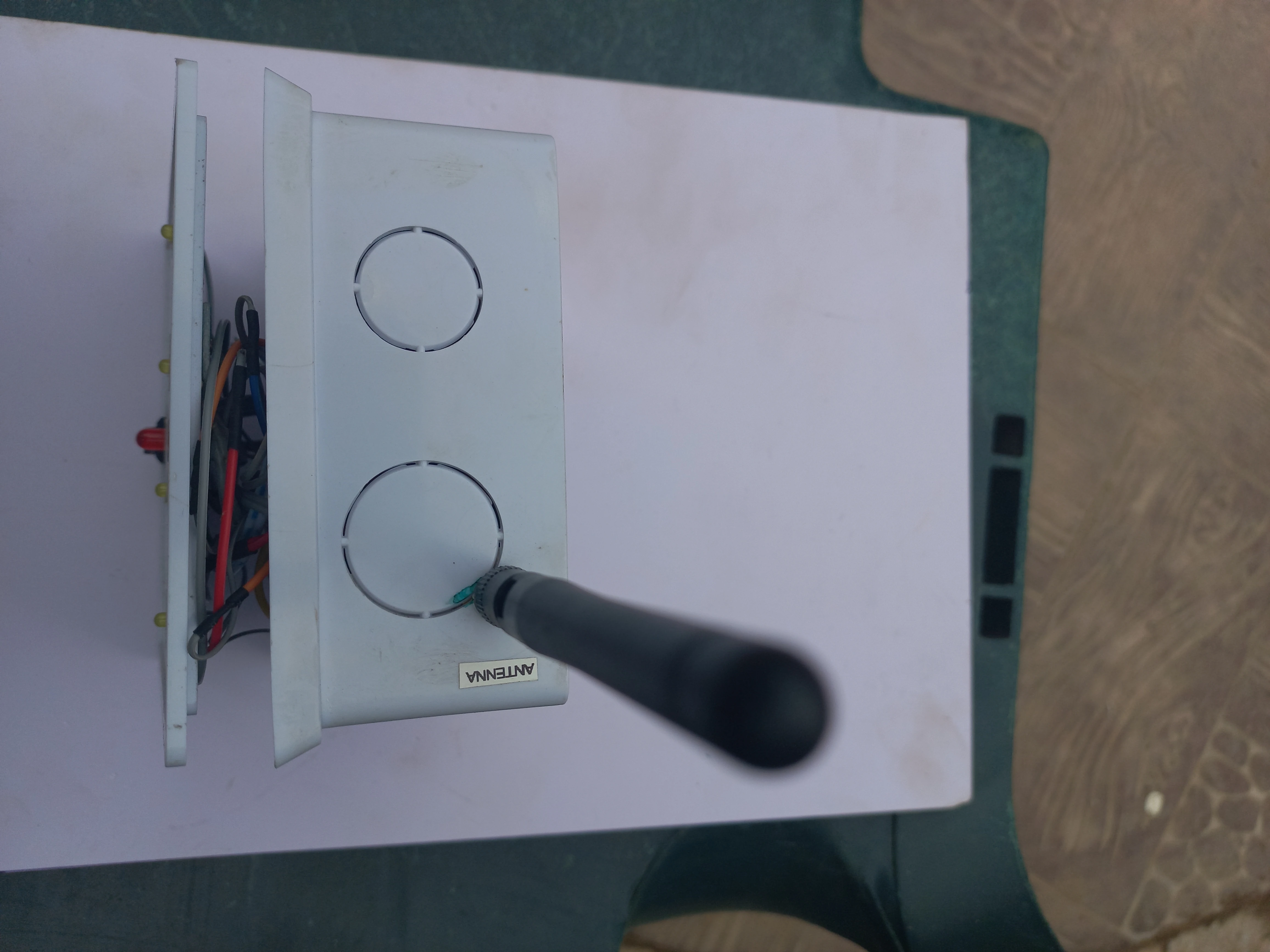
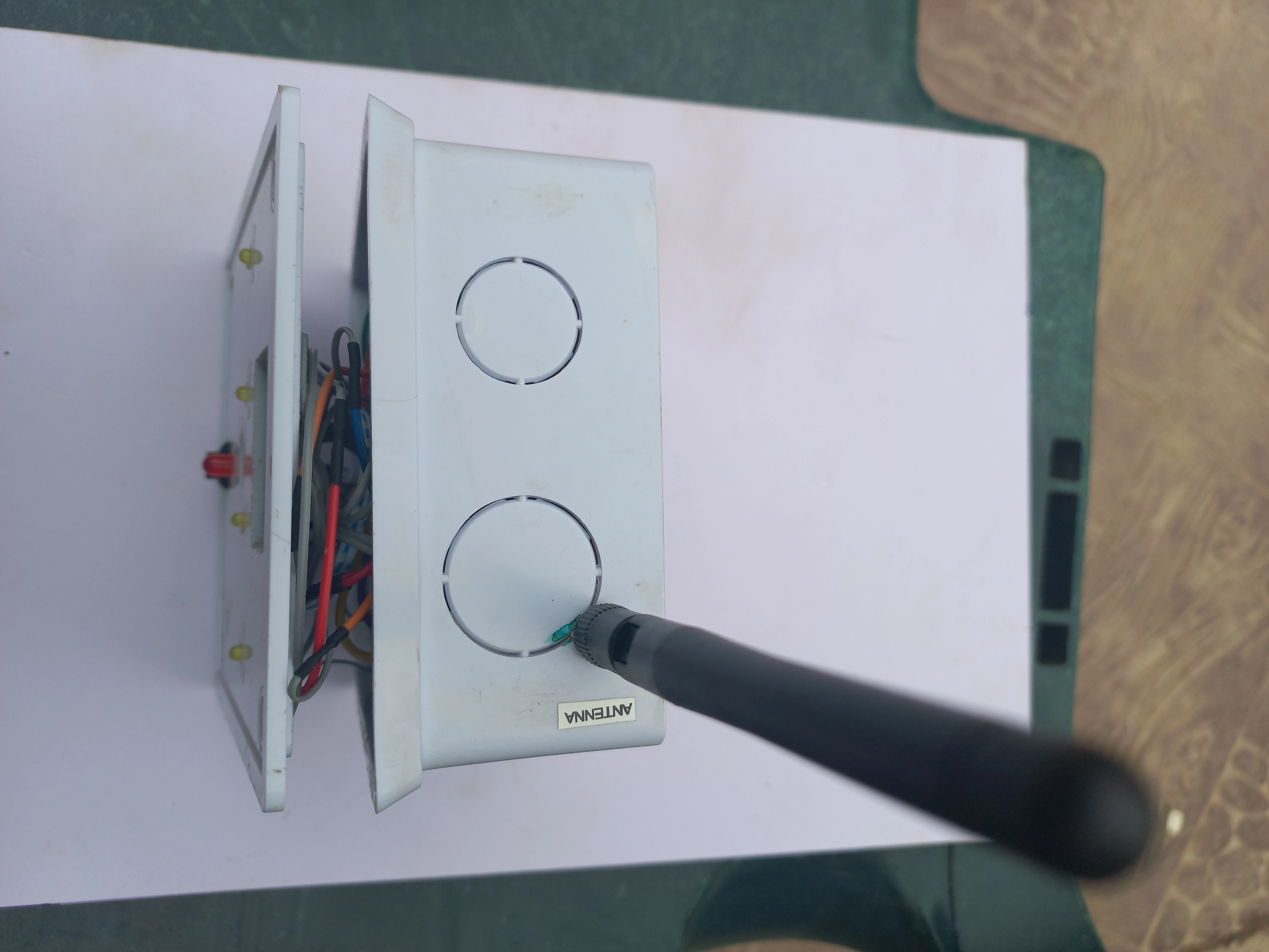
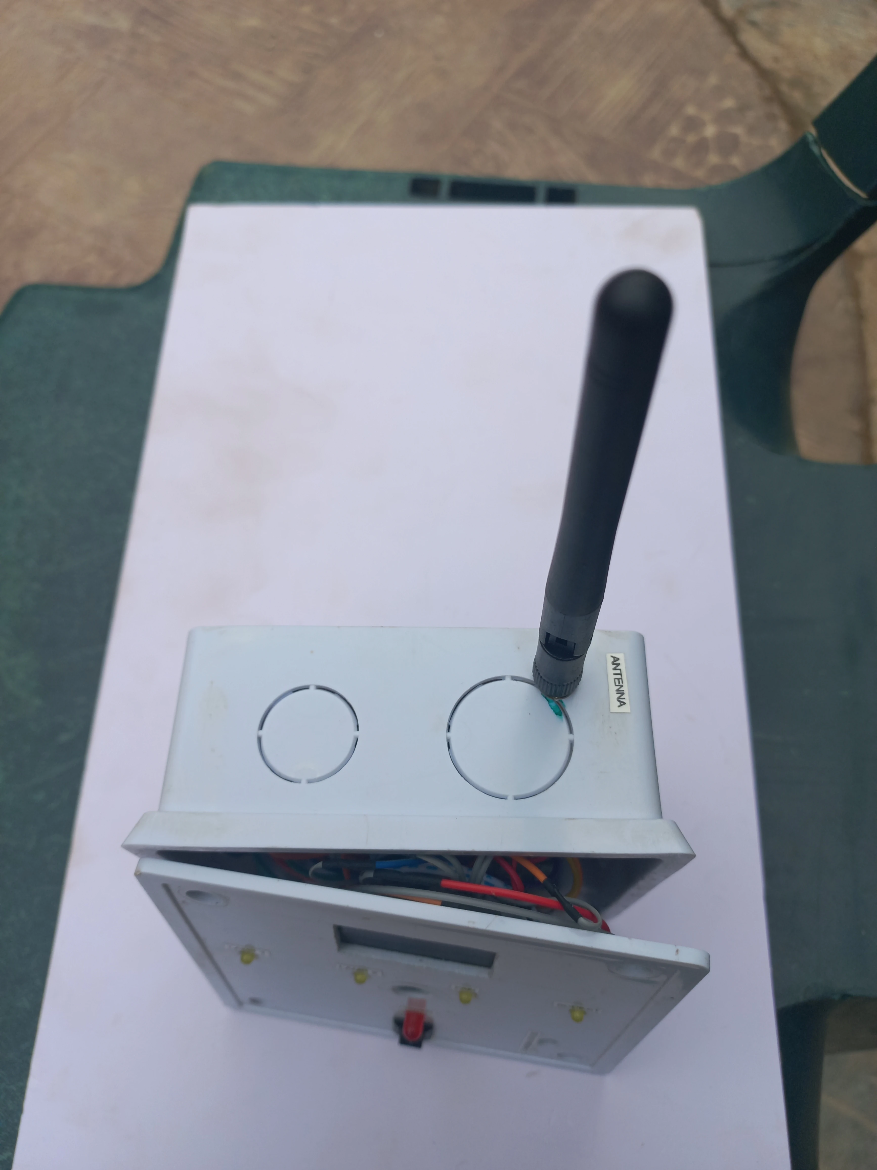
| NRF24L01 (SMA) | 2.4GHz, SPI, SMA external antenna, CE=D9 CSN=D10 | 2 | Wireless RF link (TX + RX) |
| SH1106 OLED | 1.3", 128x64, I2C (U8g2 driver) | 1 | Status display on transmitter |
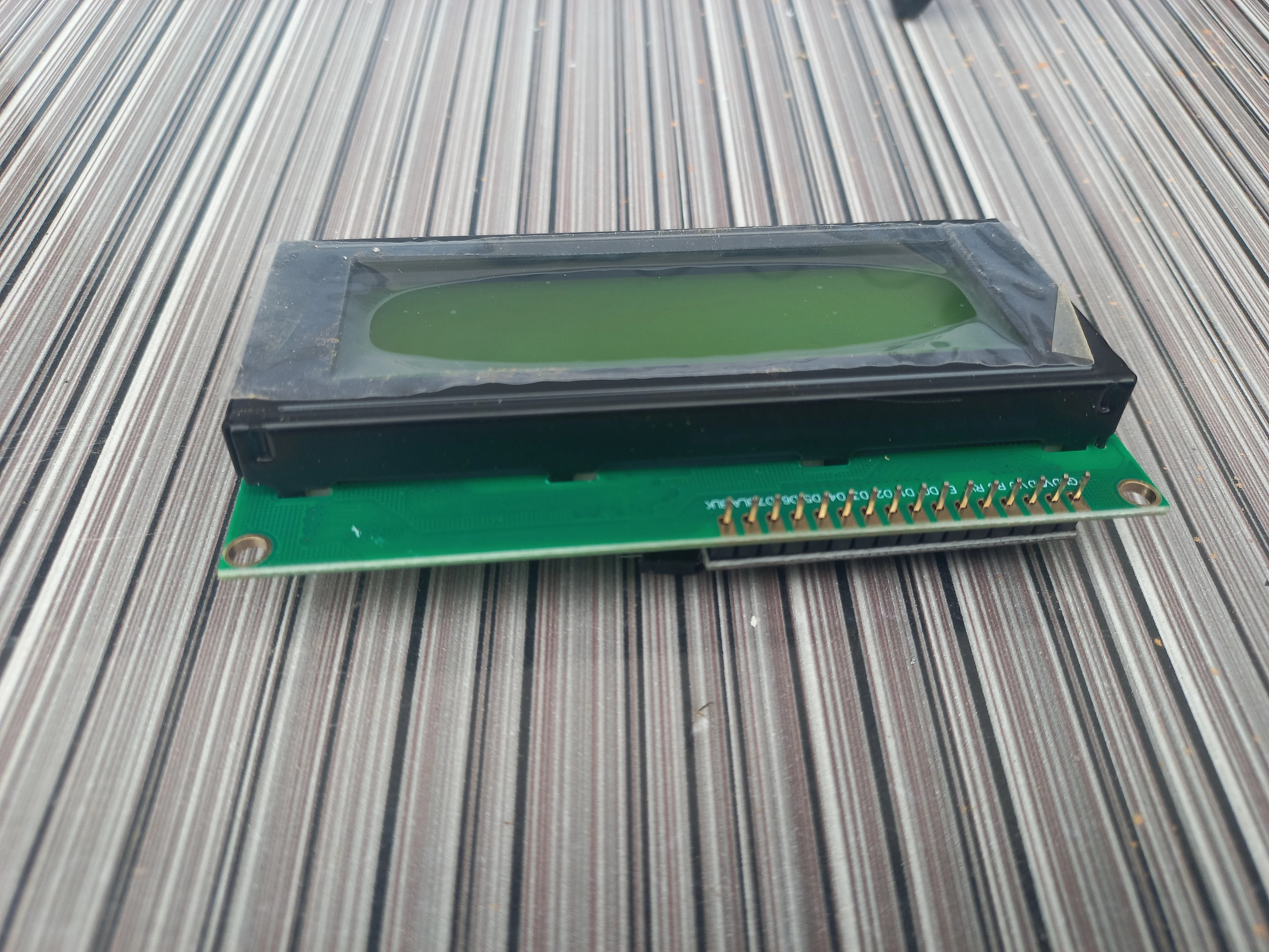
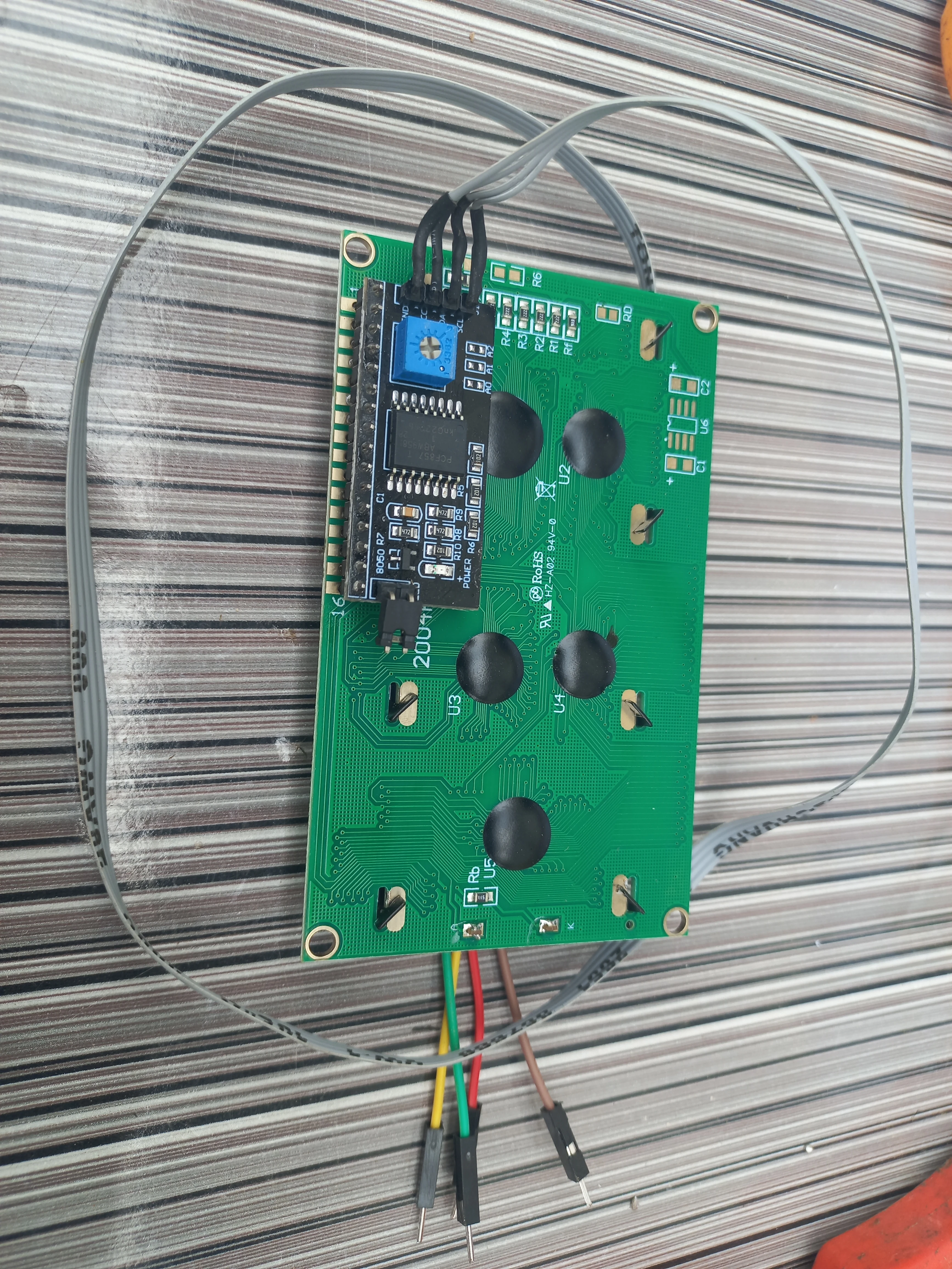
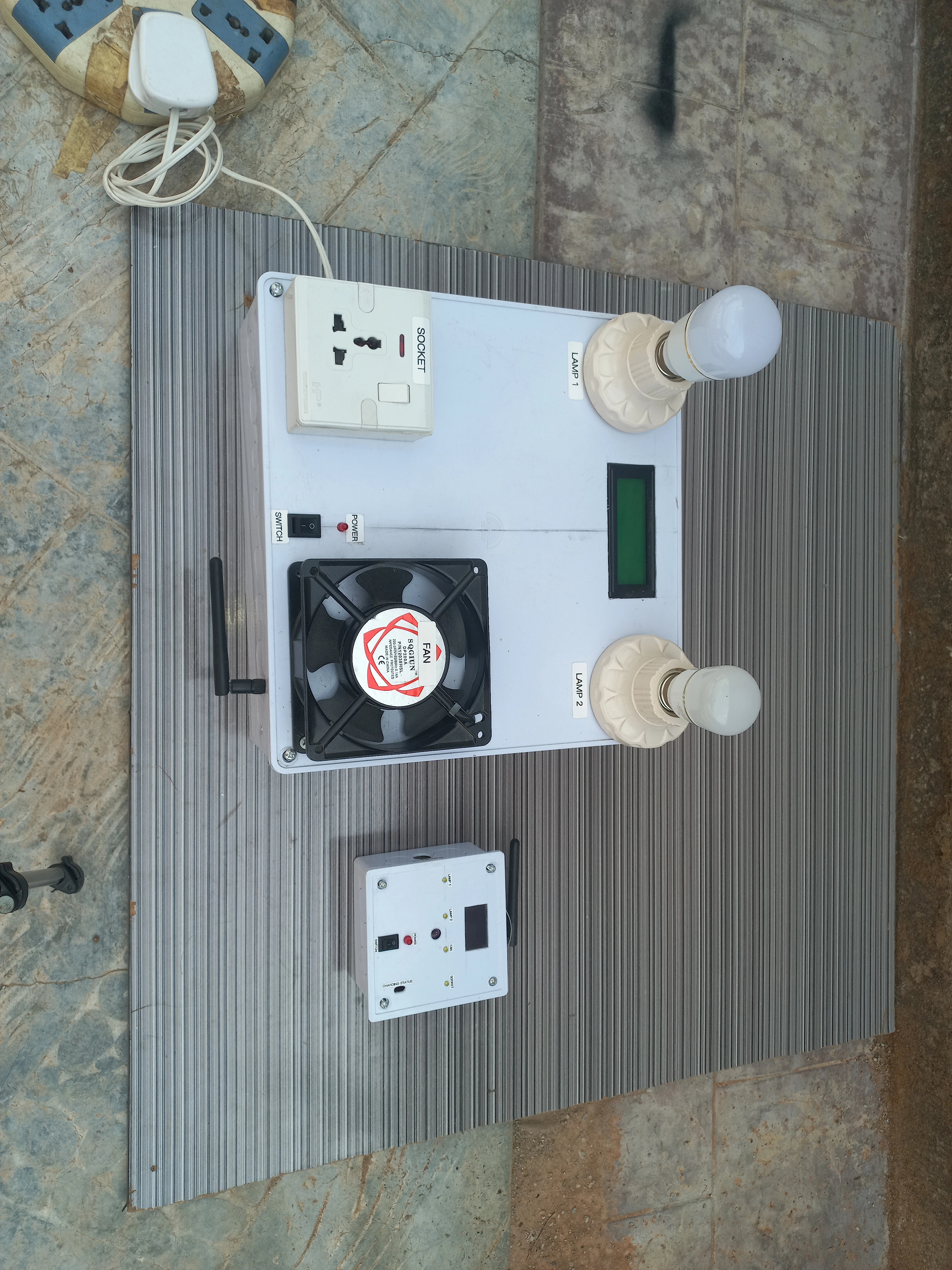
| 20x4 I2C LCD | Character LCD, I2C backpack 0x27, 5V | 1 | SMART CONTROL dashboard on receiver |
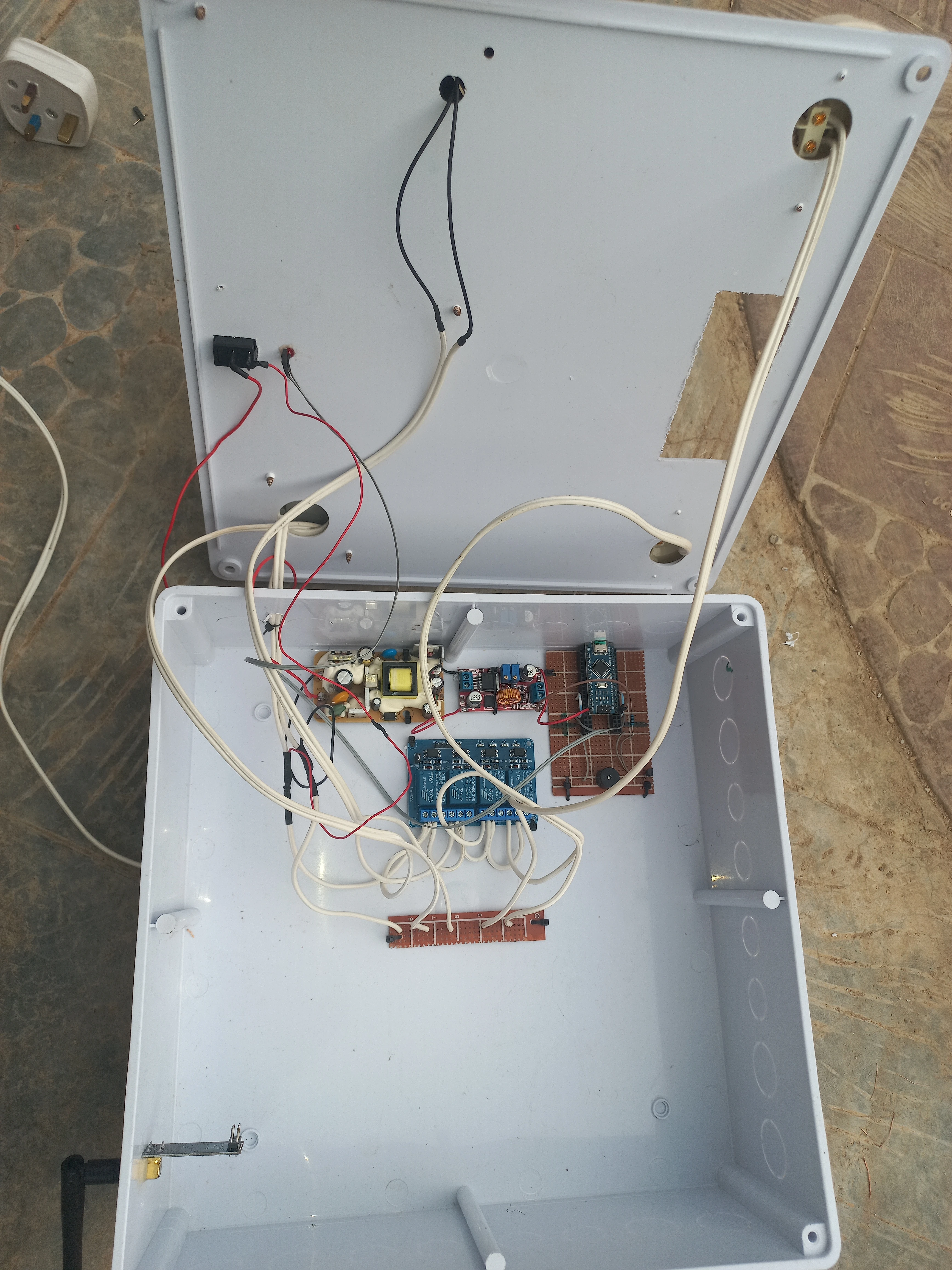
| 4-Channel Relay Module | 5V active-LOW, 250VAC/10A contacts | 1 | Switch Fan, Socket, Lamp 1, Lamp 2 |
| Buzzer | 5V passive/active, D2 | 1 | Audible feedback on command received |
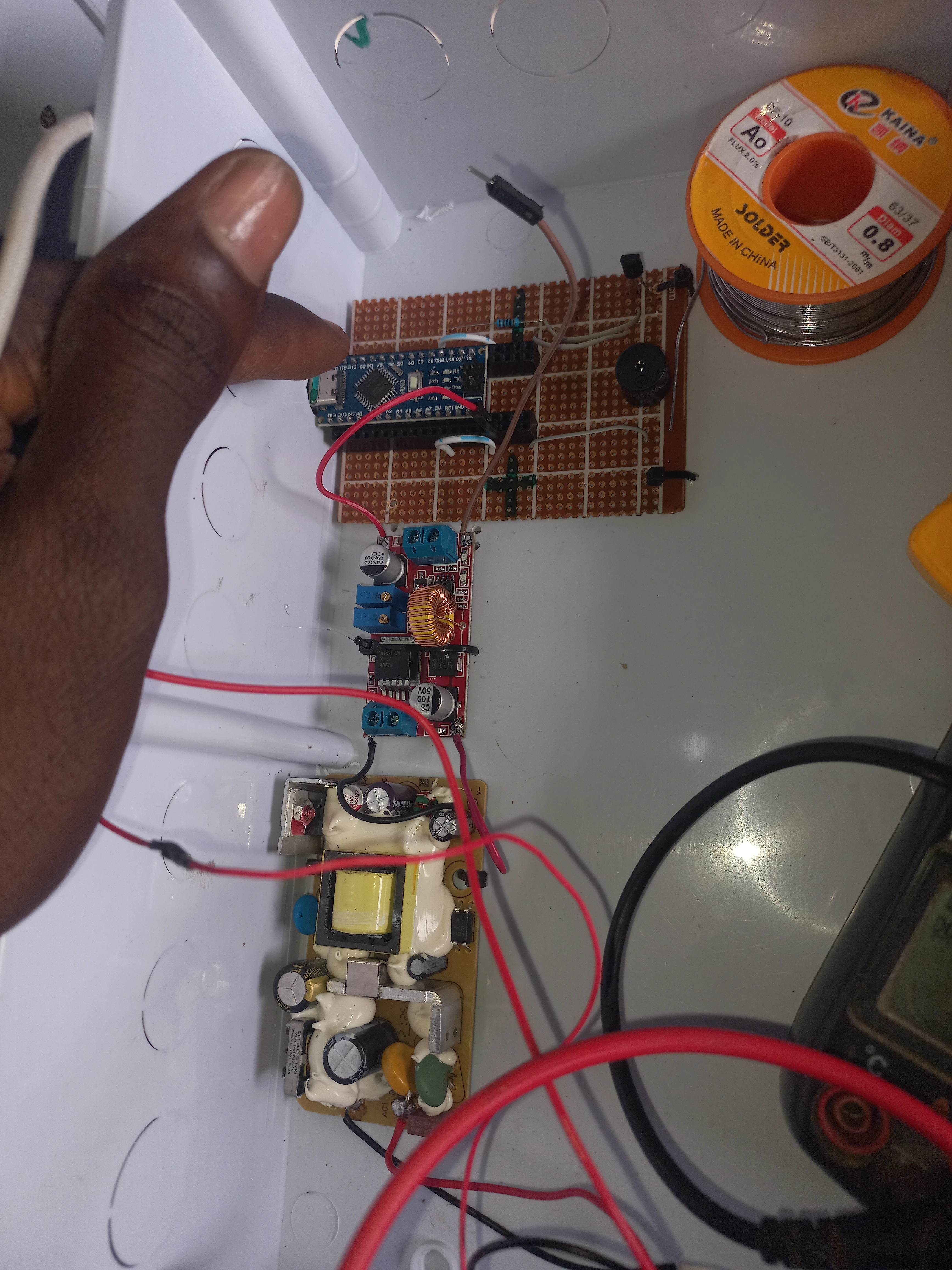
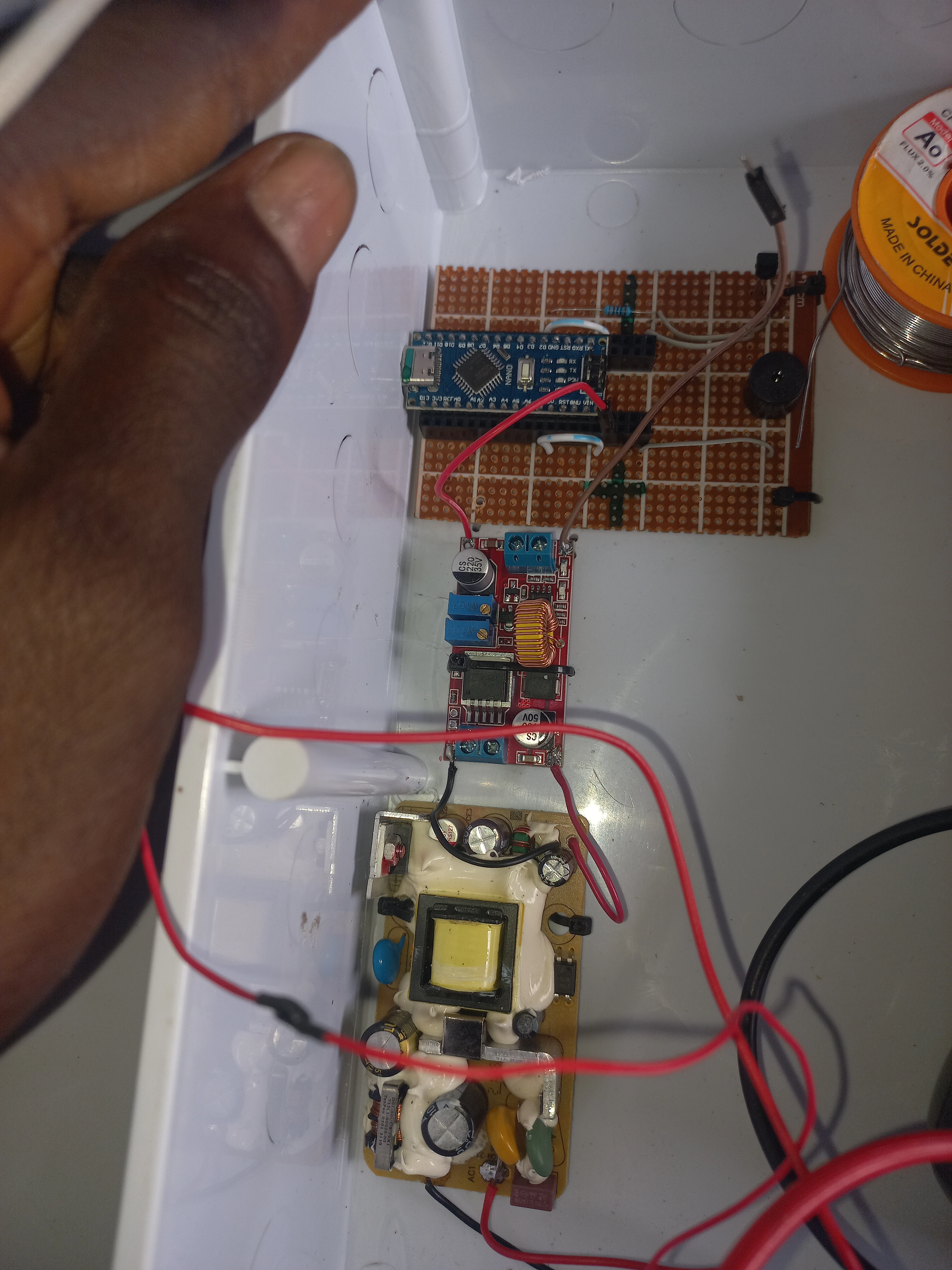
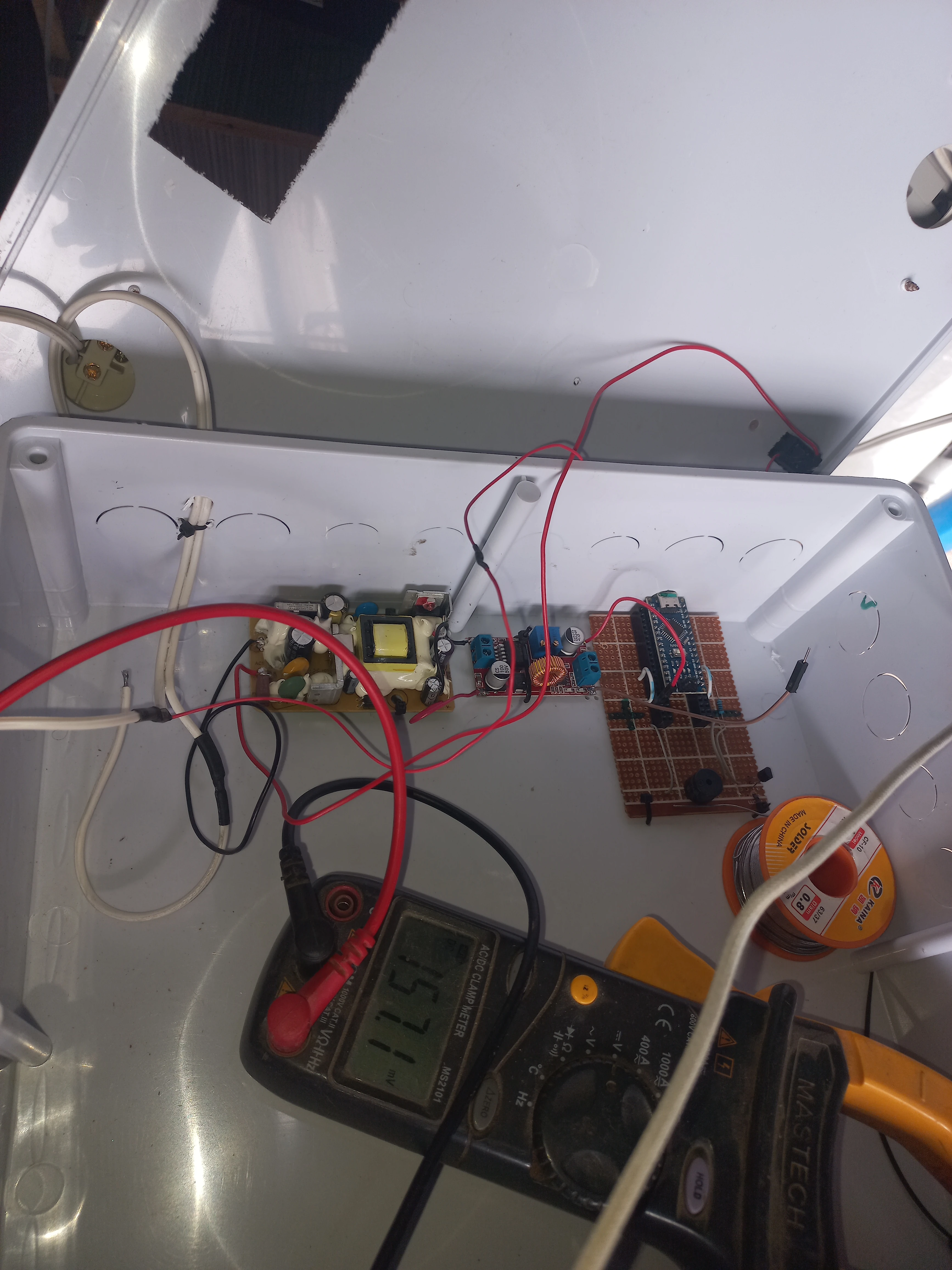
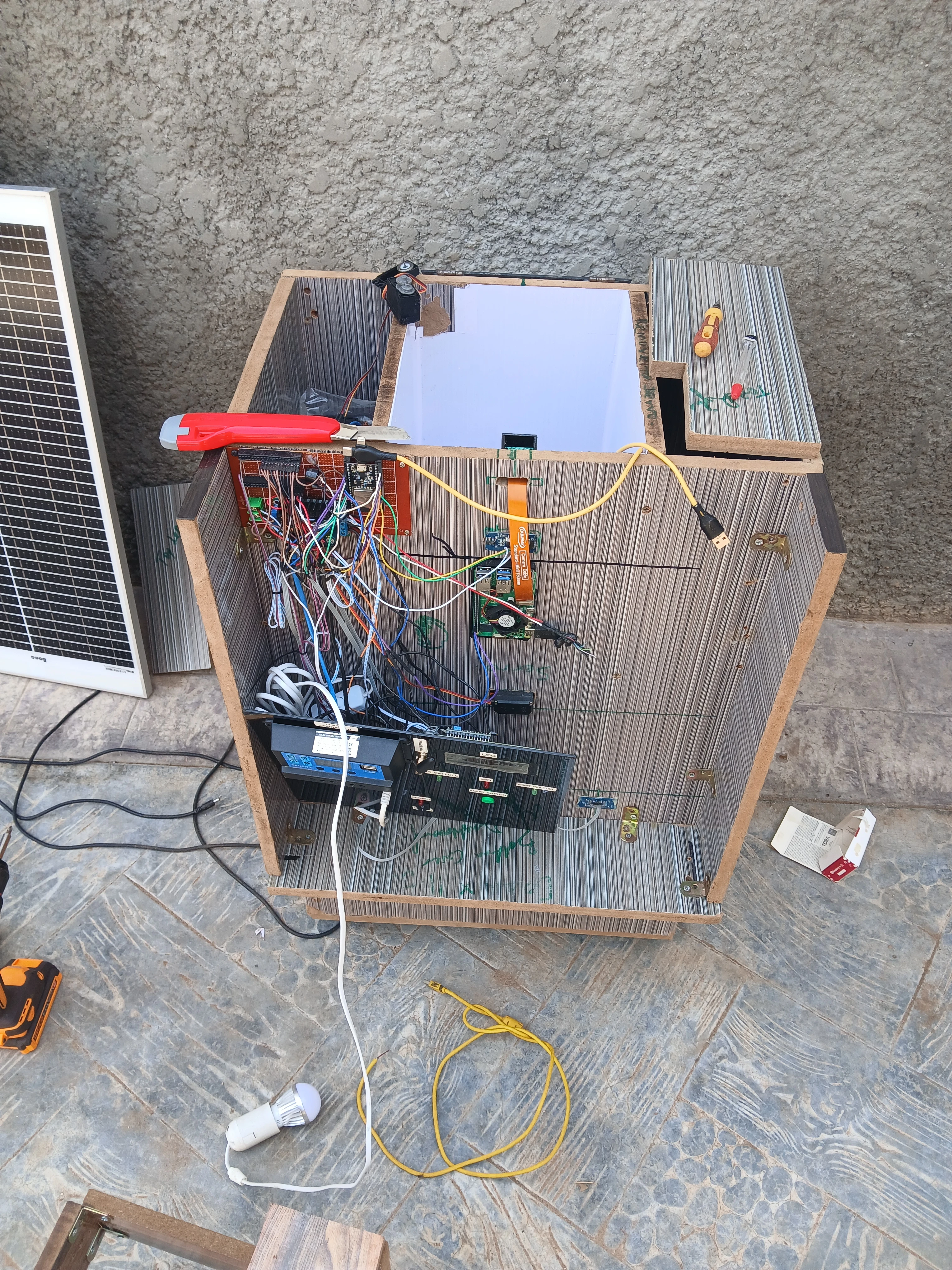
| LM2596 Buck Converter | Input 4-40V, output adjustable, up to 3A | 1 | Step-down 12V to 5V for receiver logic |
| AC-DC Power Supply | 230VAC to 12VDC, bare PCB module | 1 | Mains power for receiver unit |
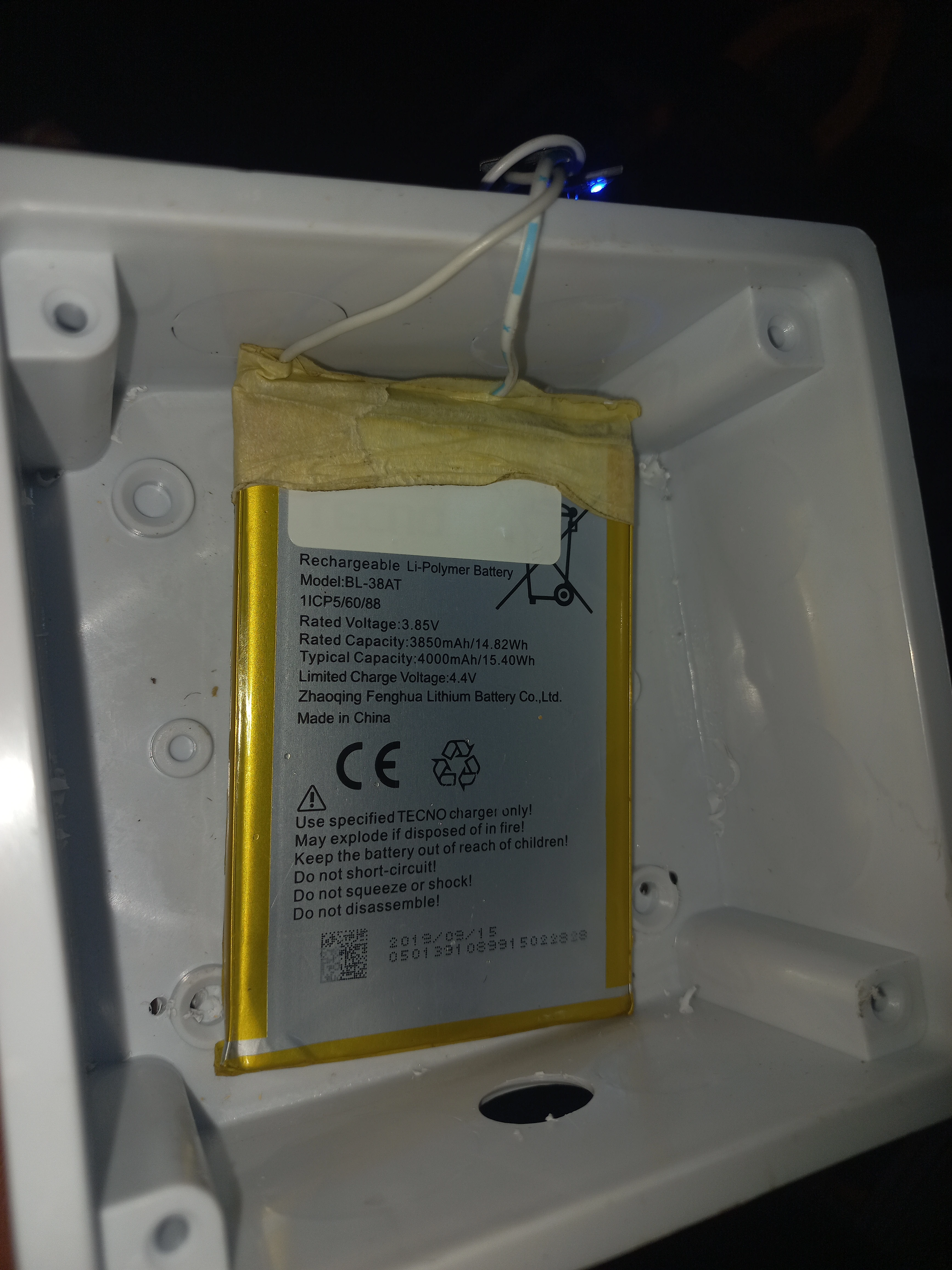
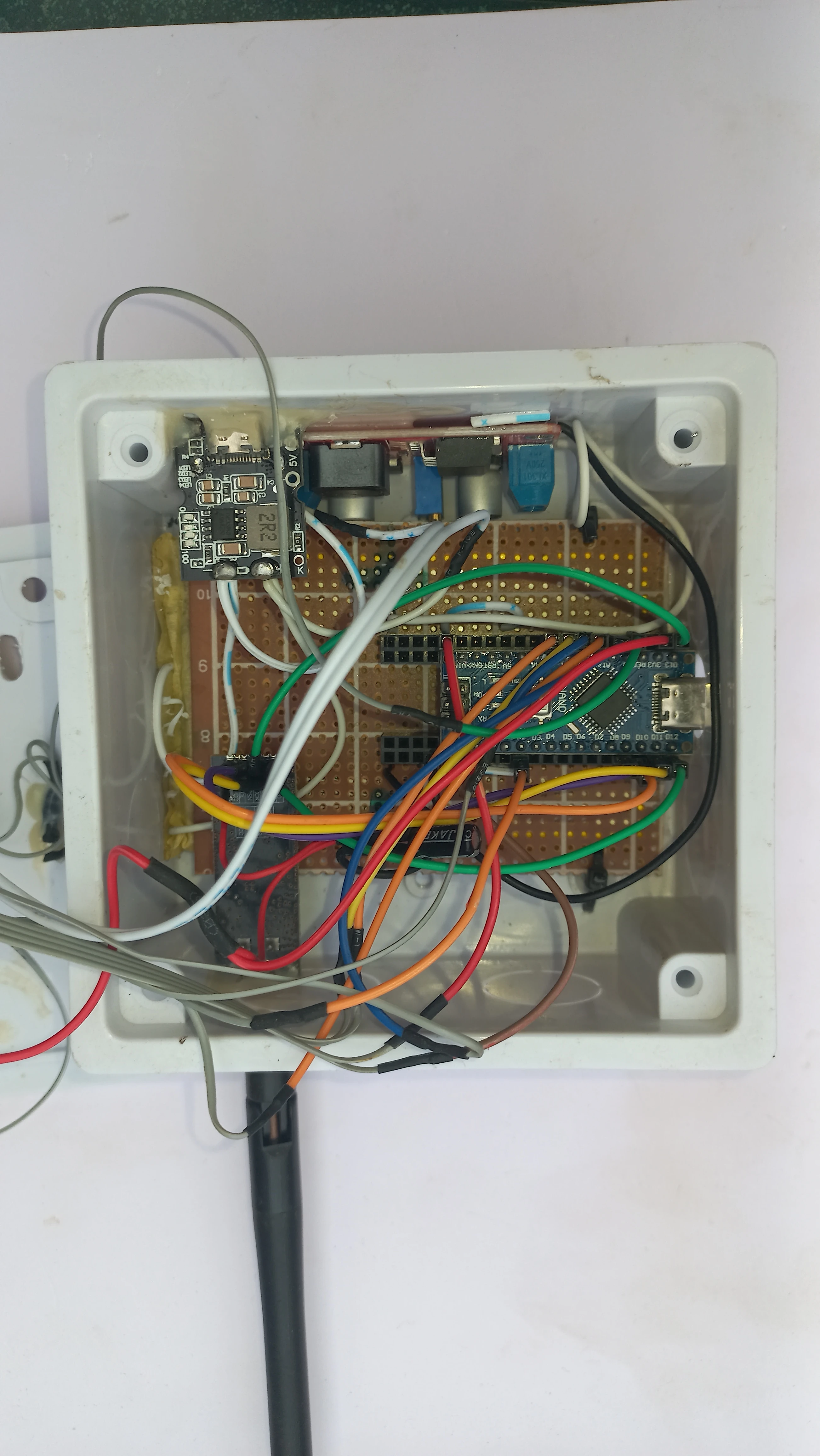
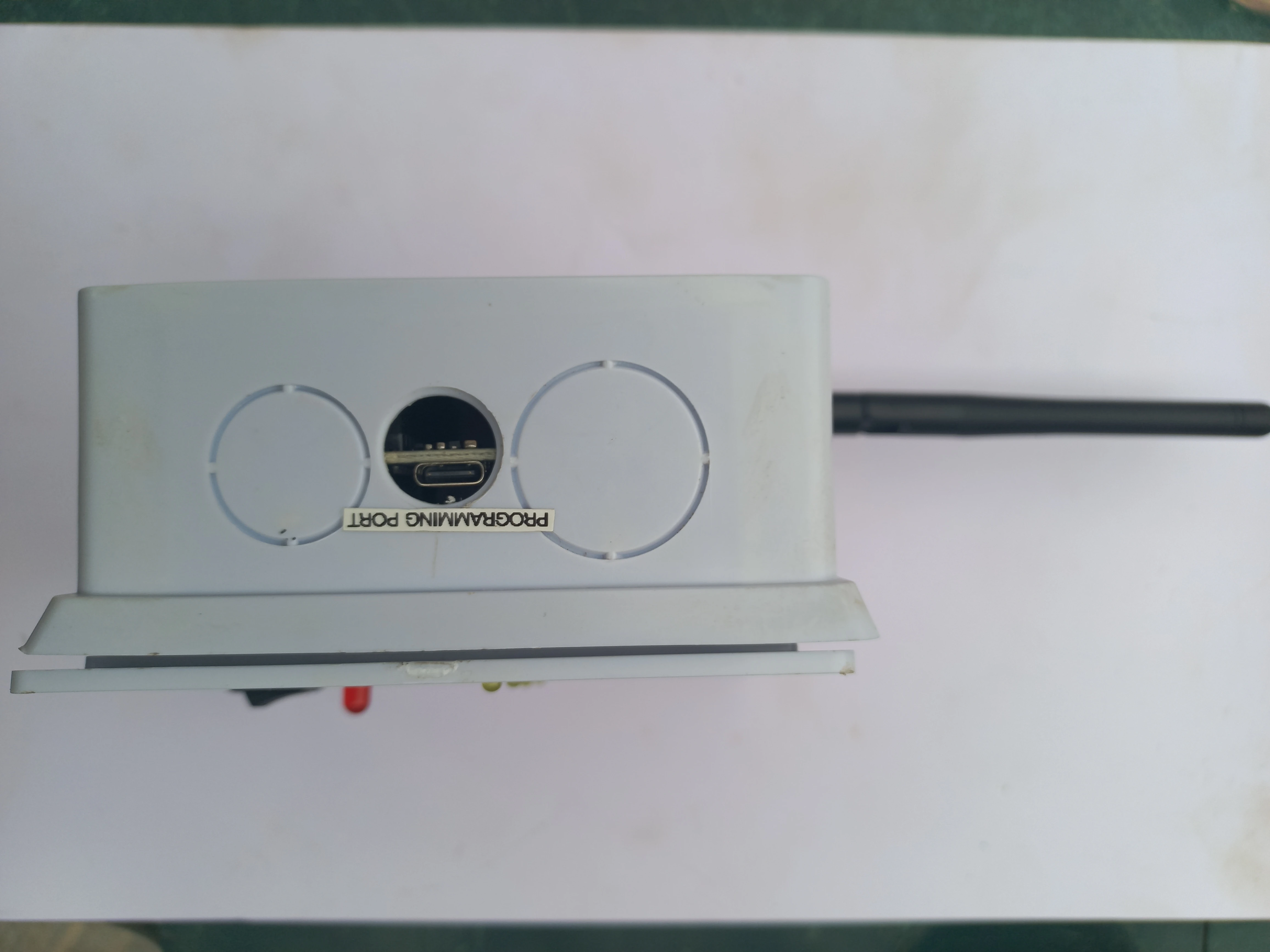
| TP4056 Charger Module | 1A Li-Po/Li-Ion charger, USB-C input | 1 | Transmitter battery charging circuit |
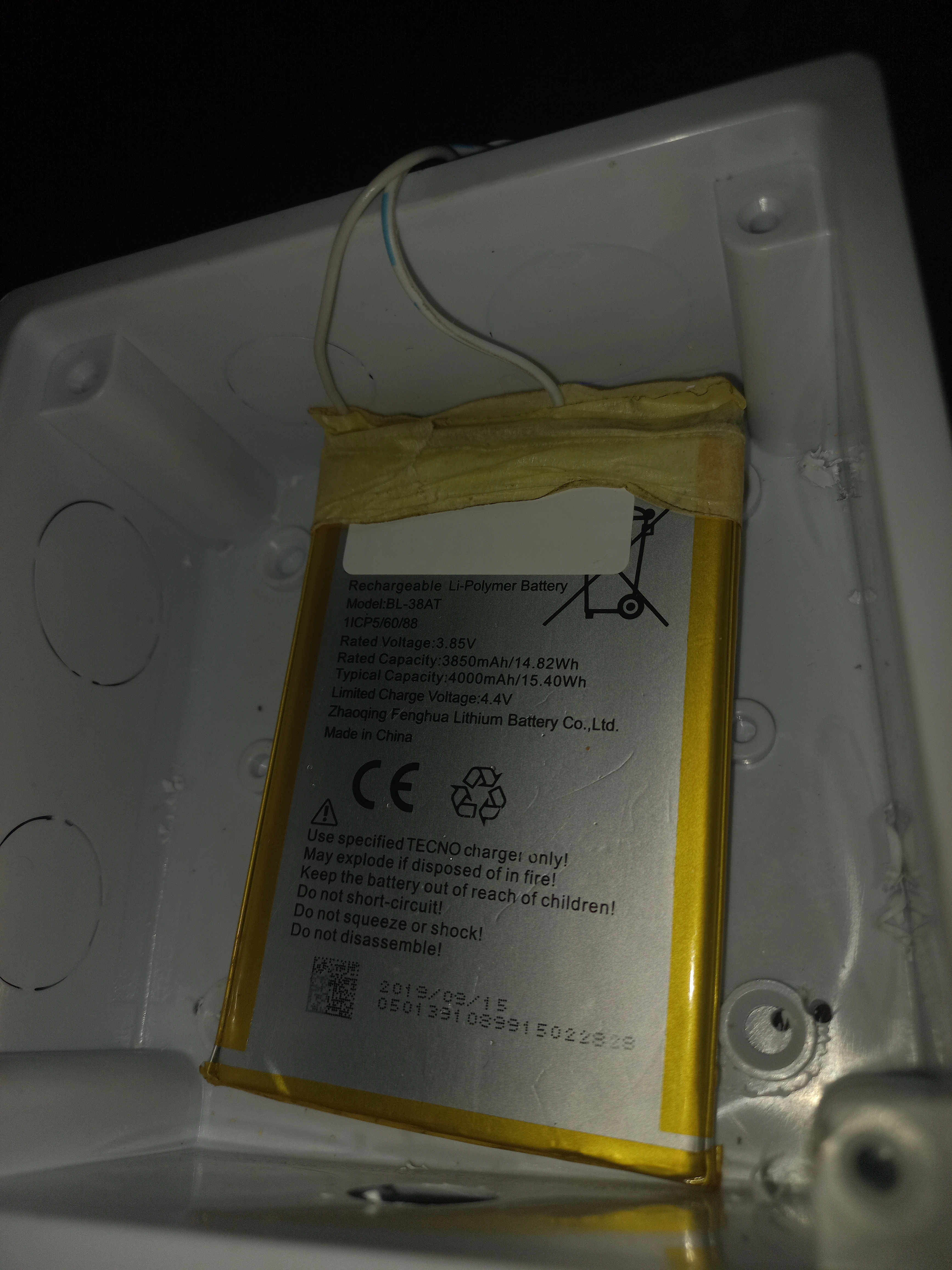
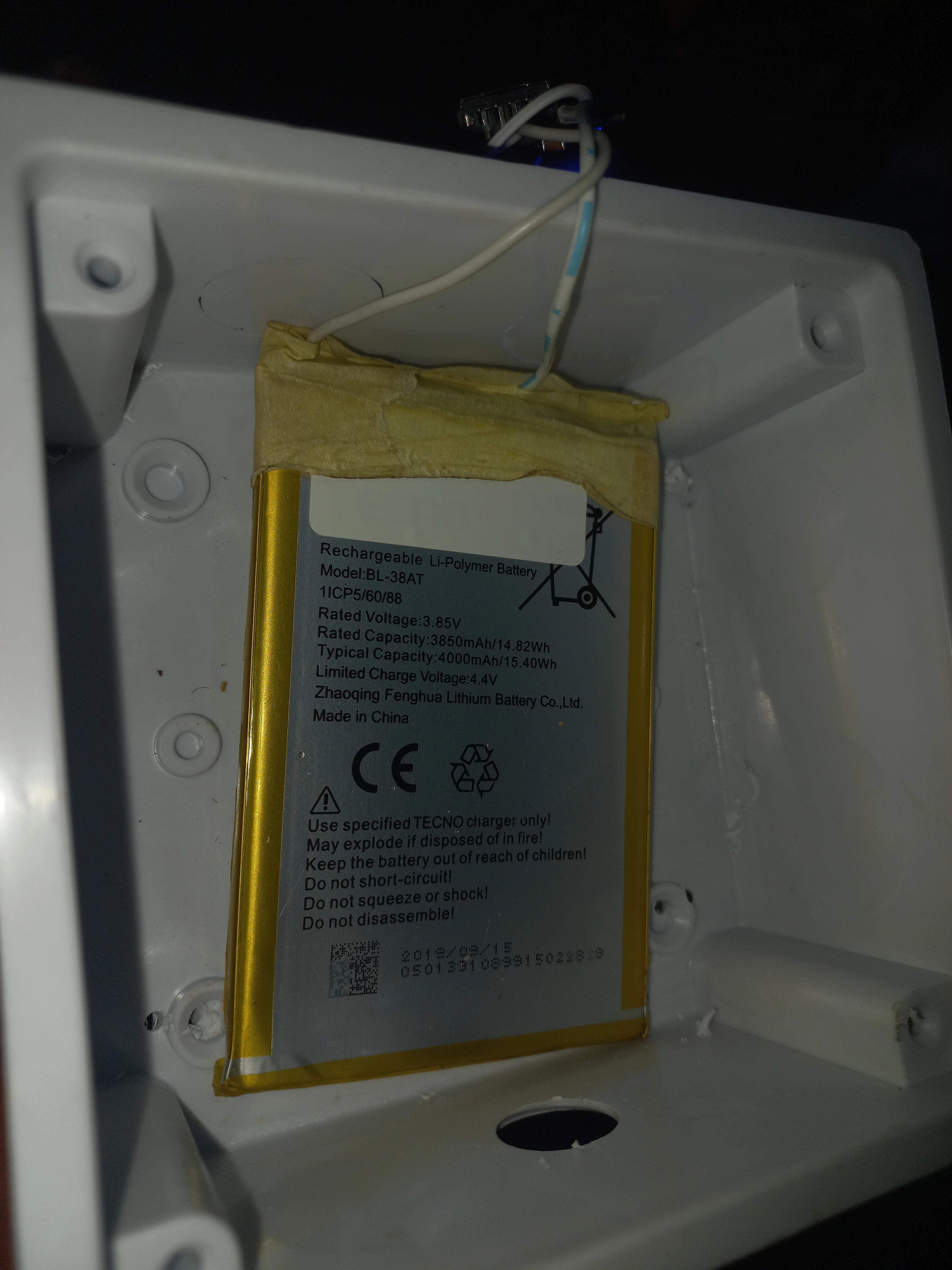
| Li-Polymer Battery | Tecno BL-38AT, 3.85V, 3850mAh / 14.82Wh | 1 | Transmitter portable power source |
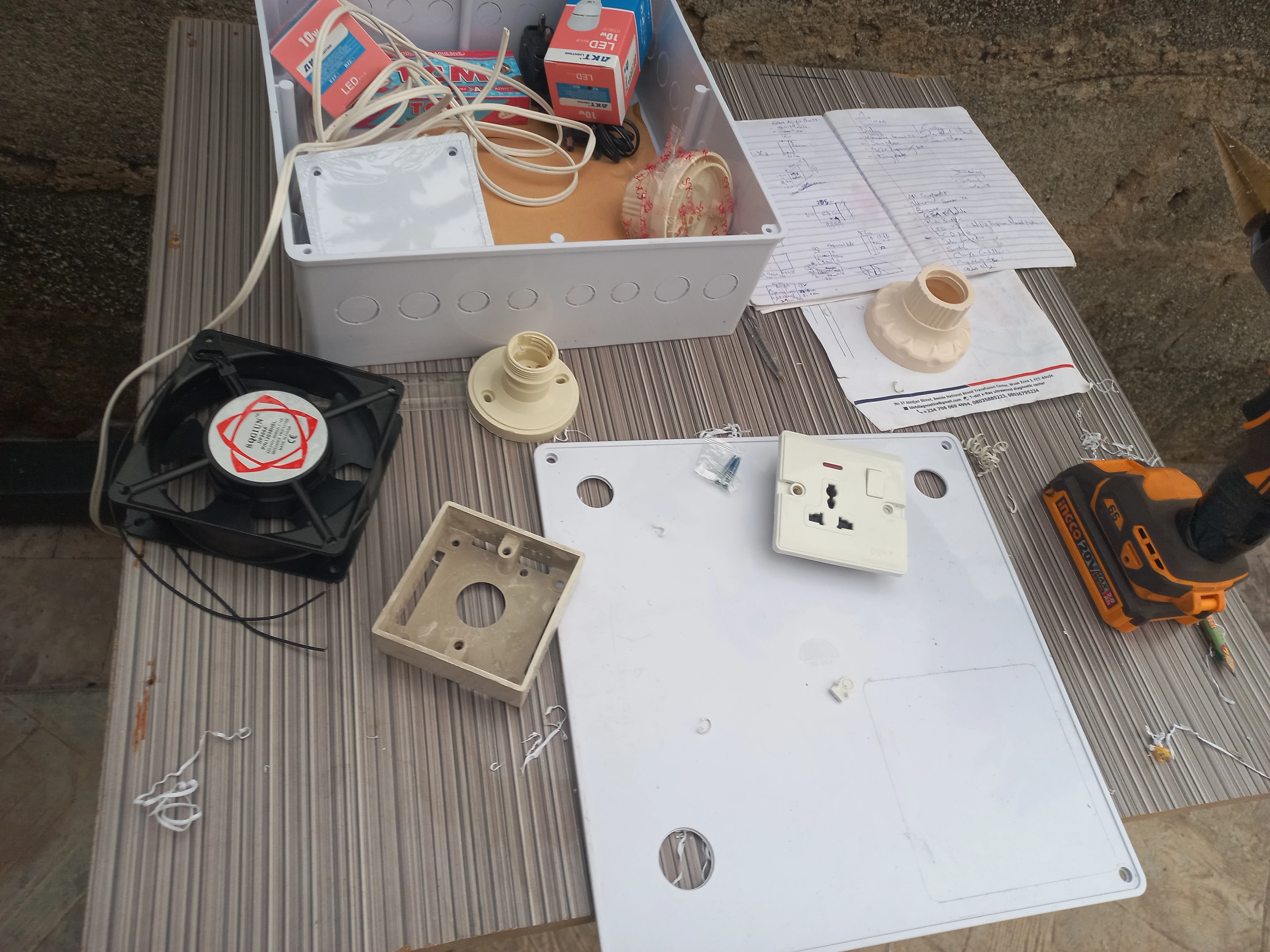
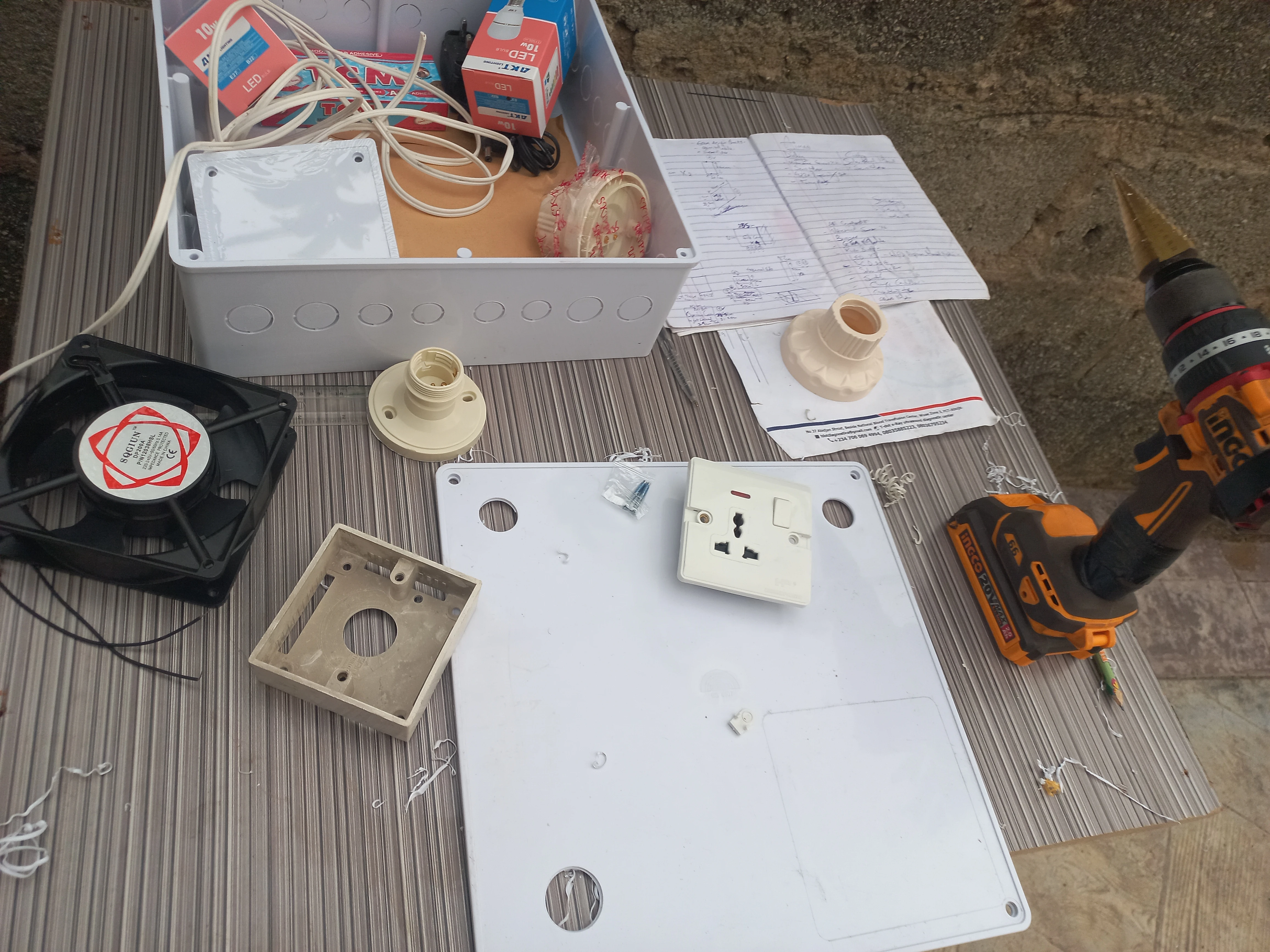
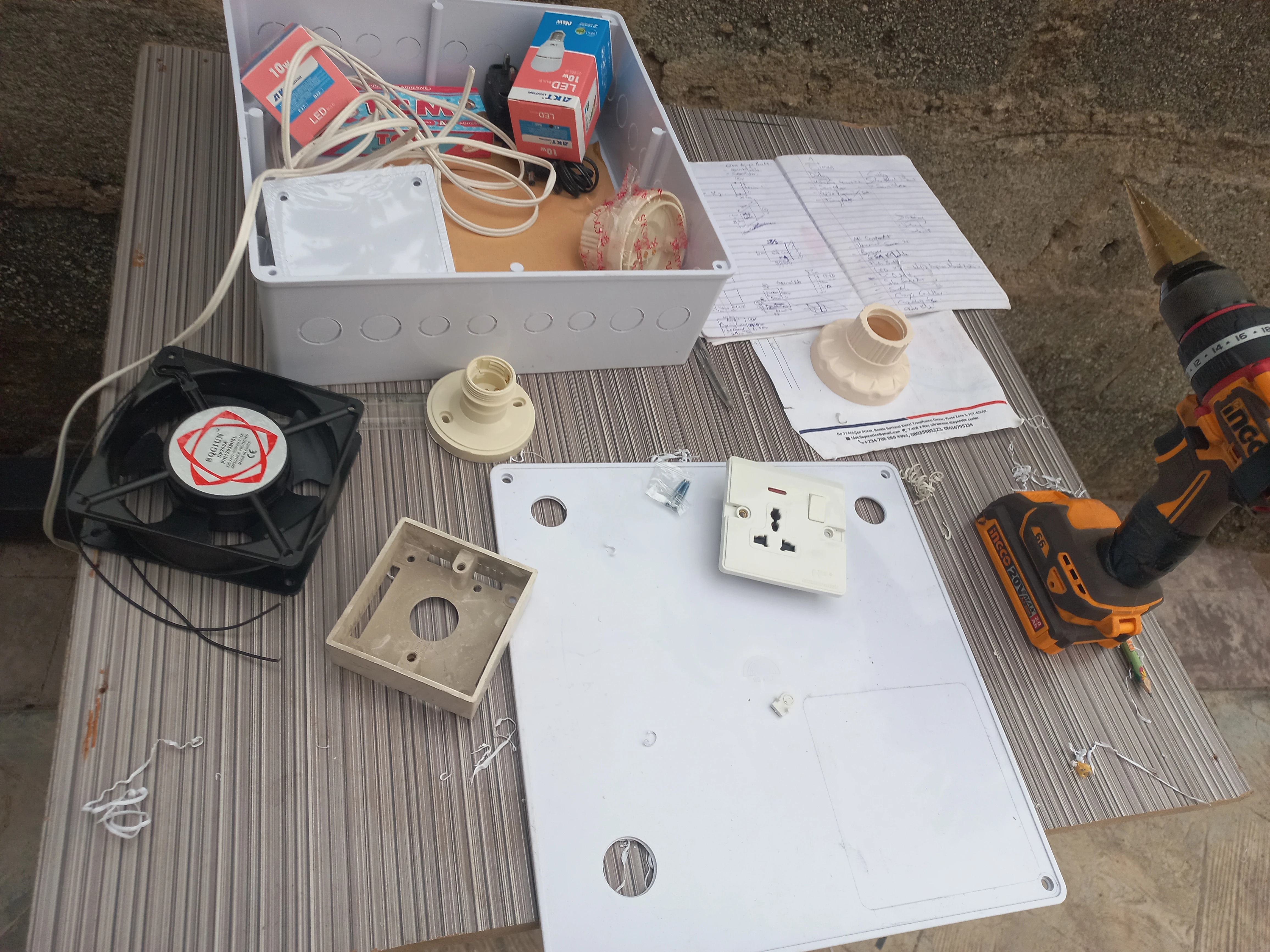
| 120mm Fan | AC fan, EQGIUN brand, 2-wire | 1 | Controlled load on receiver panel |
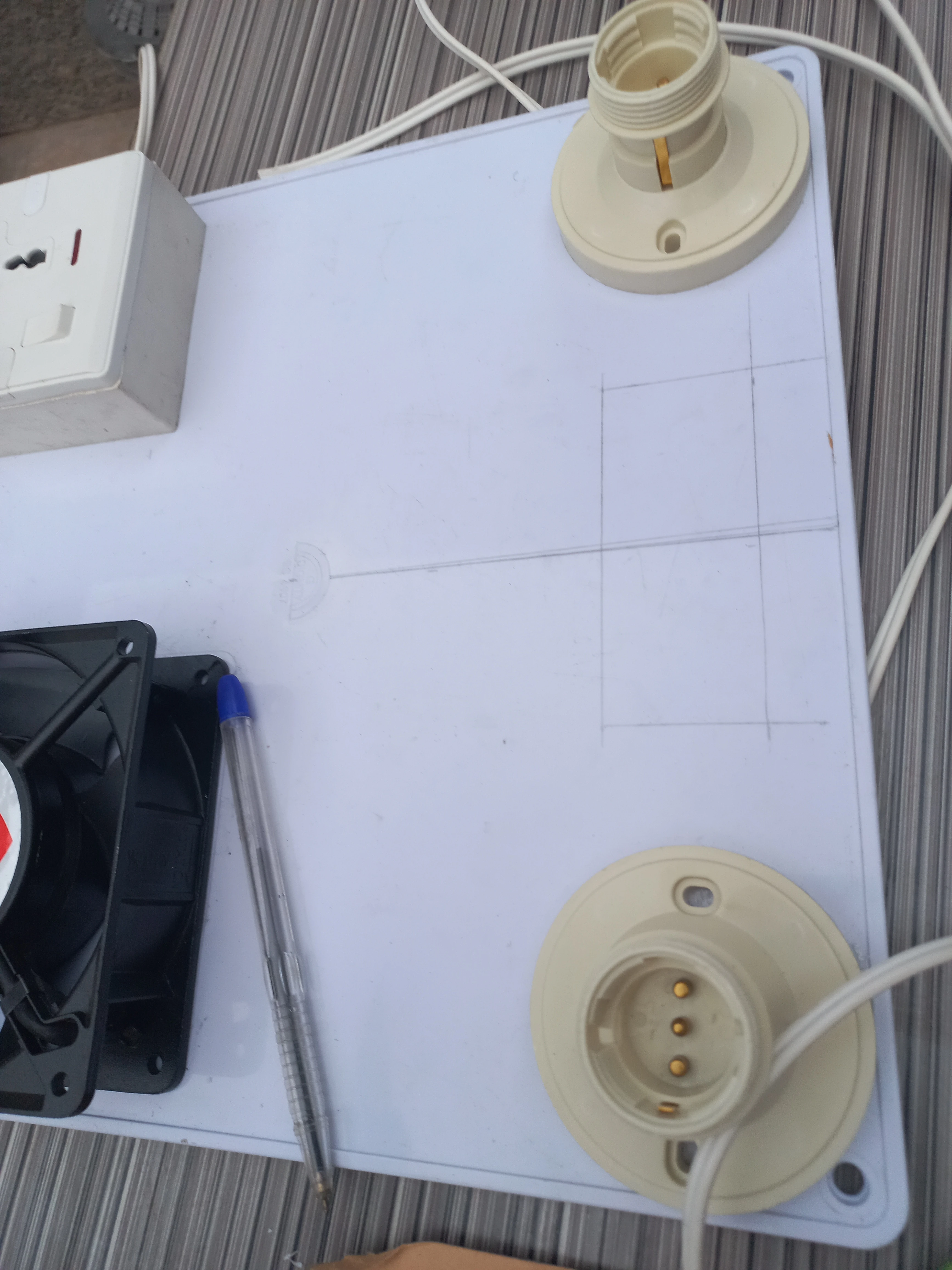
| E27 Lamp Holders | Ceiling-mount base type, with LED bulbs | 2 | Lamp 1 and Lamp 2 controlled loads |
| Universal Mains Socket | 3-pin/2-pin universal, wall-mount box type | 1 | Socket controlled load on receiver panel |
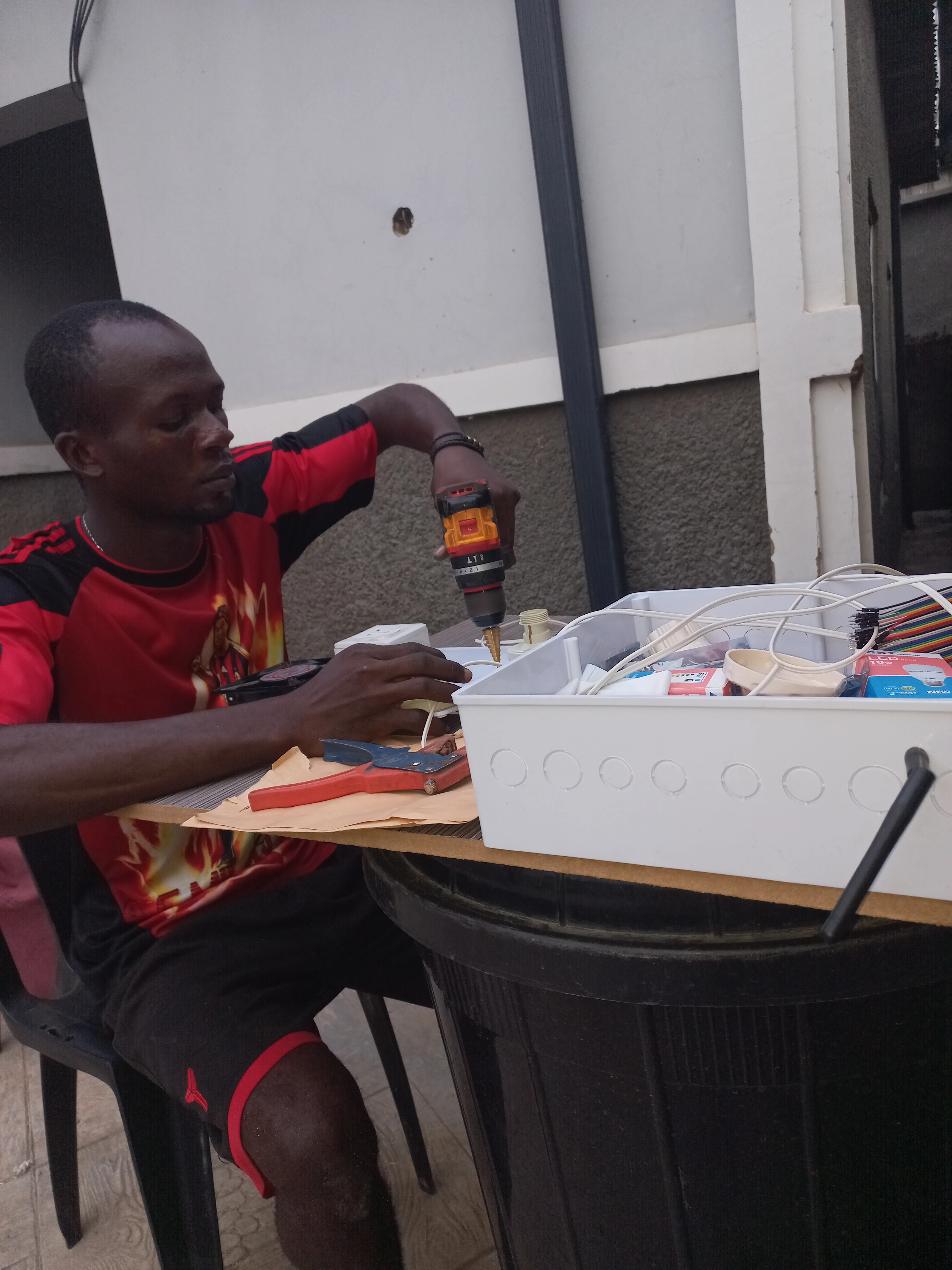
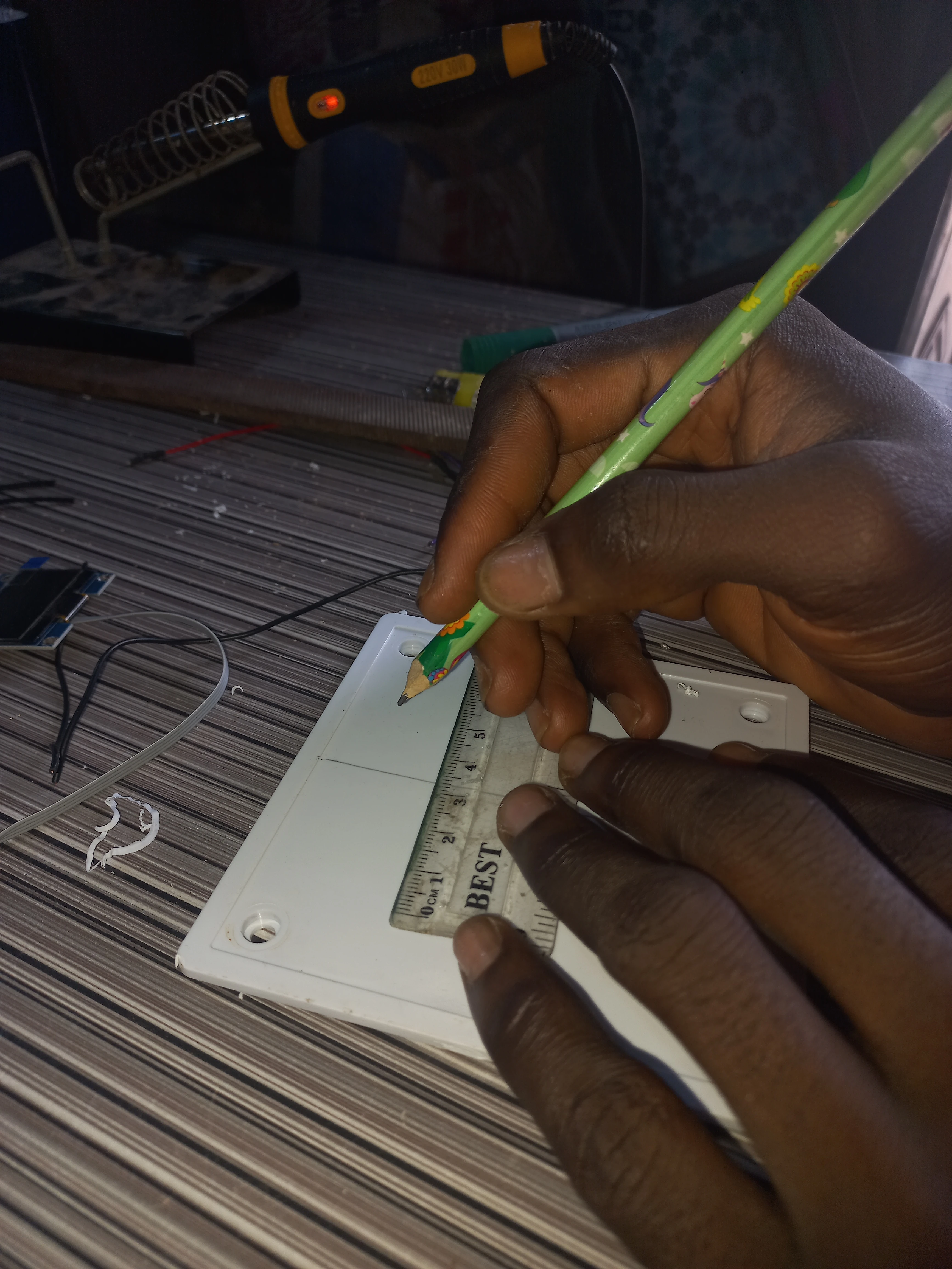
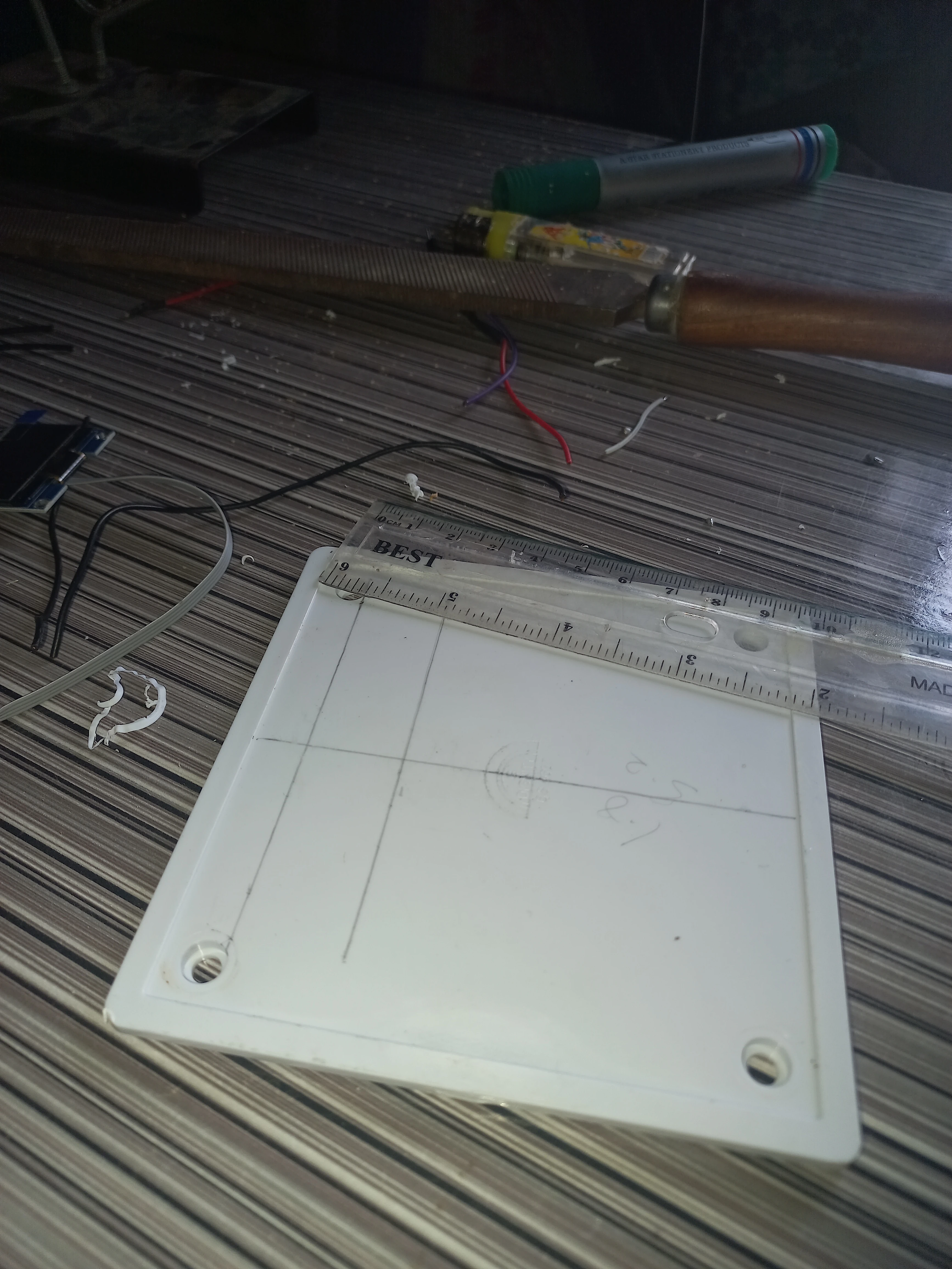
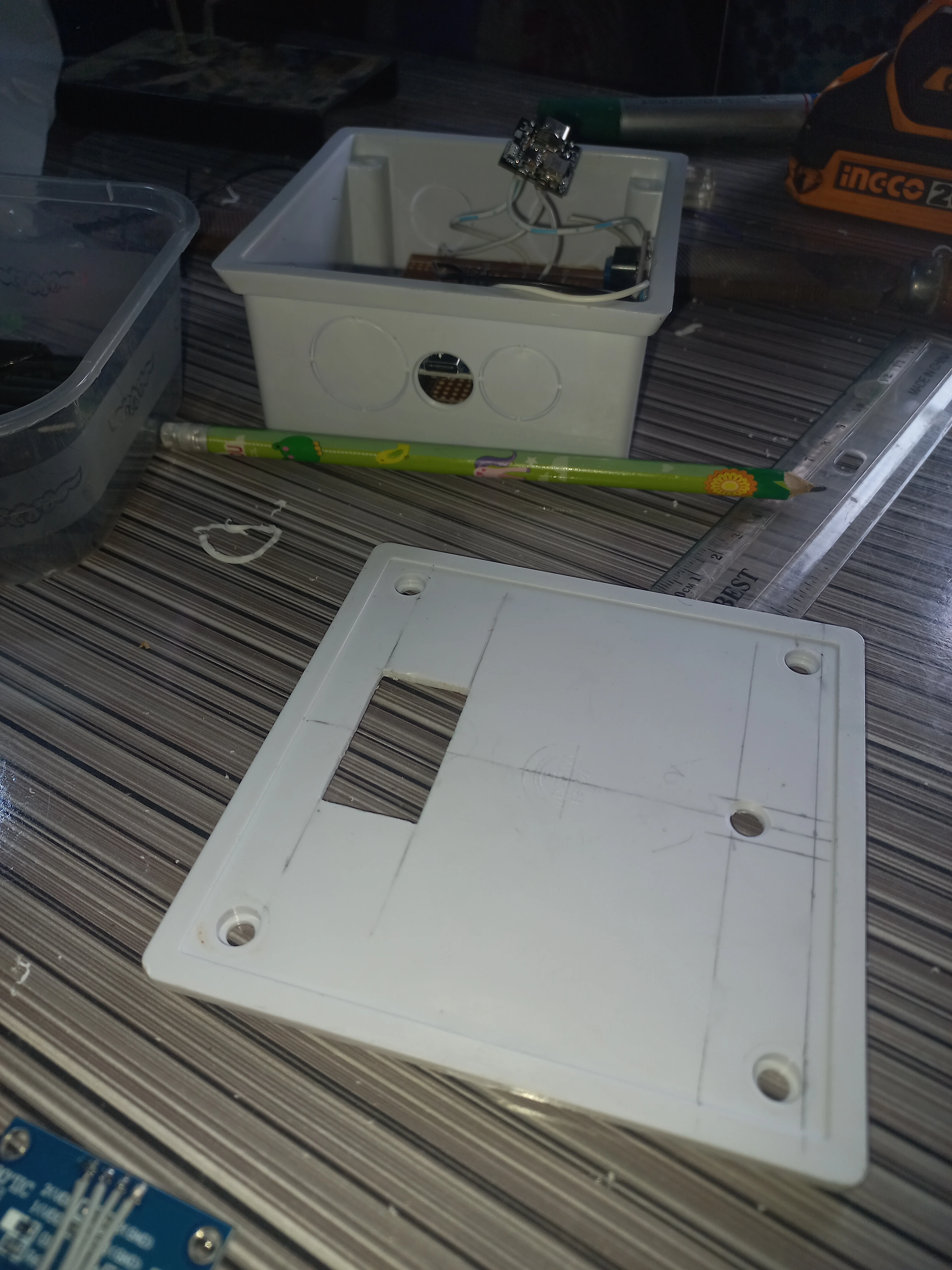
| White Plastic Junction Boxes | Various sizes: small (transmitter), large flat panel (receiver) | 2 | Enclosures for both units |
| Yellow LEDs (5mm) | 5V, with current-limiting resistors | 4 | Appliance state indicators on transmitter face |
| Red LED (5mm) | 5V, with resistor | 1 | Power-ON indicator on transmitter face |
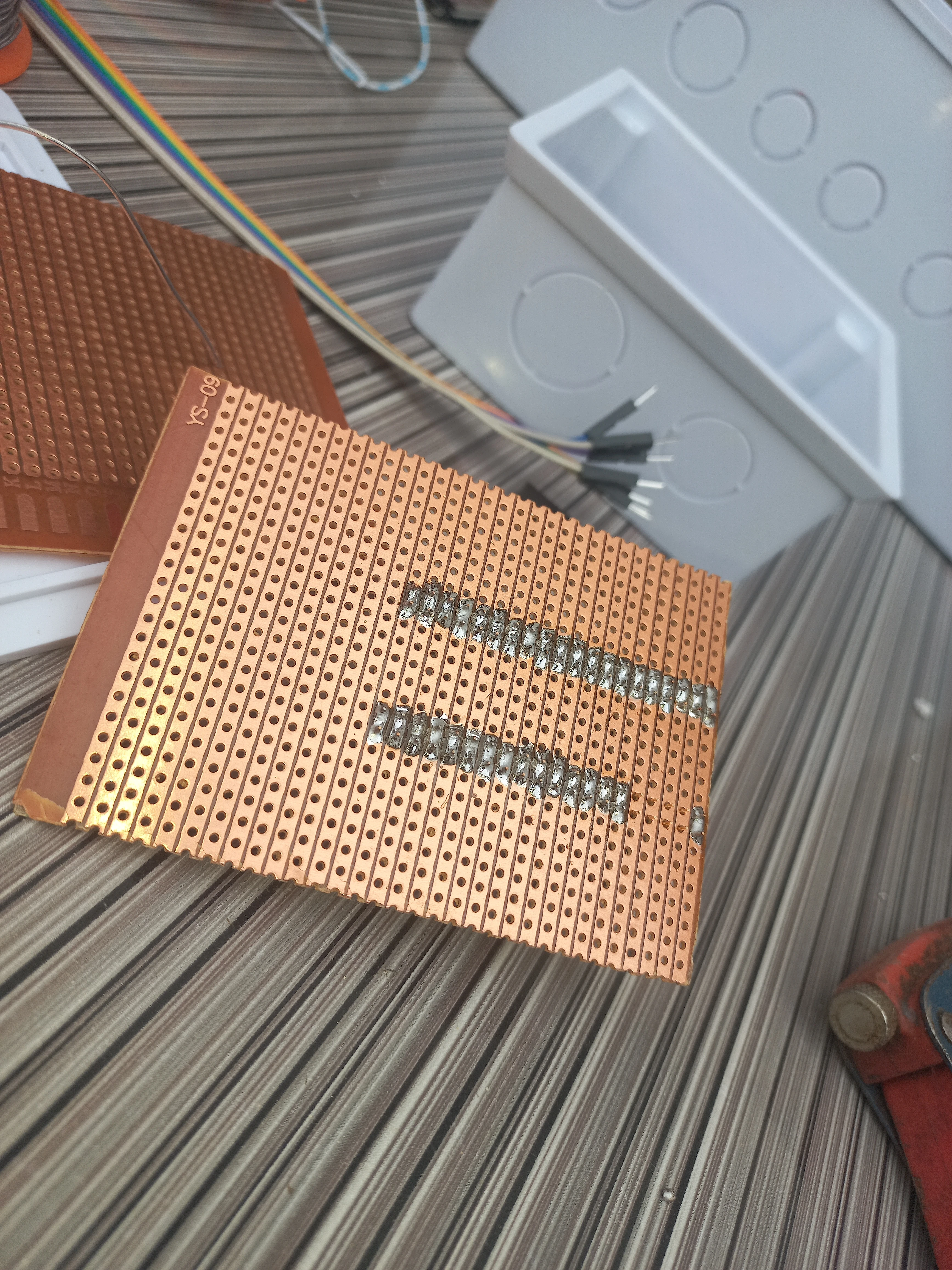
| Veroboard / Perfboard | Standard copper-strip single-sided | 2 | Main circuit assembly boards |
| Toggle Switch | SPST rocker, panel-mount | 2 | Power switches on both units |
| Pin | Connected To | Function |
|---|---|---|
| D9 (CE) | NRF24L01 CE | Chip Enable for RF module |
| D10 (CSN) | NRF24L01 CSN | SPI Chip Select for RF module |
| D11 (MOSI) | NRF24L01 MOSI | SPI data out |
| D12 (MISO) | NRF24L01 MISO | SPI data in |
| D13 (SCK) | NRF24L01 SCK | SPI clock |
| A4 (SDA) | APDS9960 SDA + OLED SDA | I2C data bus |
| A5 (SCL) | APDS9960 SCL + OLED SCL | I2C clock bus |
| A0 | Socket status LED + LED state | Socket appliance indicator |
| A1 | Fan status LED + LED state | Fan appliance indicator |
| A2 | Lamp 2 status LED + LED state | Lamp 2 appliance indicator |
| A3 | Lamp 1 status LED + LED state | Lamp 1 appliance indicator |
| 3.3V | NRF24L01 VCC + APDS9960 VCC | 3.3V power rail |
| 5V | OLED VCC | 5V power rail |
| GND | All module GND | Common ground |
| Pin | Connected To | Function |
|---|---|---|
| D9 (CE) | NRF24L01 CE | Chip Enable for RF module |
| D10 (CSN) | NRF24L01 CSN | SPI Chip Select |
| D11 (MOSI) | NRF24L01 MOSI | SPI data out |
| D12 (MISO) | NRF24L01 MISO | SPI data in |
| D13 (SCK) | NRF24L01 SCK | SPI clock |
| D2 | Buzzer | Audible command-received beep |
| A4 (SDA) | LCD I2C SDA | I2C data to LCD backpack |
| A5 (SCL) | LCD I2C SCL | I2C clock to LCD backpack |
| A0 | Relay IN1 (Socket) | Active-LOW relay for socket |
| A1 | Relay IN2 (Fan) | Active-LOW relay for fan |
| A2 | Relay IN3 (Lamp 2) | Active-LOW relay for Lamp 2 |
| A3 | Relay IN4 (Lamp 1) | Active-LOW relay for Lamp 1 |
| 3.3V | NRF24L01 VCC | 3.3V for RF module |
| 5V | Relay VCC + LCD VCC | 5V power rail |
| GND | All module GND | Common ground |
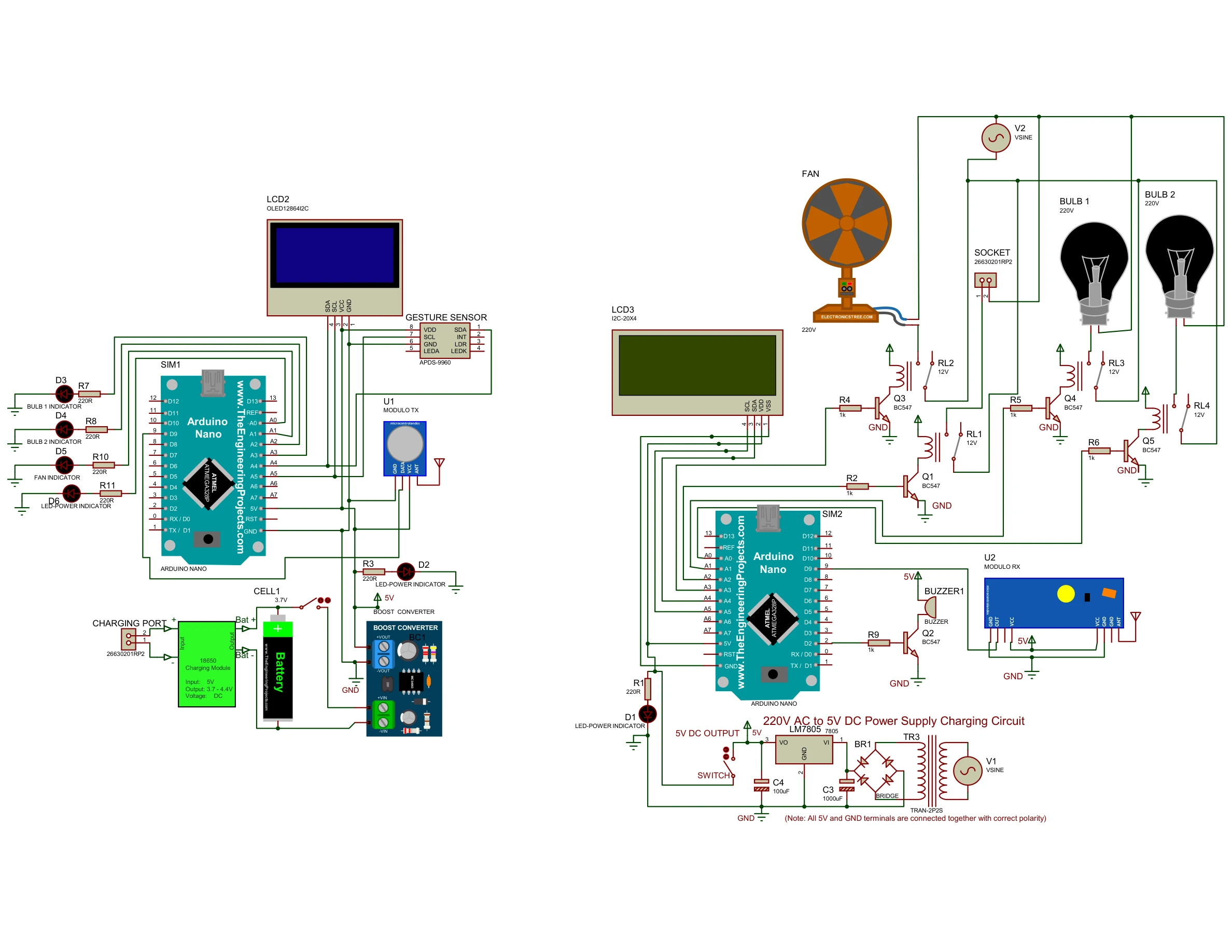
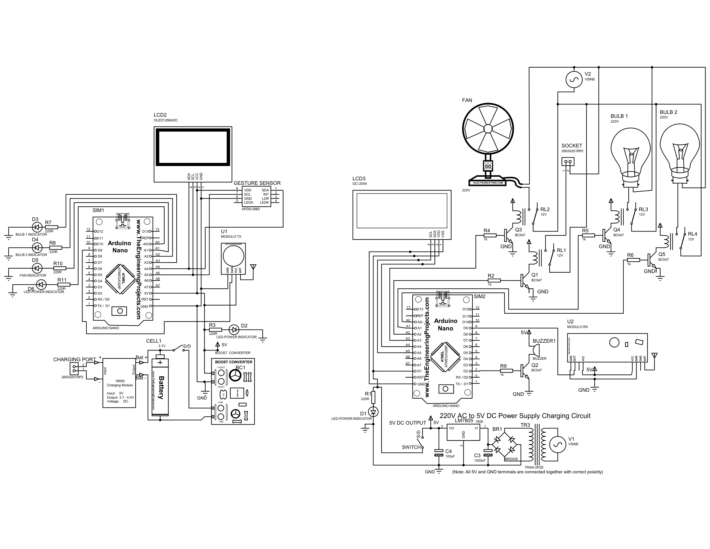
Full Proteus circuit diagram showing both units: the transmitter Arduino Nano with APDS-9960 gesture sensor, SH1106 OLED, NRF24L01 TX, TP4056 Li-Ion charger, boost converter, and four status LEDs; and the receiver Arduino Nano with NRF24L01 RX, 4-channel BC547 relay driver circuit, 20x4 I2C LCD, buzzer, and a 220V AC to 5V DC LM7805 power supply.
The APDS9960 recognises four gestures. Each gesture toggles the assigned appliance and transmits an explicit command string via NRF24L01:
| Hand Gesture | Command Sent | Appliance | Transmitter OLED Display |
|---|---|---|---|
| Swipe UP | "U ON" / "U OFF" |
Lamp 1 (Relay A3) | Action: SWIPE UP | LAMP 1 | State: ON/OFF |
| Swipe DOWN | "D ON" / "D OFF" |
Lamp 2 (Relay A2) | Action: SWIPE DOWN | LAMP 2 | State: ON/OFF |
| Swipe LEFT | "L ON" / "L OFF" |
Fan (Relay A1) | Action: SWIPE LEFT | FAN | State: ON/OFF |
| Swipe RIGHT | "R ON" / "R OFF" |
Socket (Relay A0) | Action: SWIPE RIGHT | SOCKET | State: ON/OFF |
Serial: ALL ON |
"ALL ON" |
All four appliances | ALL DEVICES | State: ON |
Serial: ALL OFF |
"ALL OFF" |
All four appliances | ALL DEVICES | State: OFF |
digitalWrite(RELAY_SOCKET, !sSocket). This means
a true appliance state drives the pin LOW to energise the relay coil.
The transmitter loop reads the APDS9960 gesture register, maps the direction to a command string, updates the local LED state and OLED, then fires the NRF24L01 write:
void loop() {
  String cmdStr = "";
  const char* gestureDetected = "NONE";

  // Read gesture from APDS9960
  uint8_t gesture = apds.readGesture();

  if (gesture > 0) {
    if (gesture == APDS9960_UP) {
      stateA3 = !stateA3;                    // Toggle Lamp 1
      cmdStr = stateA3 ? "U ON" : "U OFF";
      gestureDetected = "SWIPE UP";
    } else if (gesture == APDS9960_DOWN) {
      stateA2 = !stateA2;                    // Toggle Lamp 2
      cmdStr = stateA2 ? "D ON" : "D OFF";
      gestureDetected = "SWIPE DOWN";
    } else if (gesture == APDS9960_LEFT) {
      stateA1 = !stateA1;                    // Toggle Fan
      cmdStr = stateA1 ? "L ON" : "L OFF";
      gestureDetected = "SWIPE LEFT";
    } else if (gesture == APDS9960_RIGHT) {
      stateA0 = !stateA0;                    // Toggle Socket
      cmdStr = stateA0 ? "R ON" : "R OFF";
      gestureDetected = "SWIPE RIGHT";
    }
  }

  if (cmdStr.length() > 0) {
    // Update LED outputs to mirror appliance state
    digitalWrite(A3, stateA3);
    digitalWrite(A2, stateA2);
    digitalWrite(A1, stateA1);
    digitalWrite(A0, stateA0);

    // Pack into fixed 10-byte array (avoids garbage from memory)
    char payload[10] = { 0 };
    cmdStr.toCharArray(payload, sizeof(payload));

    // Transmit via NRF24L01 (15 retries set in setup for relay noise)
    radio.write(&payload, sizeof(payload));

    // Update OLED with gesture name, device, and new state
    showOLED(gestureDetected, device, status);
    delay(200);
  }
}The receiver listens on the NRF24L01 pipe. On each received payload, it parses the command, updates relay outputs (active-LOW), refreshes the 20x4 LCD, and beeps the buzzer:
void loop() {
  if (radio.available()) {
    char payload[10] = {0};
    radio.read(&payload, sizeof(payload));

    String cmdStr(payload);
    cmdStr.trim();

    const char* line1 = "";
    const char* line2 = "";
    bool validCommand = true;

    if      (cmdStr == "U ON")  { sLamp1 = true;  line1 = "LAMP 1";       line2 = "ON";  }
    else if (cmdStr == "U OFF") { sLamp1 = false;  line1 = "LAMP 1";       line2 = "OFF"; }
    else if (cmdStr == "D ON")  { sLamp2 = true;   line1 = "LAMP 2";       line2 = "ON";  }
    else if (cmdStr == "D OFF") { sLamp2 = false;  line1 = "LAMP 2";       line2 = "OFF"; }
    else if (cmdStr == "L ON")  { sFan   = true;   line1 = "FAN";          line2 = "ON";  }
    else if (cmdStr == "L OFF") { sFan   = false;  line1 = "FAN";          line2 = "OFF"; }
    else if (cmdStr == "R ON")  { sSocket = true;  line1 = "SOCKET";       line2 = "ON";  }
    else if (cmdStr == "R OFF") { sSocket = false; line1 = "SOCKET";       line2 = "OFF"; }
    else if (cmdStr == "ALL ON")  { sLamp1=sLamp2=sFan=sSocket=true;  line1="ALL DEVICES"; line2="ON";  }
    else if (cmdStr == "ALL OFF") { sLamp1=sLamp2=sFan=sSocket=false; line1="ALL DEVICES"; line2="OFF"; }
    else { validCommand = false; }

    if (validCommand) {
      applyOutputs();     // Write active-LOW states to relay pins
      delay(50);          // Settle before beeping to avoid relay noise
      updateLCD(line1, line2);
      beep();
    }
  }
}

void applyOutputs() {
  // Active-LOW: true (ON) -> LOW, false (OFF) -> HIGH
  digitalWrite(RELAY_SOCKET, !sSocket);
  digitalWrite(RELAY_FAN,    !sFan);
  digitalWrite(RELAY_LAMP2,  !sLamp2);
  digitalWrite(RELAY_LAMP1,  !sLamp1);
}radio.setRetries(15, 15) to retry aggressively. A 50ms delay was also inserted
in the receiver between applyOutputs() and beep() to prevent the relay
coil surge from disrupting the beeper.


I sincerely appreciate you taking the time to explore my portfolio and learn about my work and expertise. If you have any questions or wish to discuss potential collaborations, please feel free to reach out via the Contact section.
Best regards,
Damilare Lekan, Adekeye.