Rule-Based Intelligent Traffic Control with Arduino Mega 2560, 8× HC-SR04 Ultrasonic Sensors, and 20×4 I2C LCD
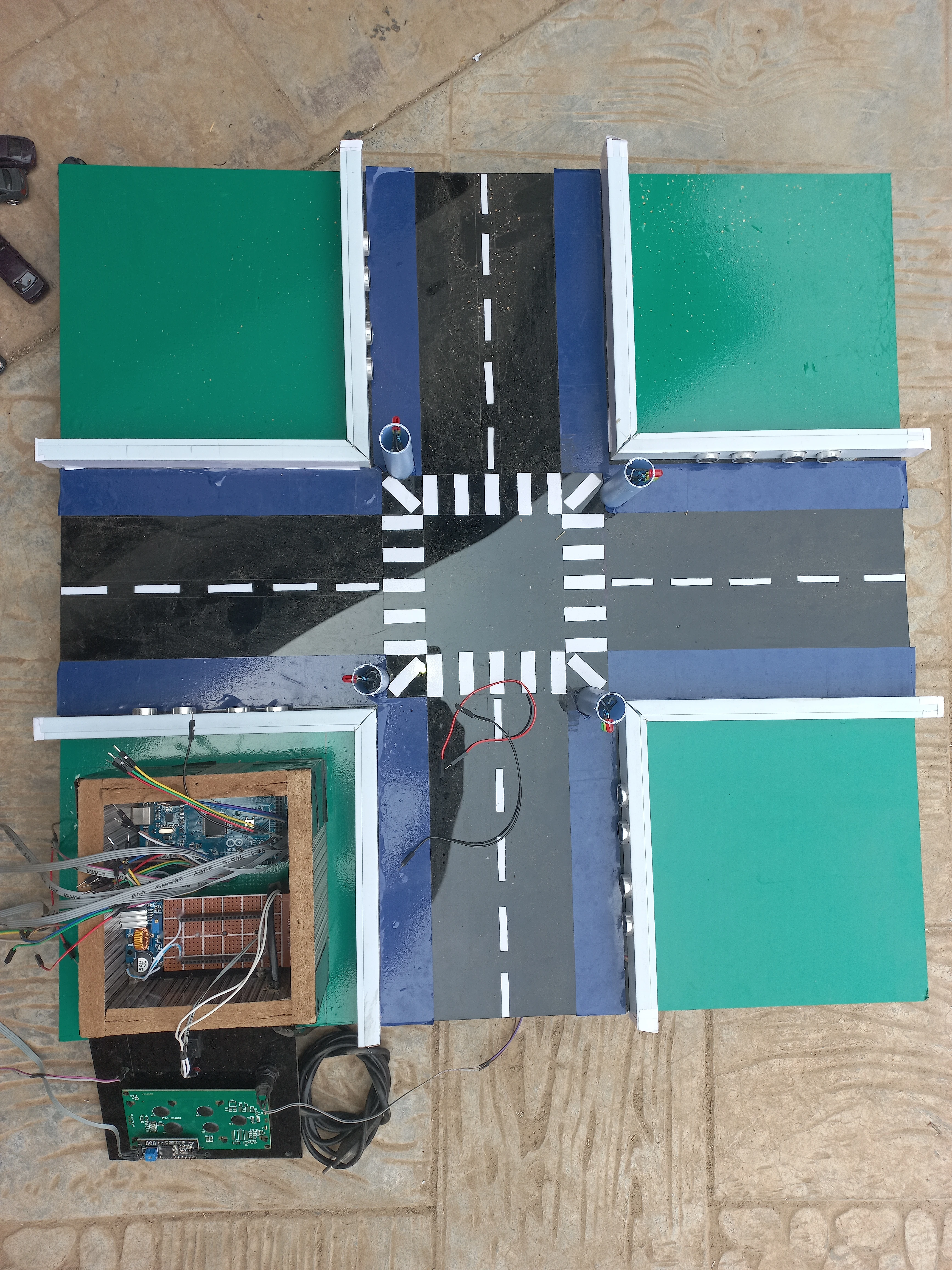
Traditional fixed-cycle traffic lights waste time on empty roads and create unnecessary congestion on busy approaches. This system replaces that rigid pattern with real-time density-based control: two HC-SR04 ultrasonic sensors per lane (front and back) measure vehicle queue length continuously, and each lane is classified as EMPTY, NORMAL, or CROWDED. Green-light duration is then allocated dynamically — 0 s (Smart Interrupt), 15 s (normal), or 30 s (crowded) — so no lane idles unnecessarily while vehicles wait on the opposing axis.
The firmware runs on an Arduino Mega 2560 using a non-blocking millis()-based 6-state machine. This architecture allows the microcontroller to simultaneously scan all eight sensors every 300 ms, update the 20×4 I2C LCD countdown display every 250 ms, manage yellow-phase transitions, and respond instantly to the hardware emergency override button — all without a single delay() call in the main loop.
delay() callsThe system is organised as a single non-blocking loop() that services five concurrent tasks:
| Component | Model / Spec | Role |
|---|---|---|
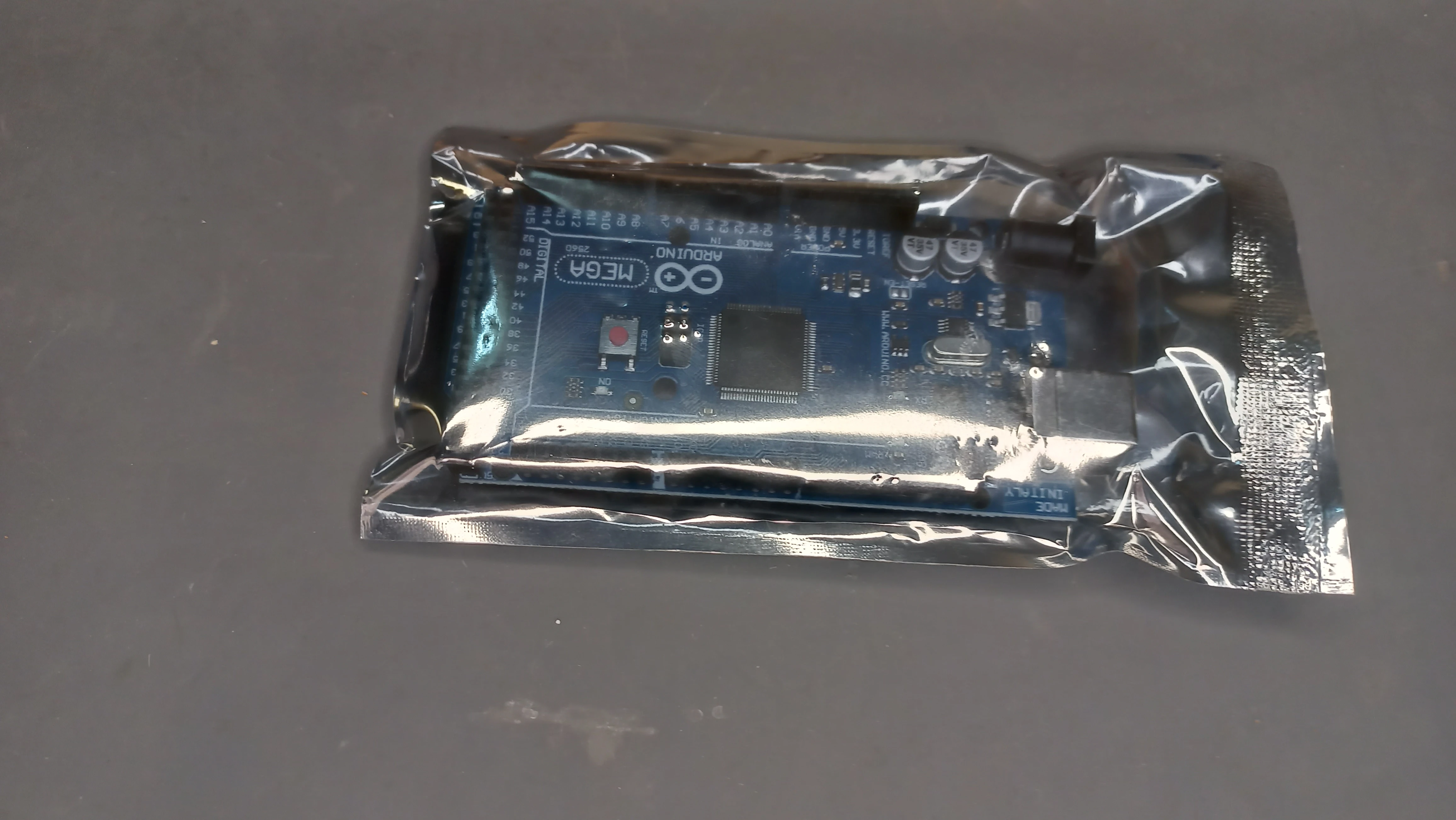
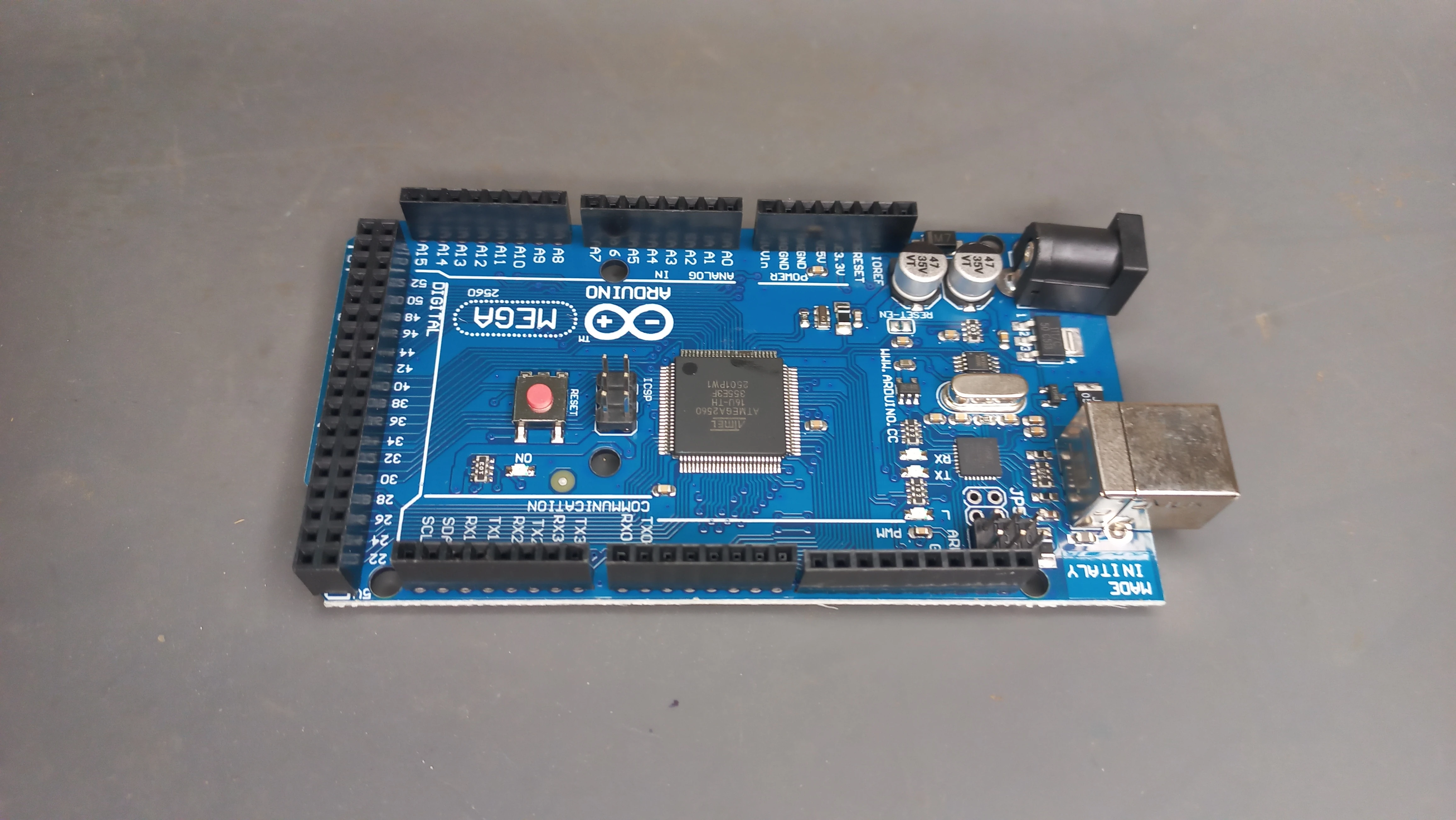
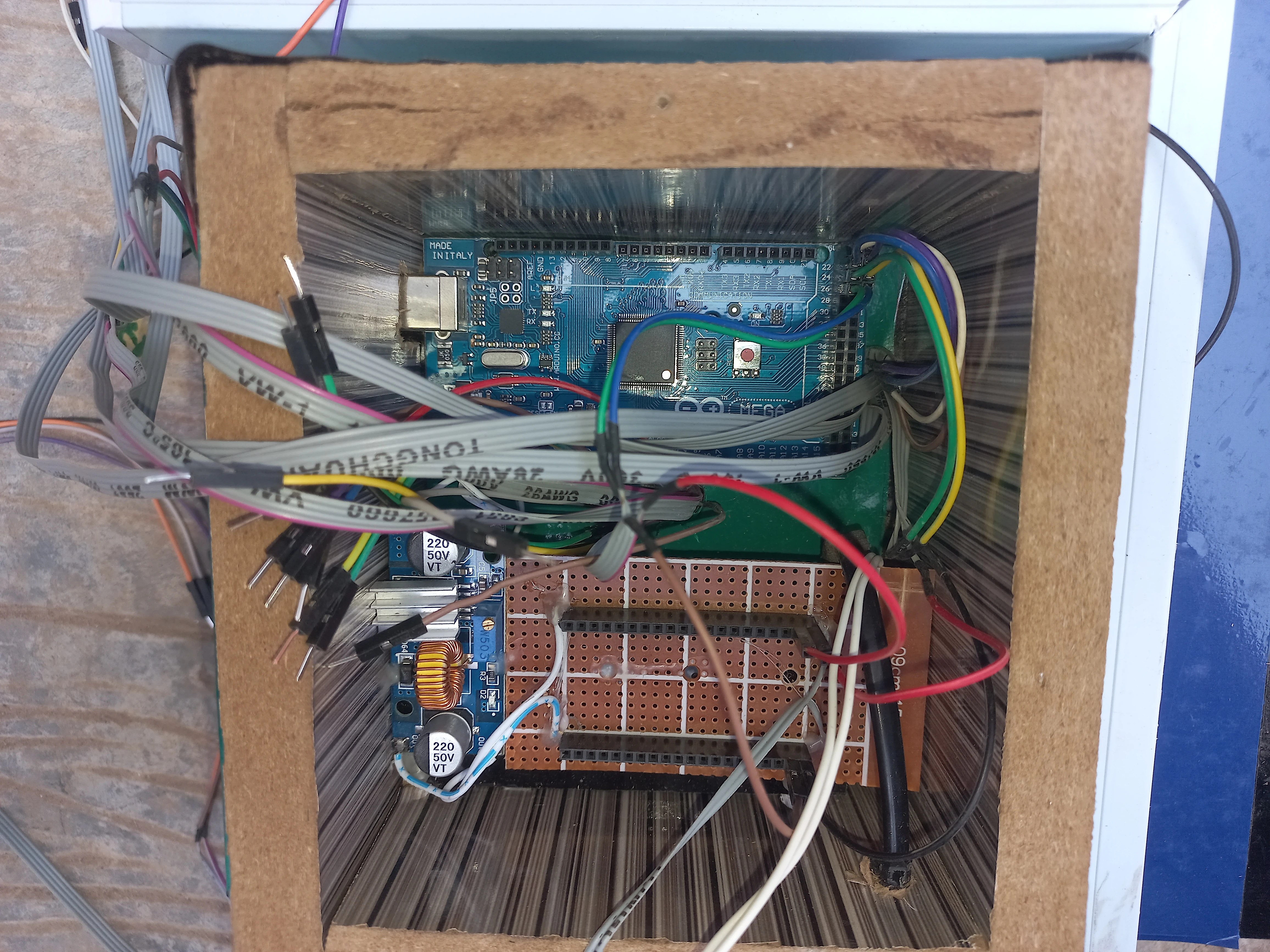
| Microcontroller | Arduino Mega 2560 | Central processing, GPIO control, I2C LCD, serial debug |
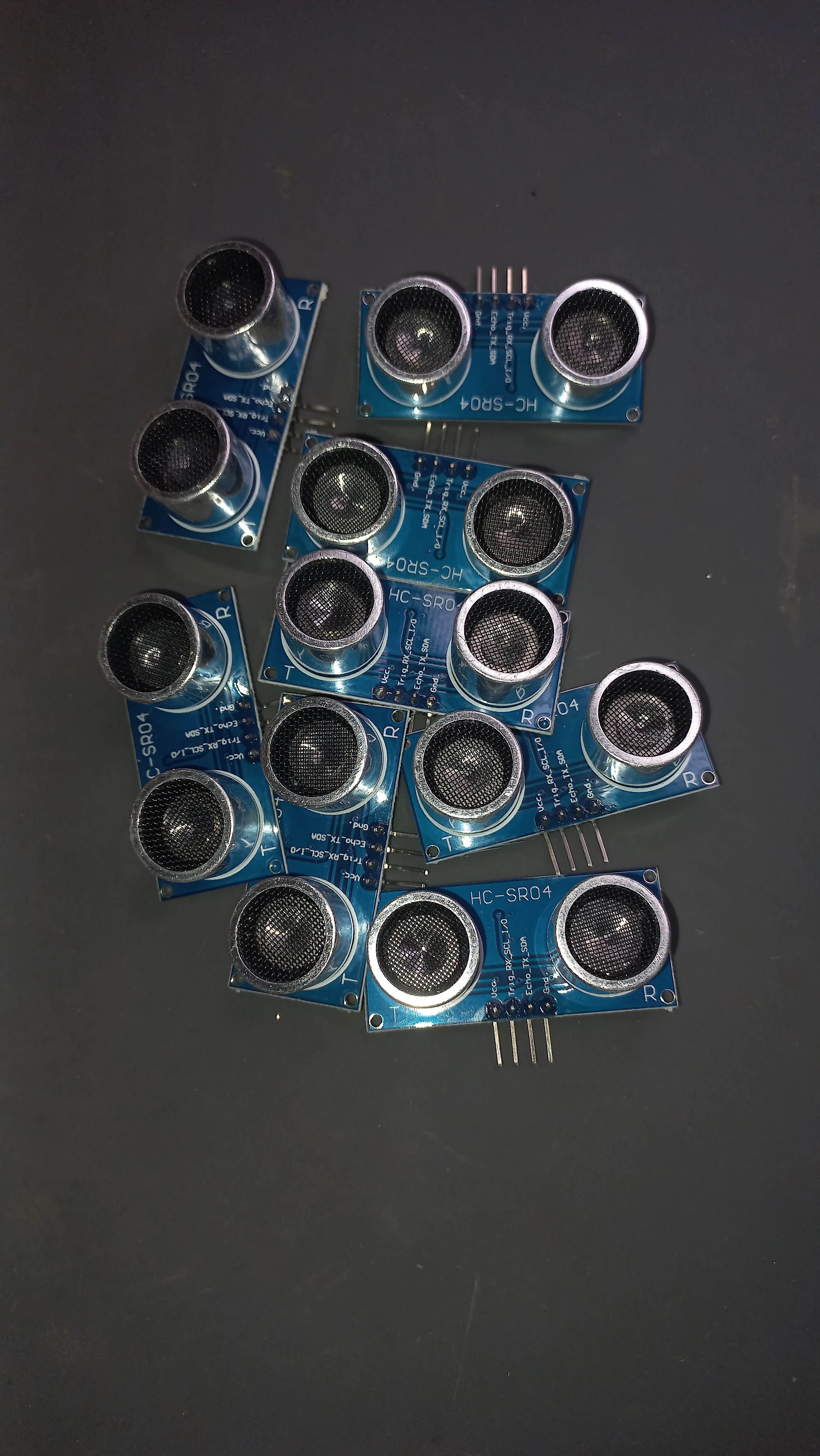
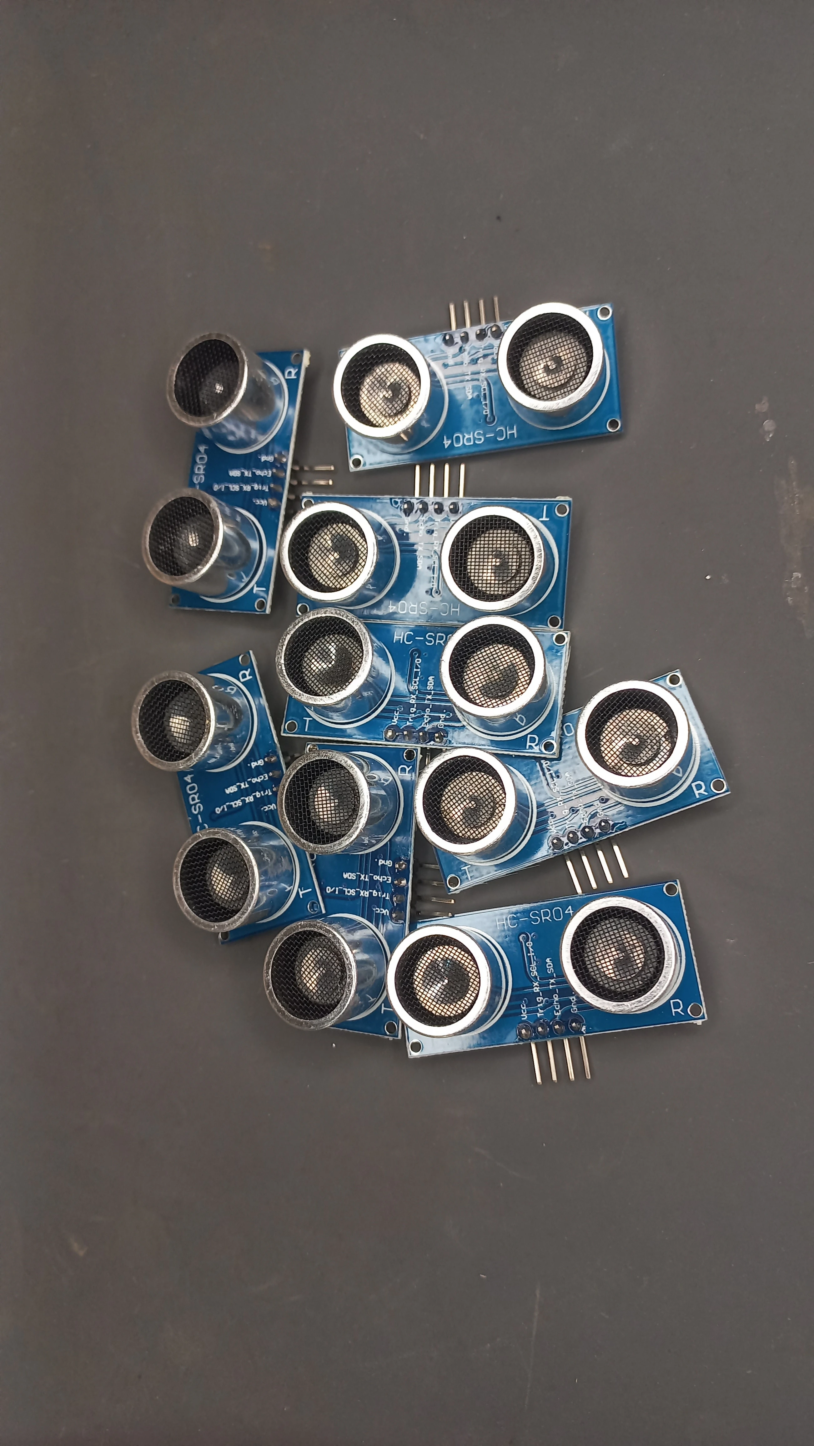
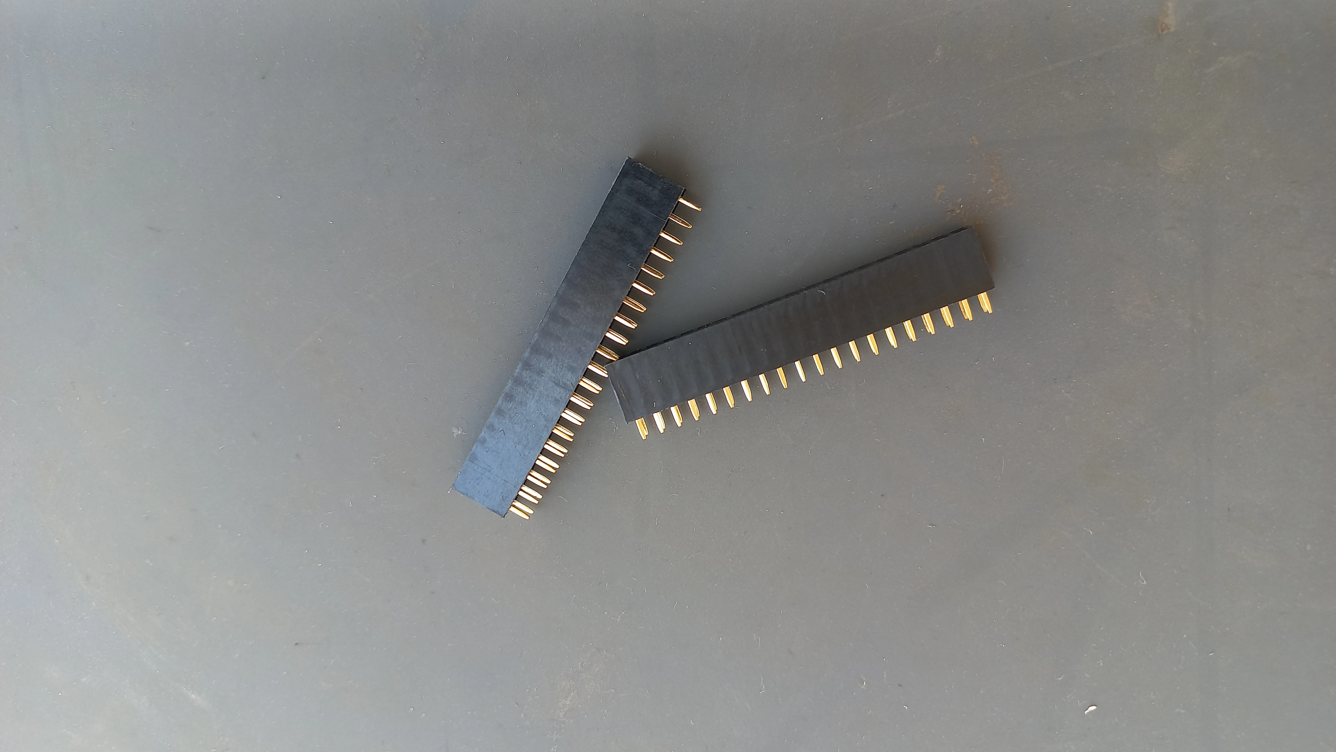
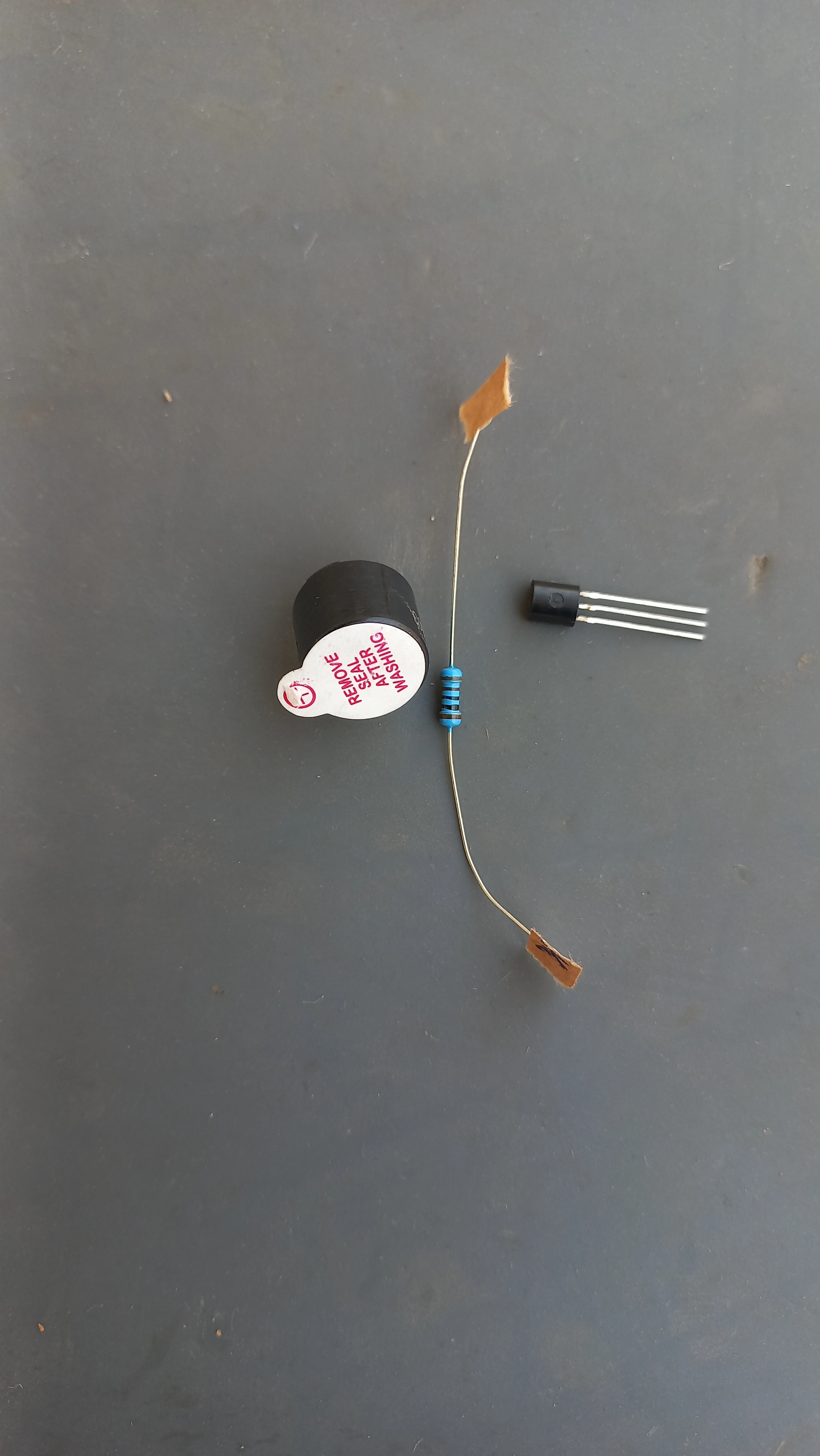
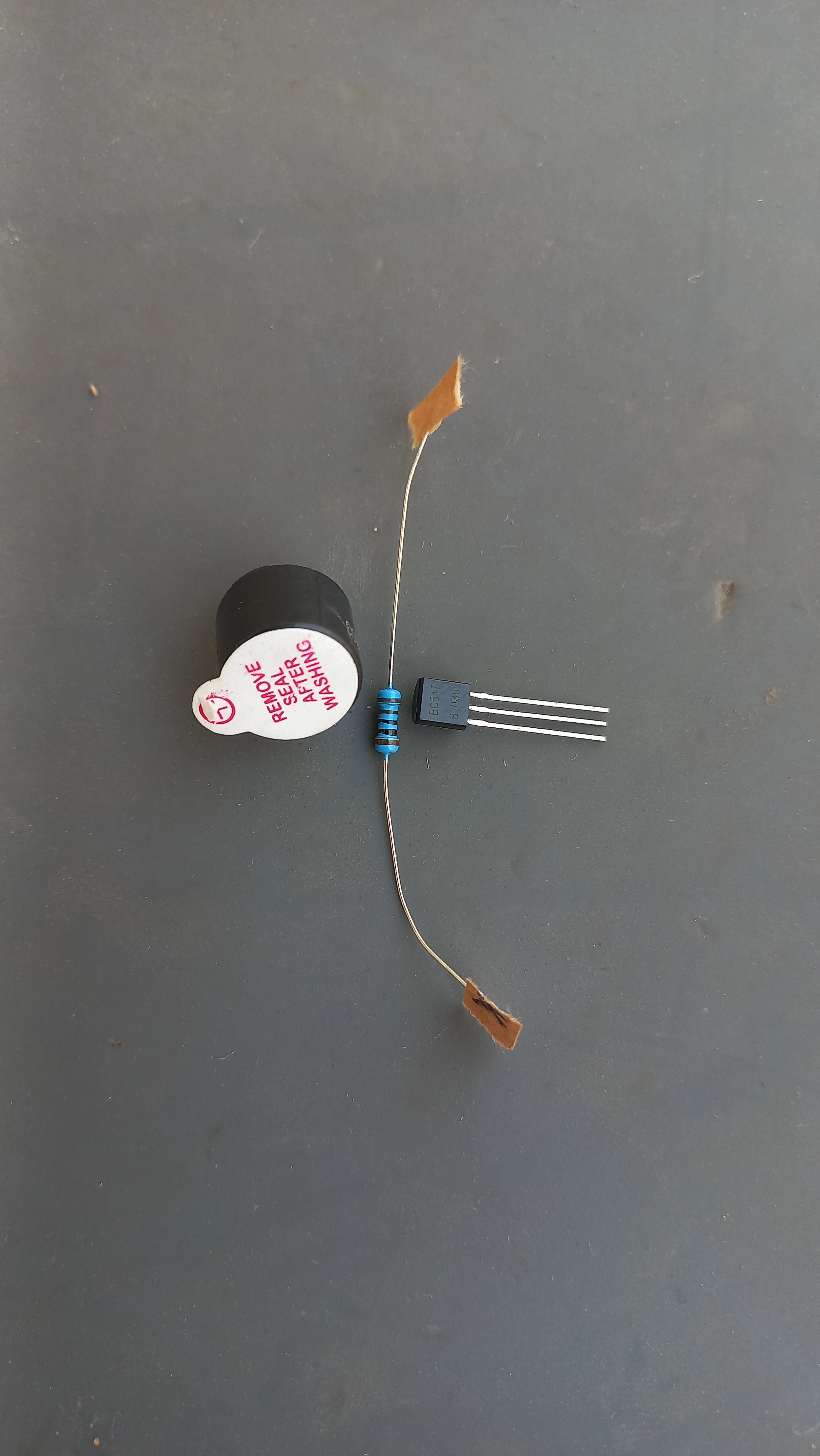
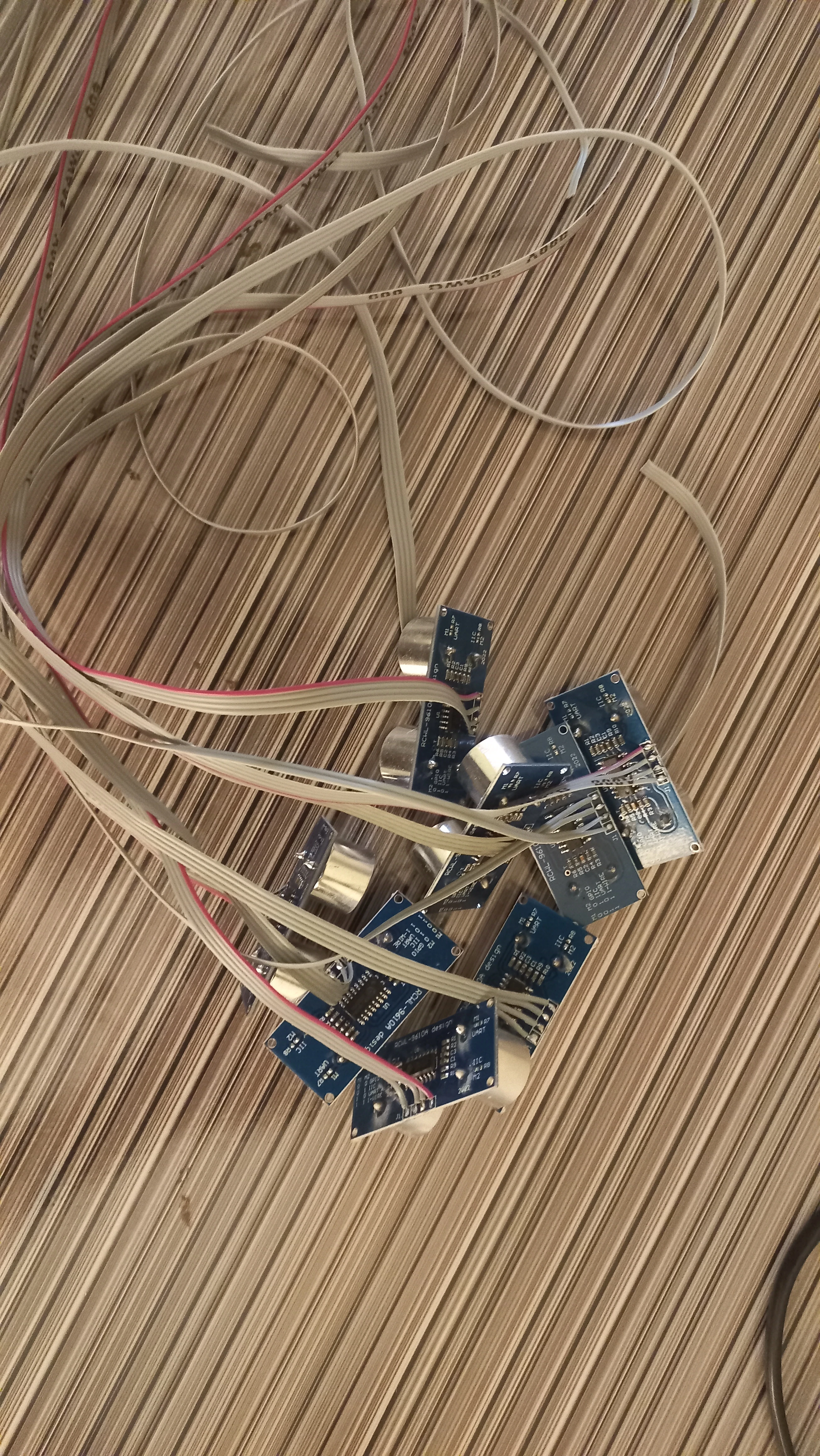
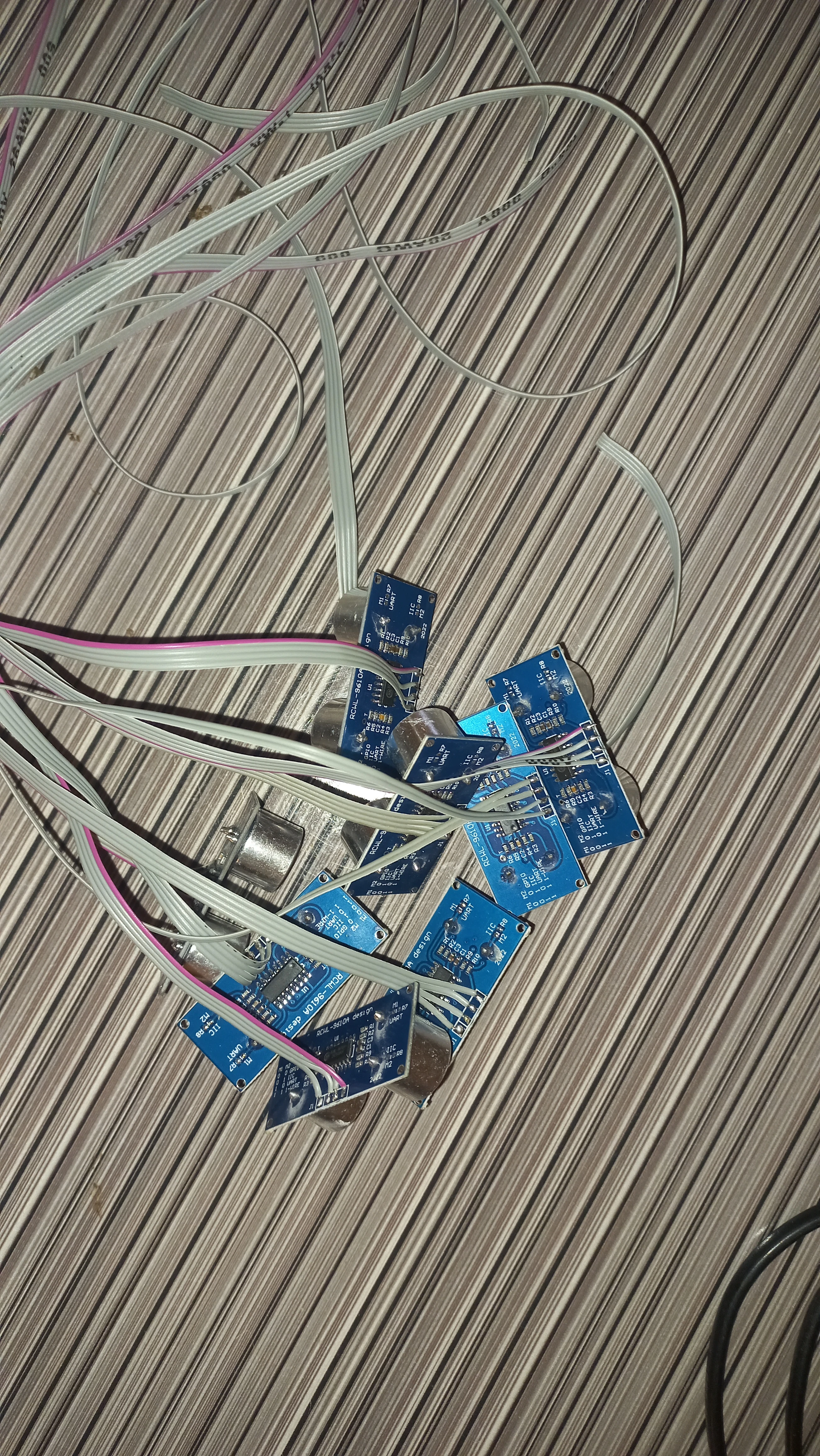
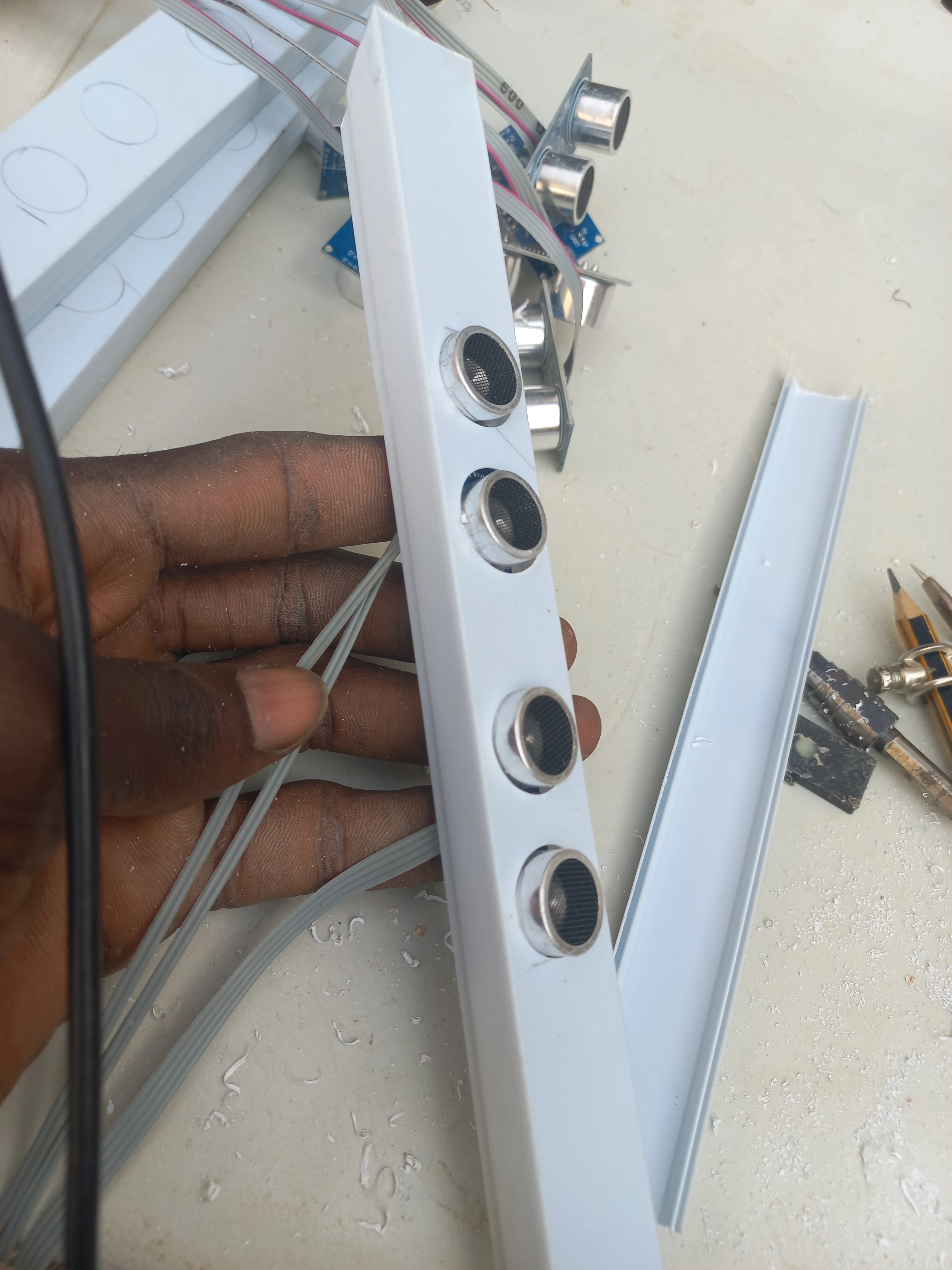
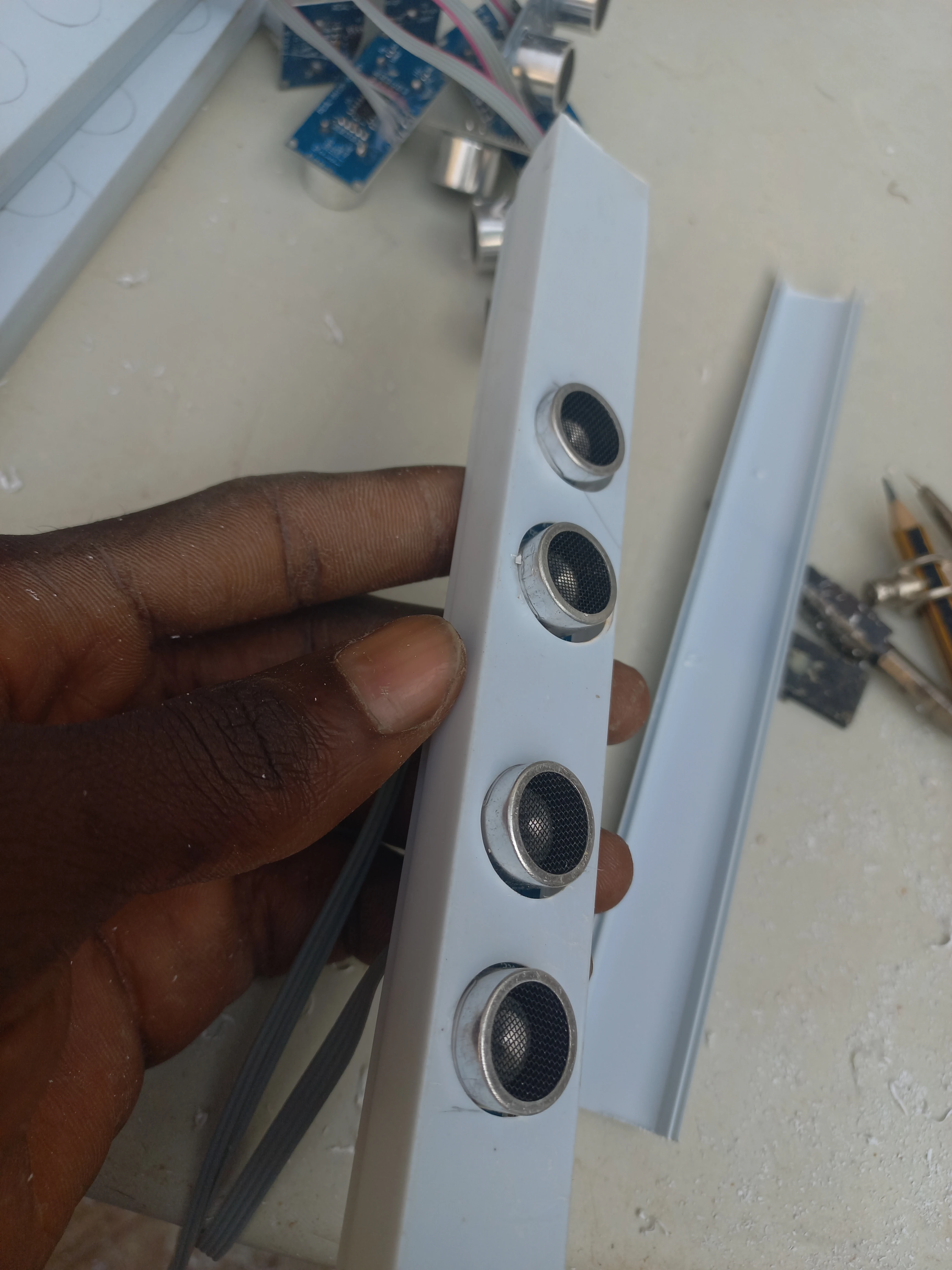
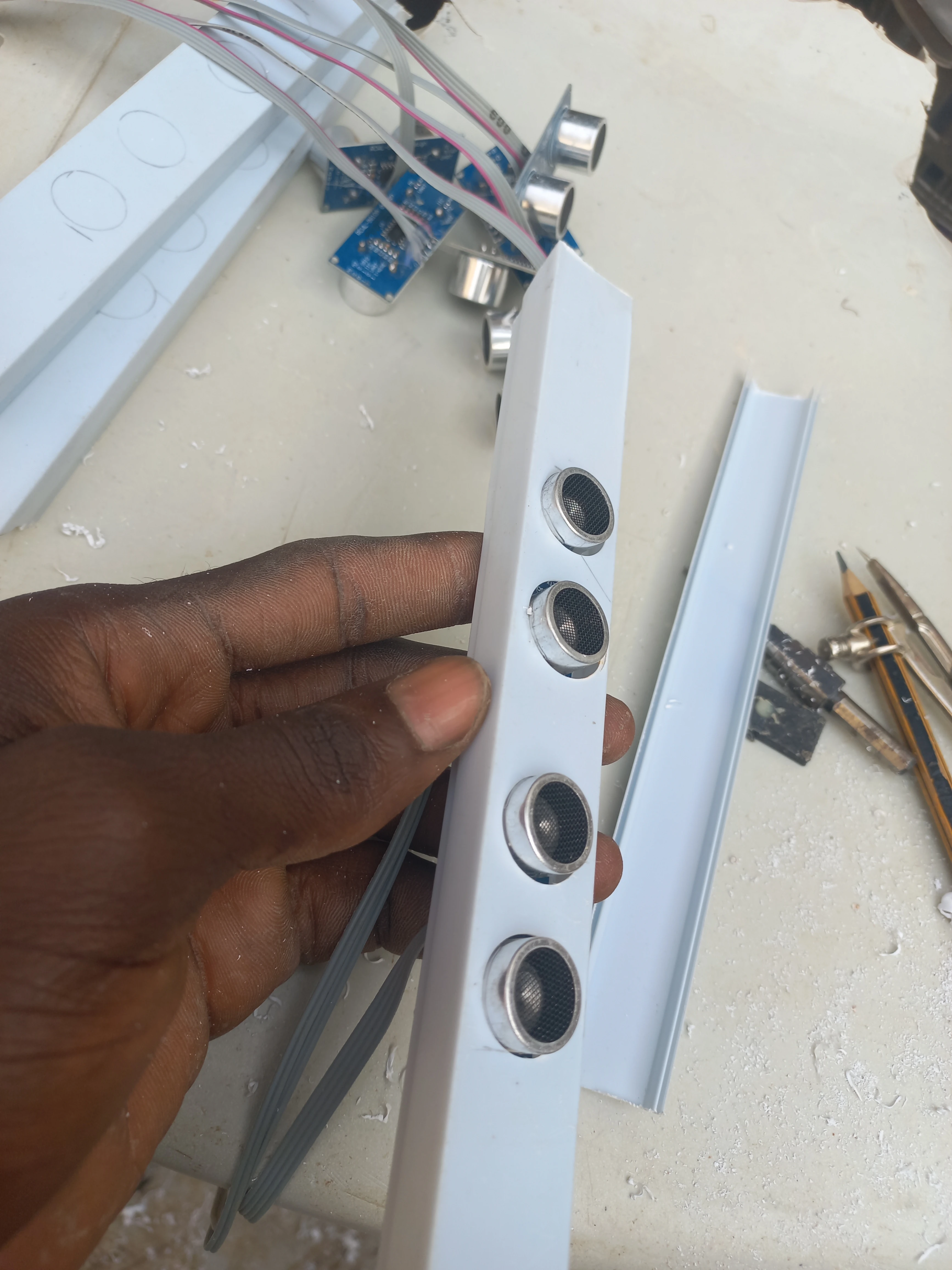
| Distance Sensors | HC-SR04 Ultrasonic ×8 | Front and back vehicle detection per lane; Trig/Echo digital pairs |
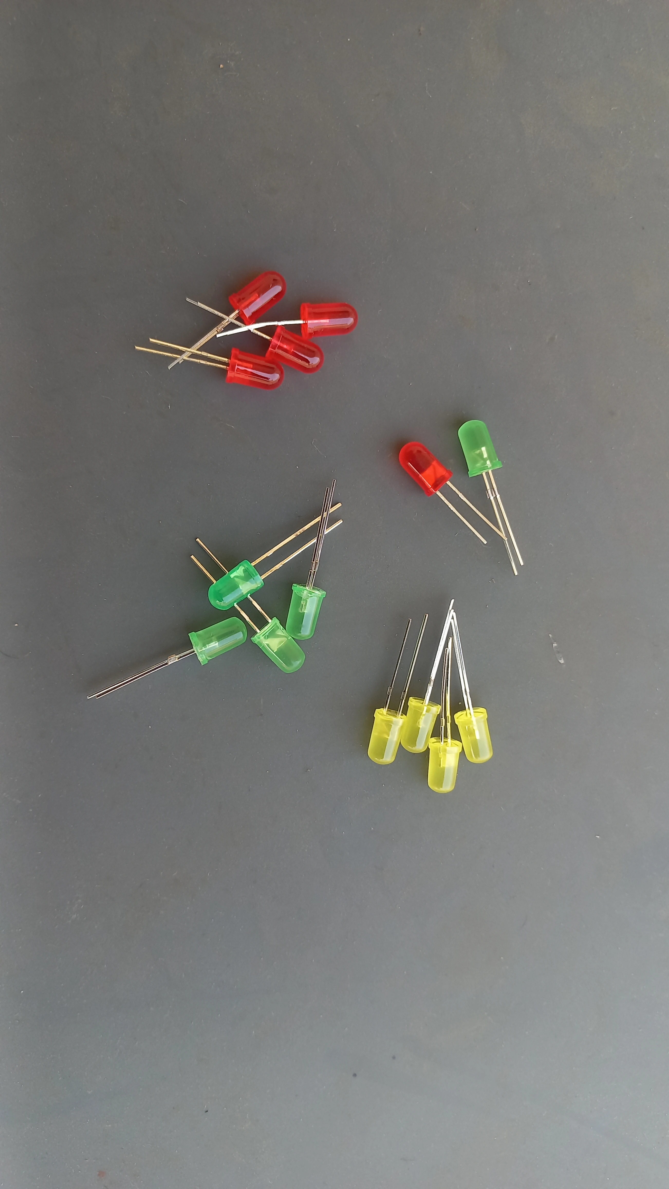
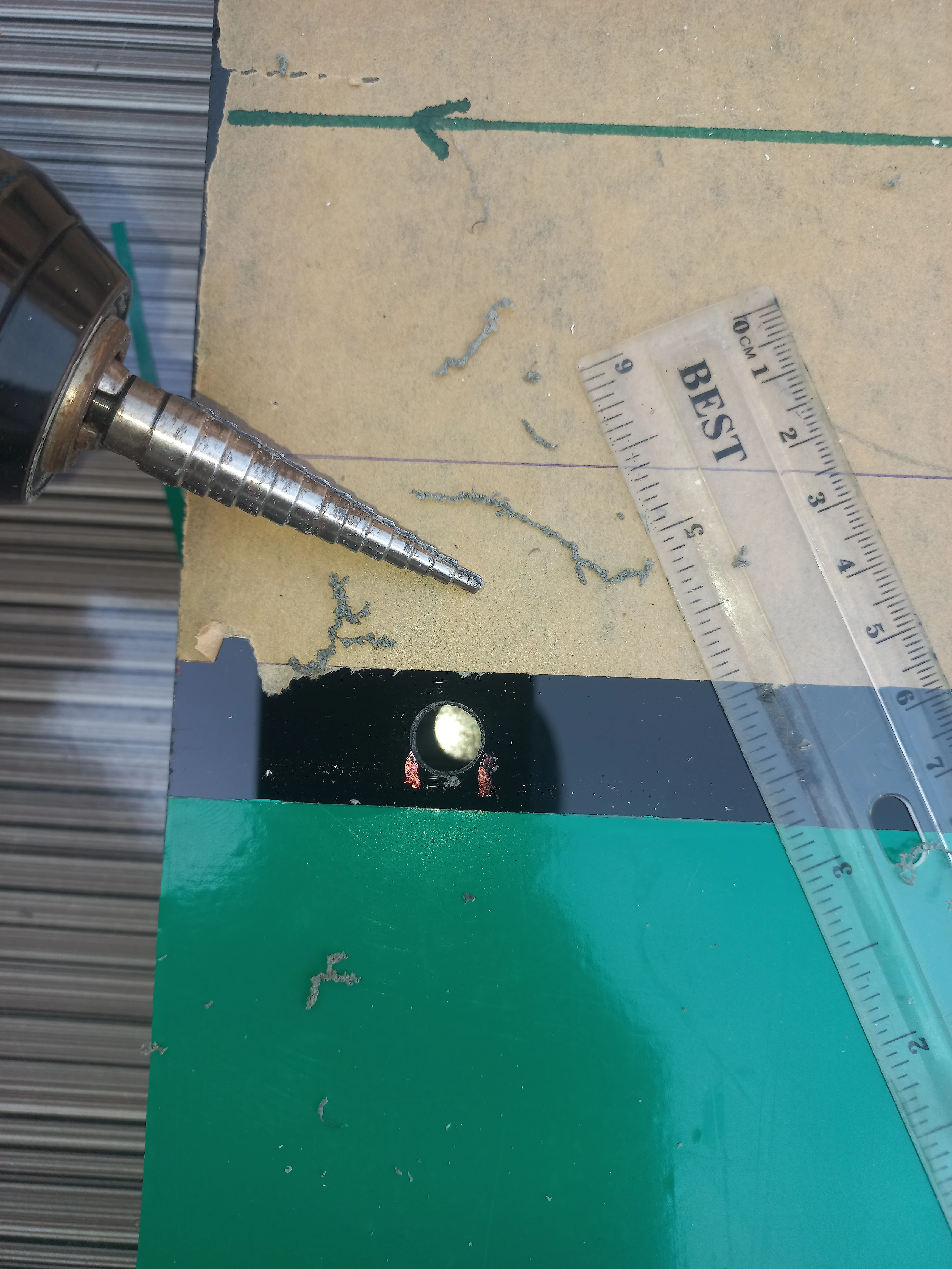
| Traffic LEDs | 5 mm LEDs: Red, Yellow, Green ×4 lanes (12 total) | Traffic signal output for each lane stop-line |
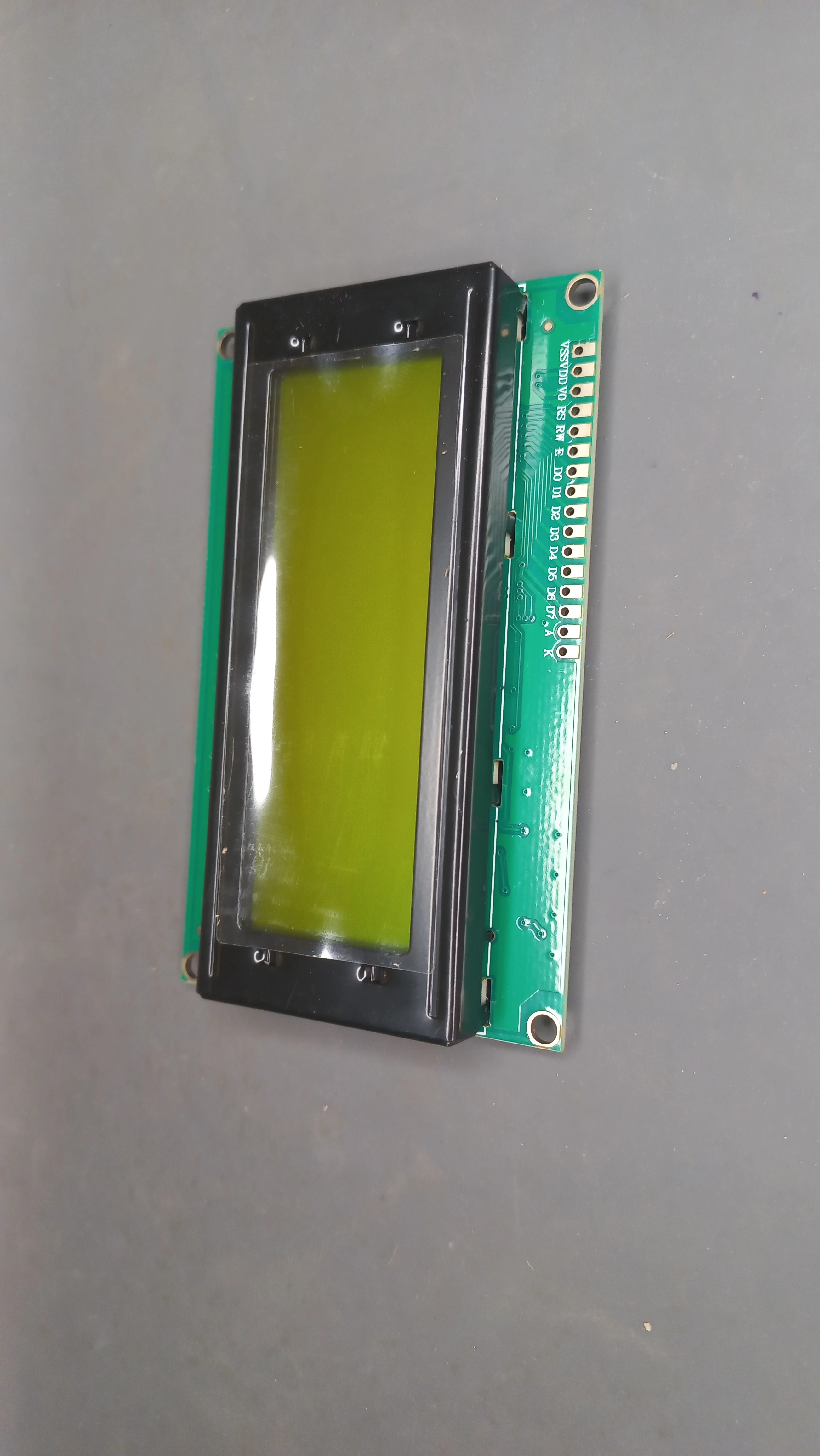
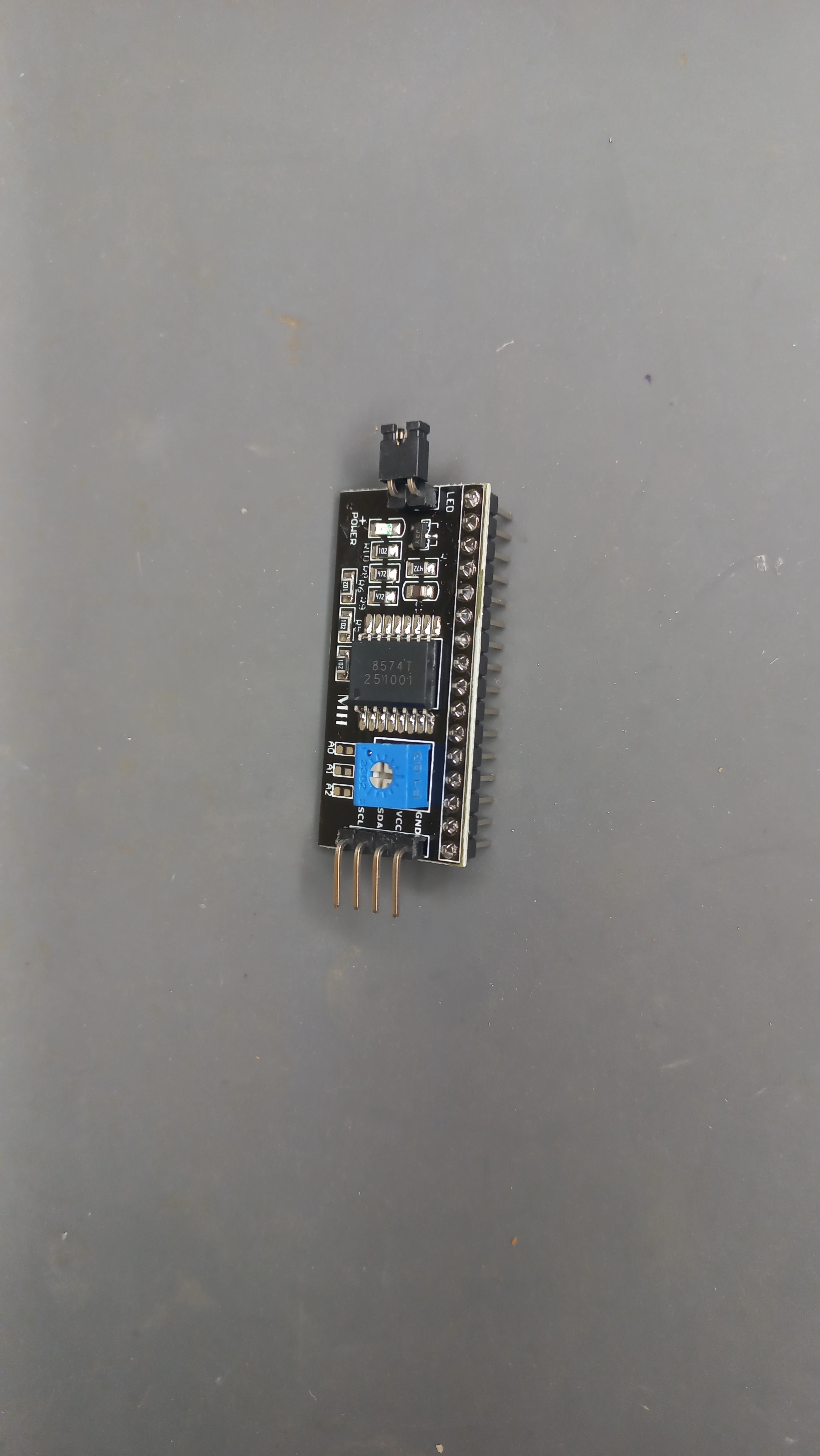
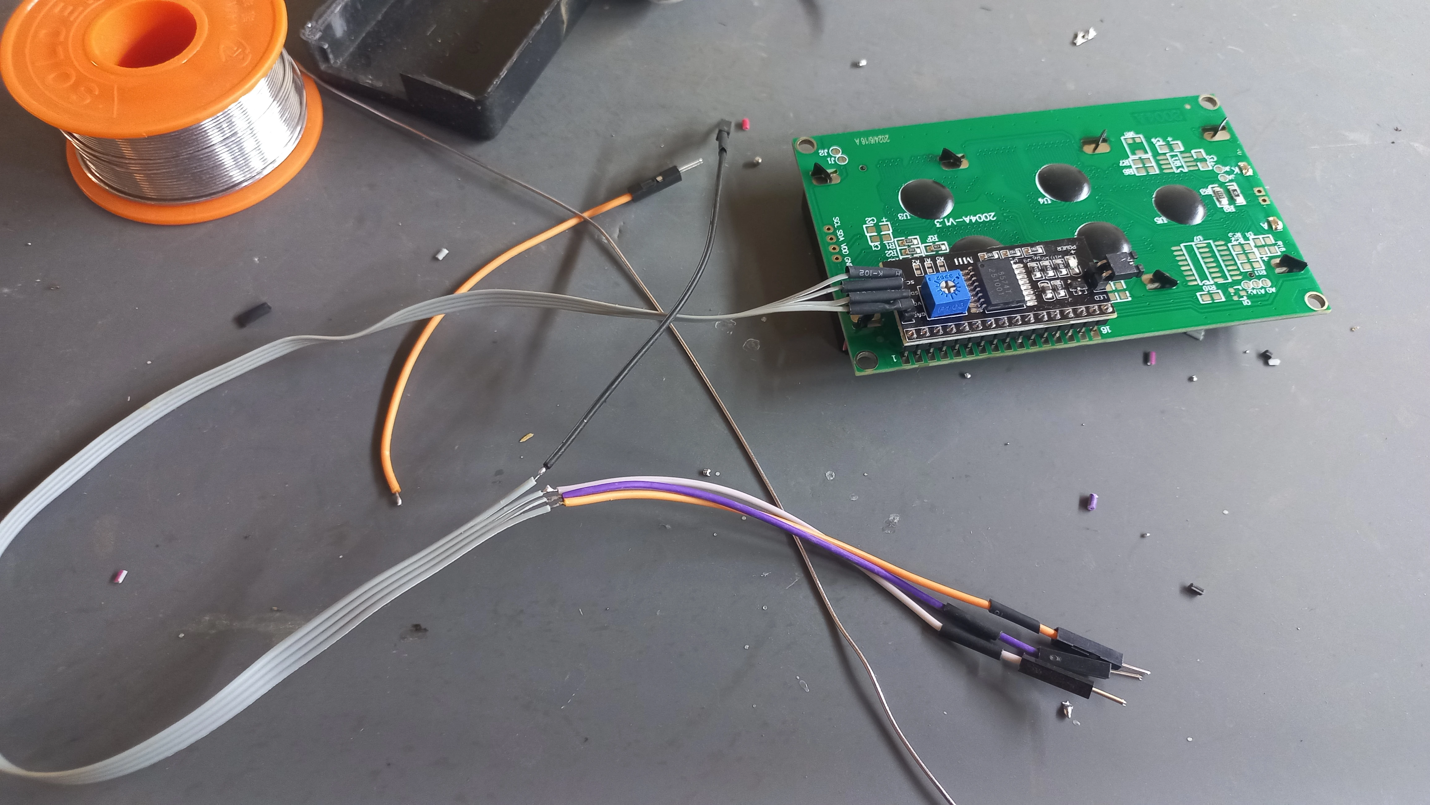
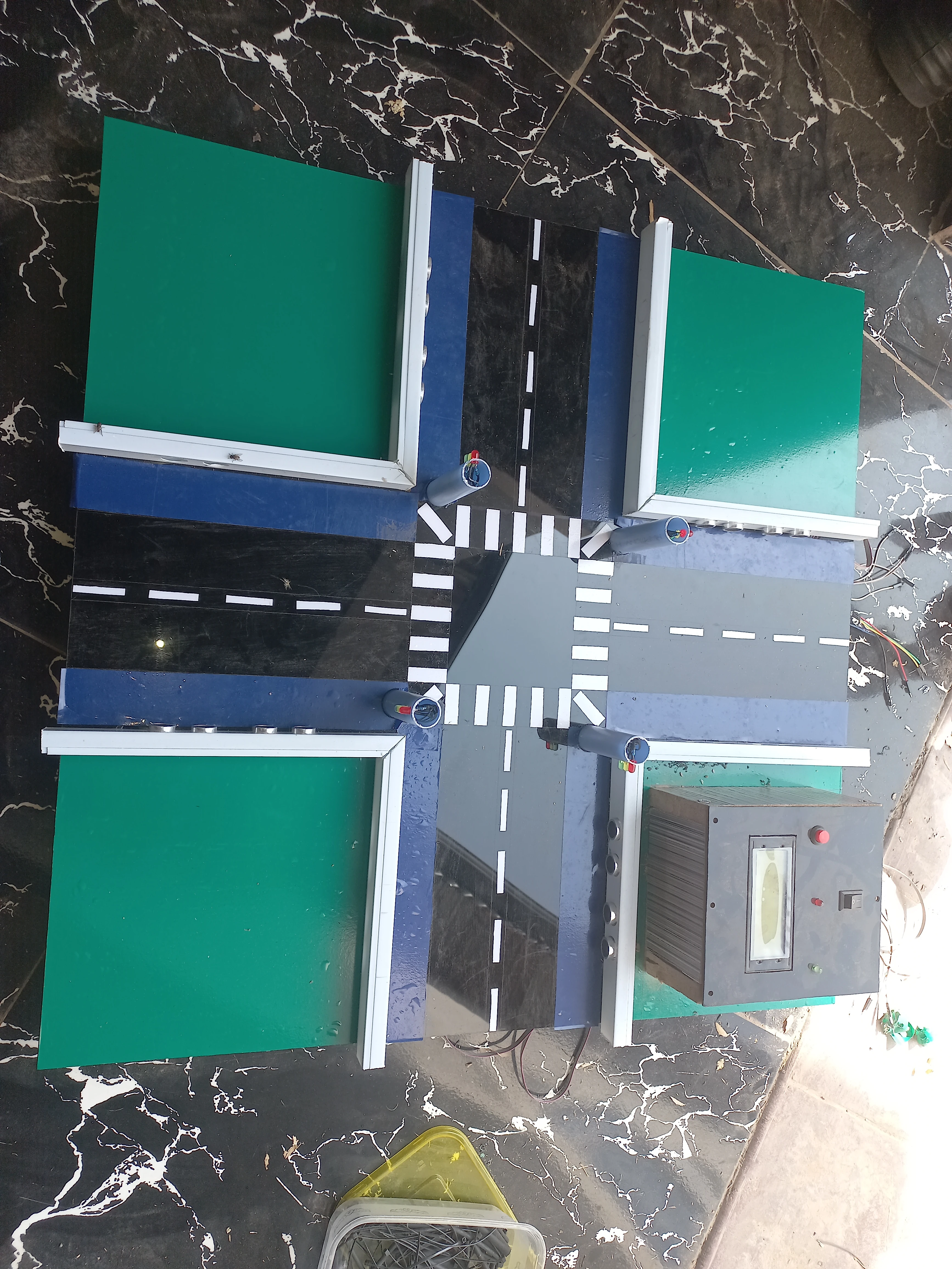
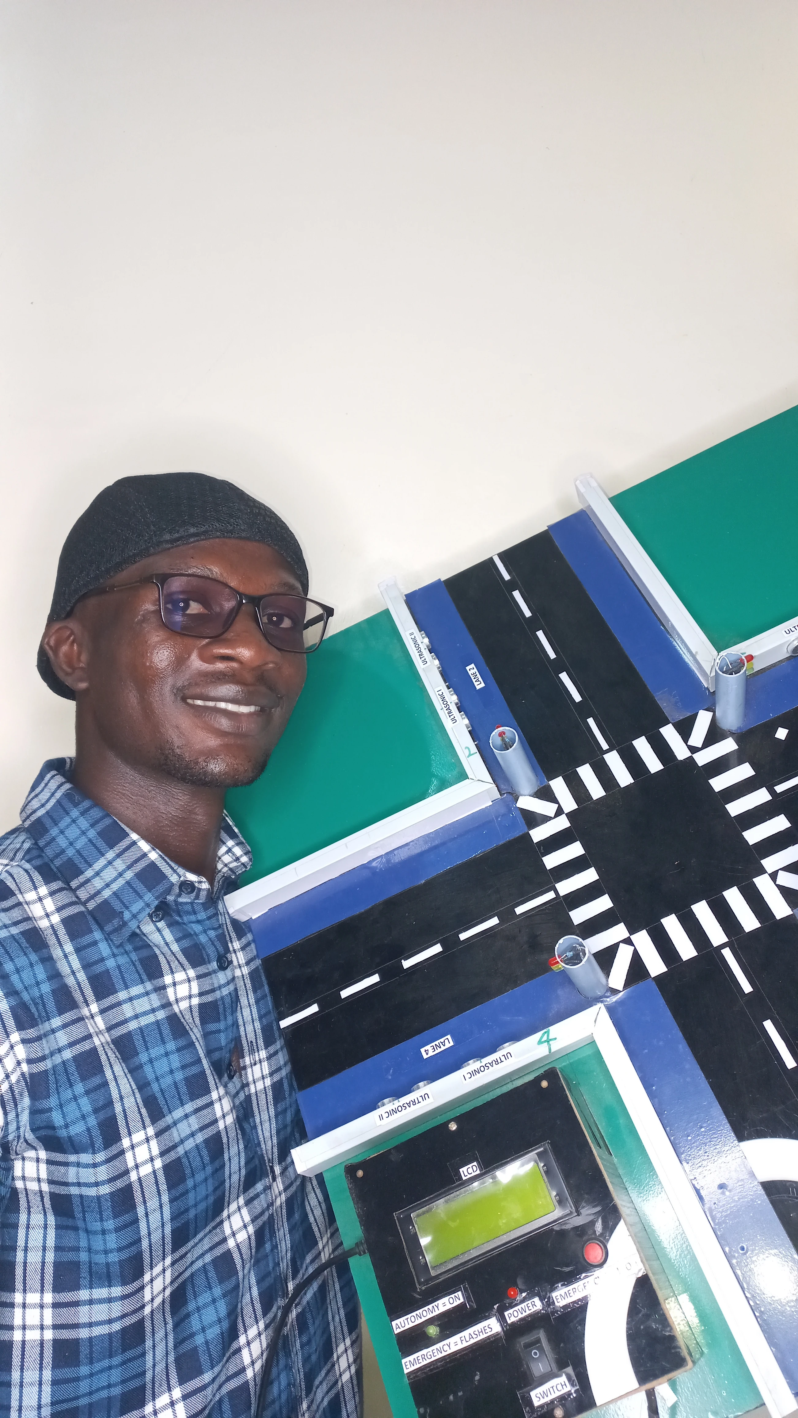
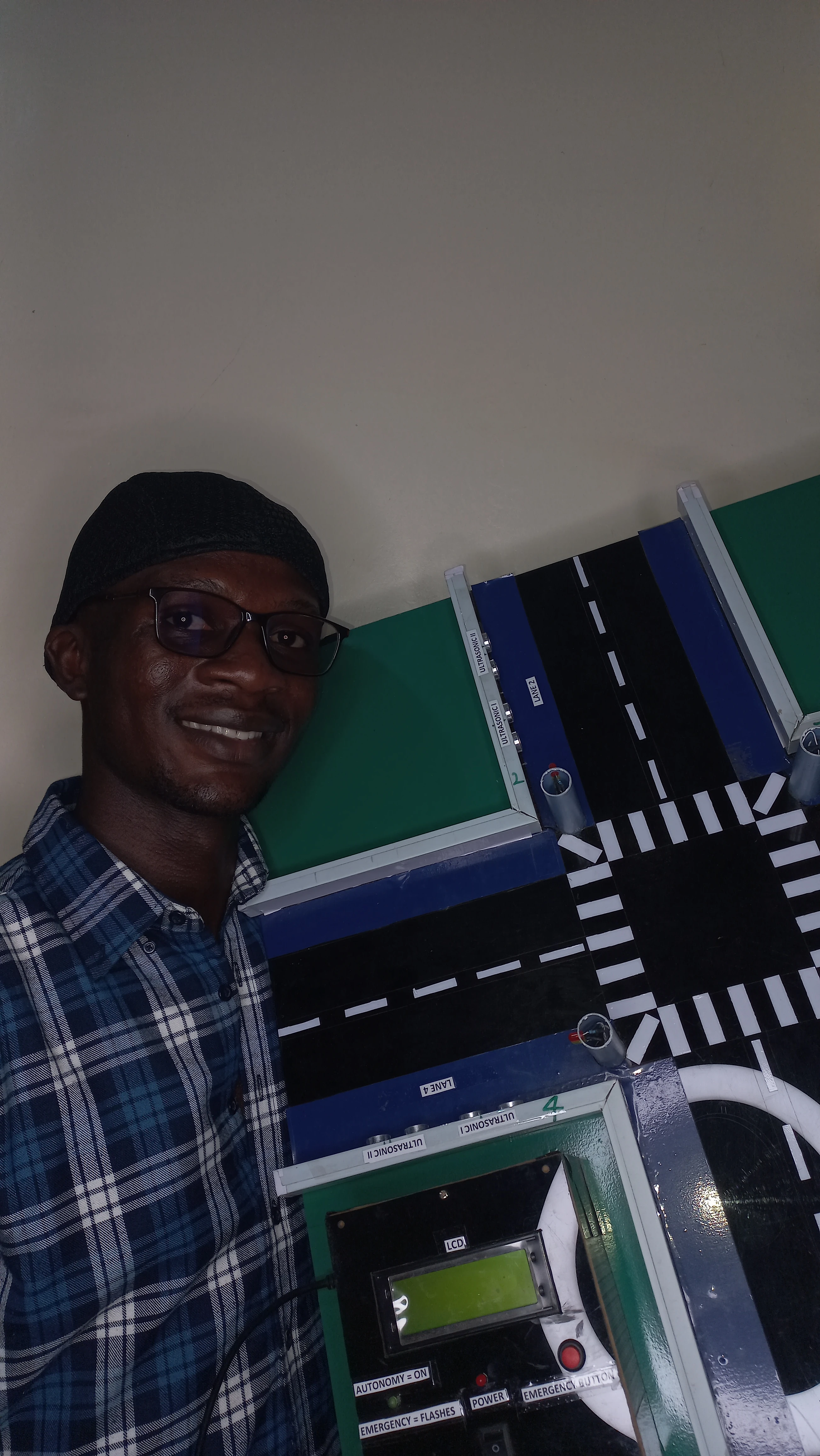
| LCD Display | 20×4 I2C LCD (PCF8574 backpack, address 0x27) | Live dashboard: active axis, density, phase mode, countdown |
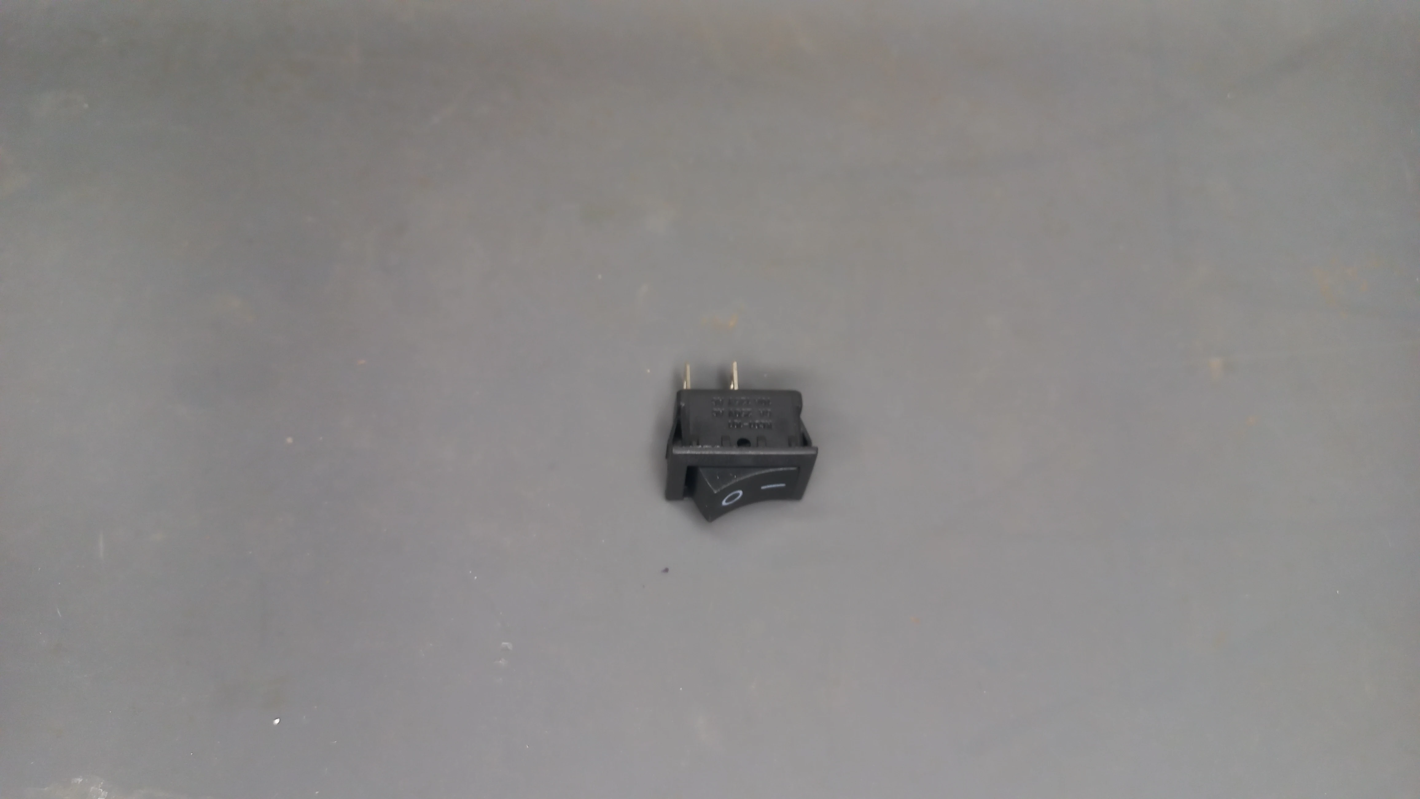
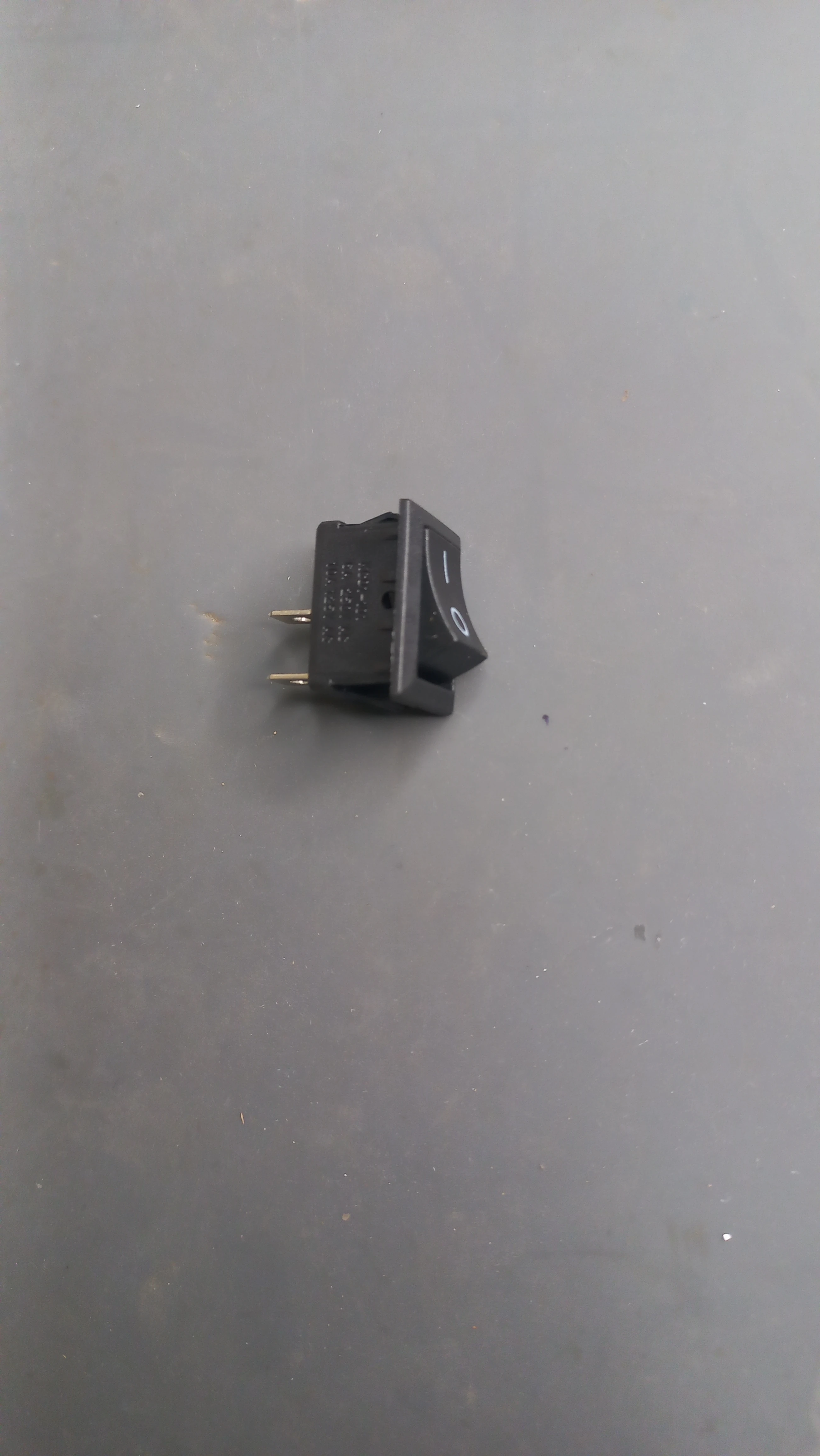
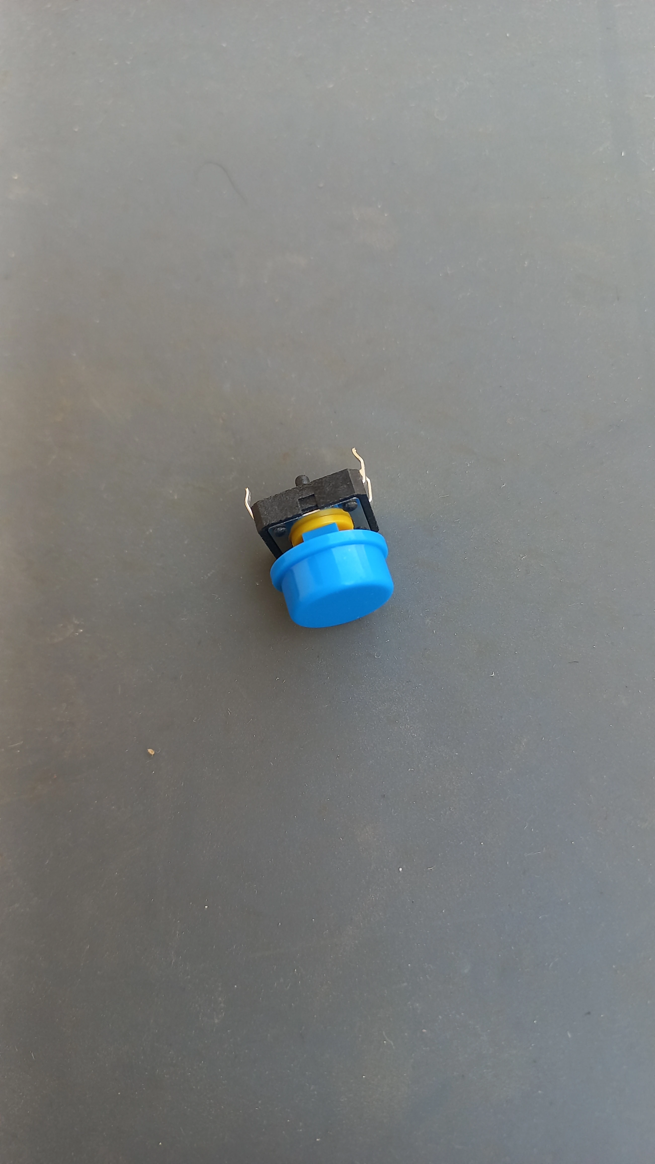
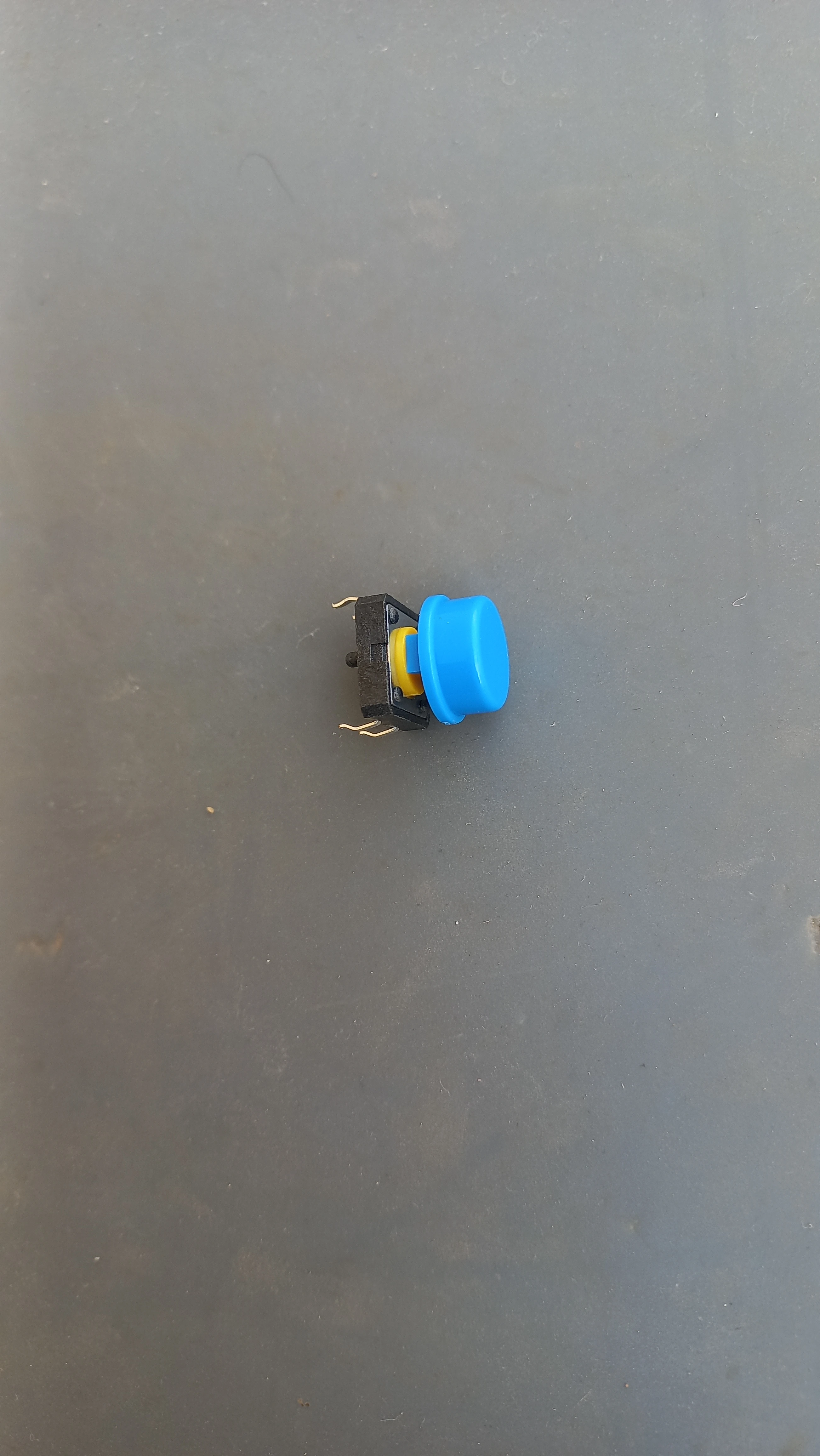
| Emergency Button | Tactile push button (Pin 12, INPUT_PULLUP) | Hardware override toggle; sets all lanes RED |
| Console LED | LED on Pin 13 | Solid = normal auto mode; 200 ms flash = emergency mode |
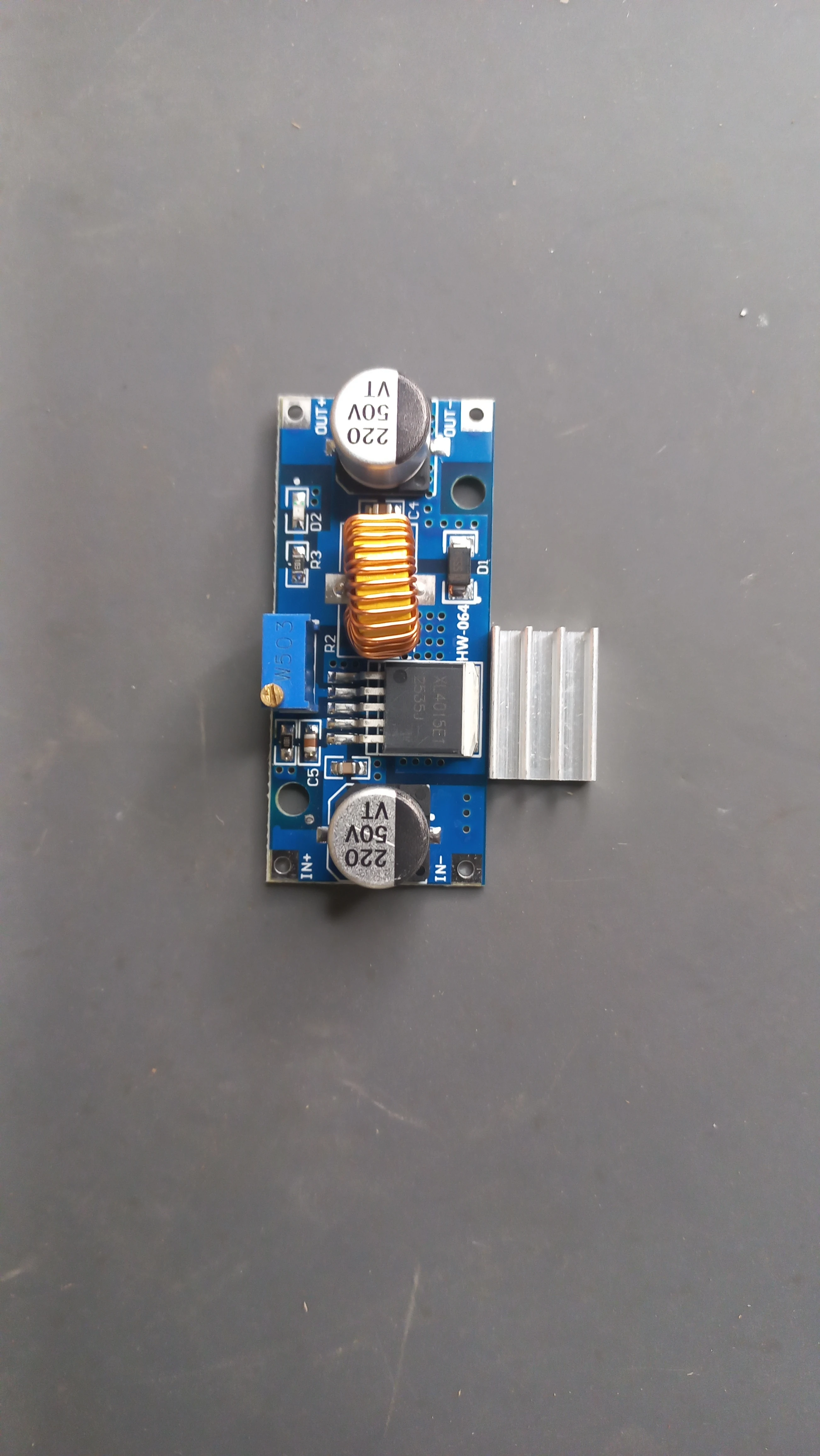
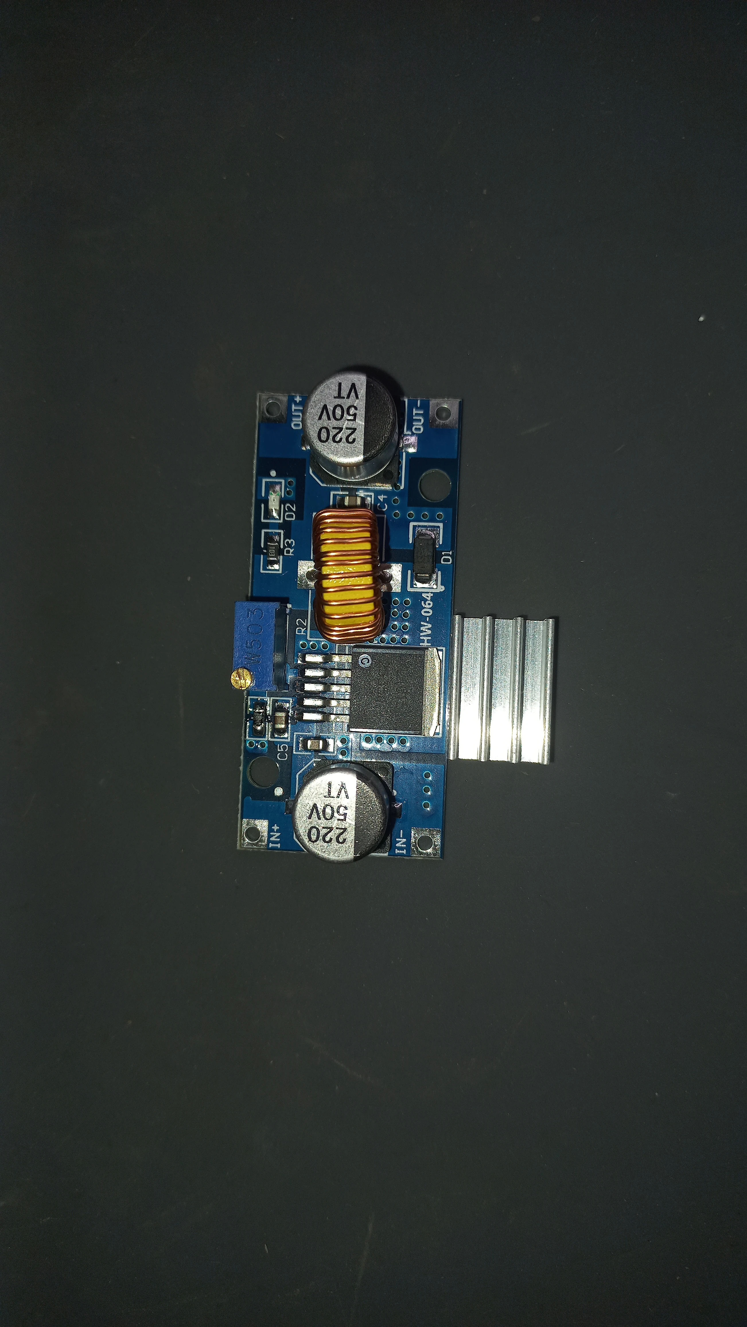
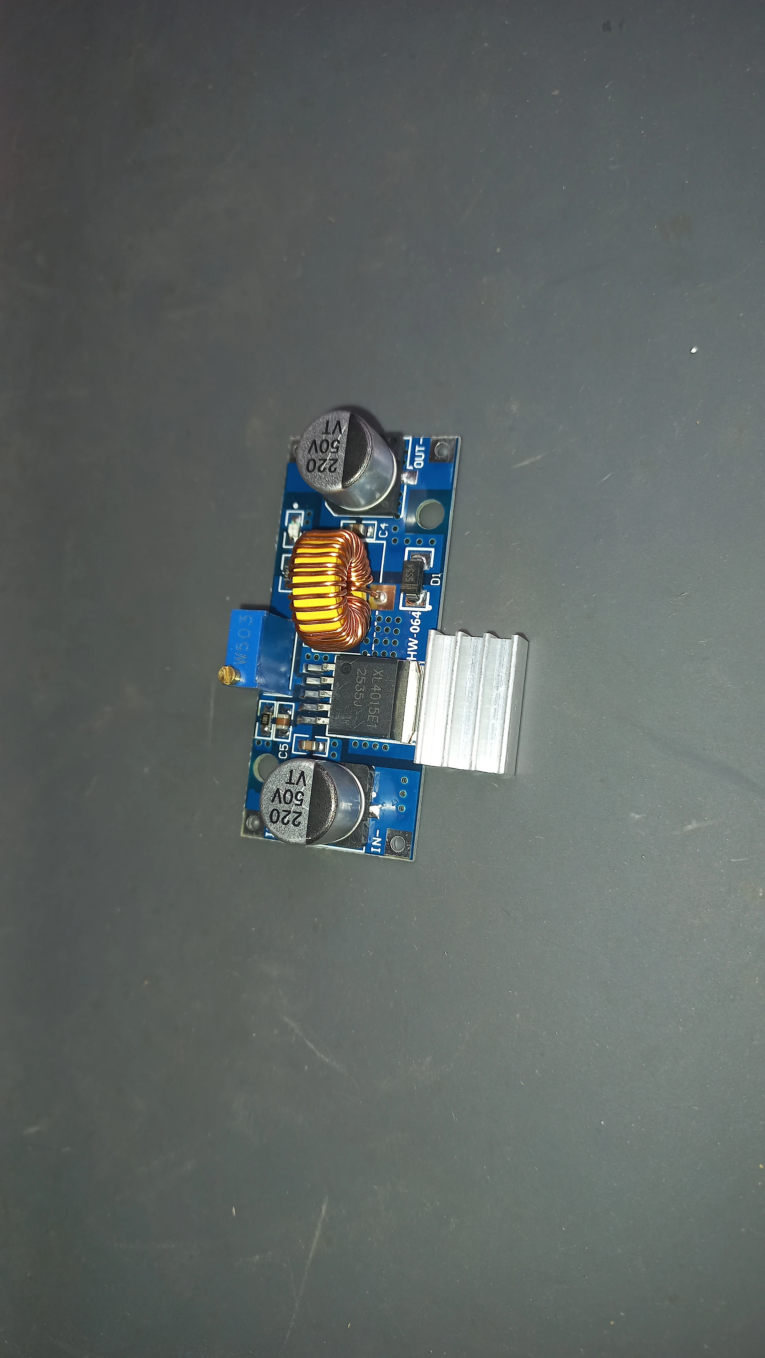
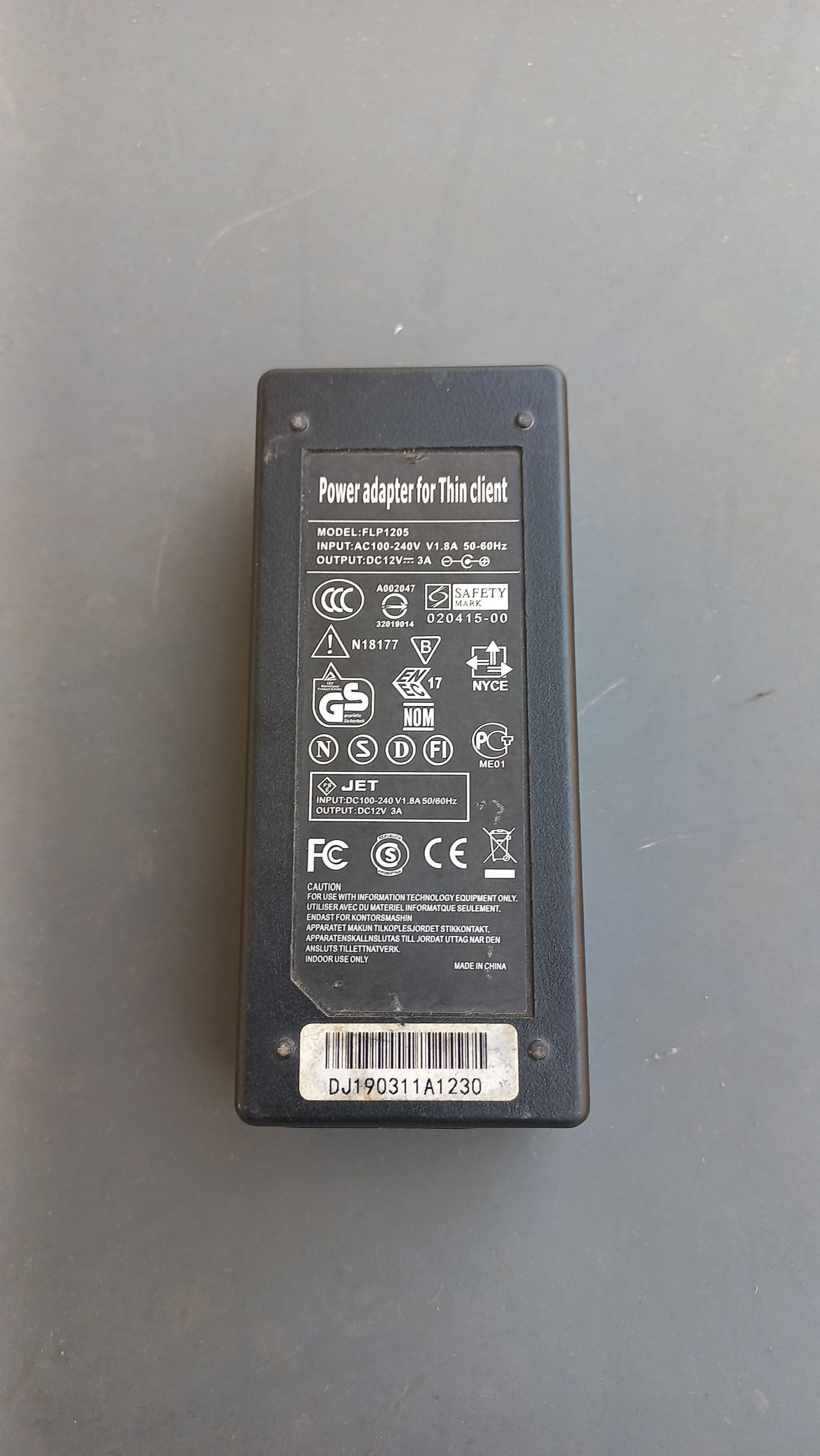
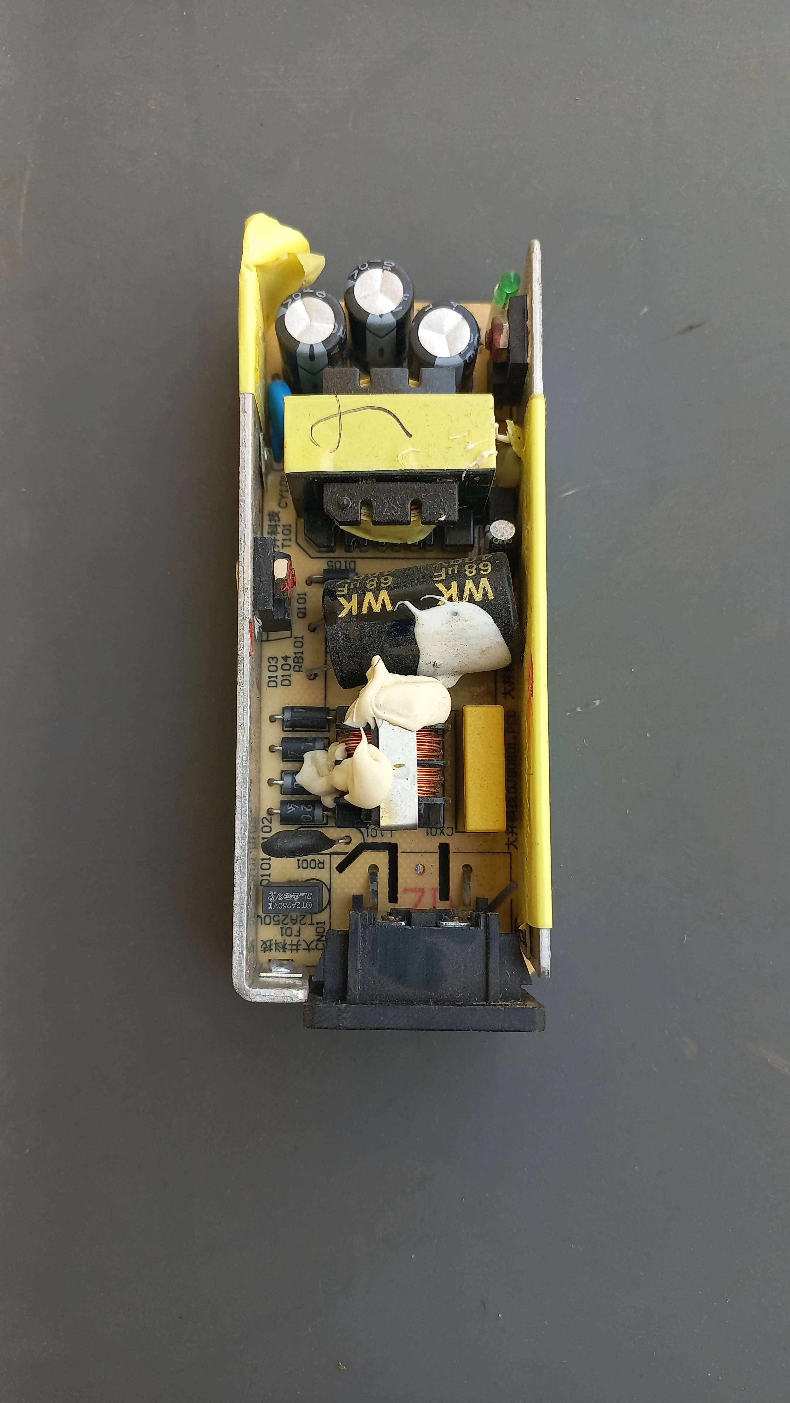
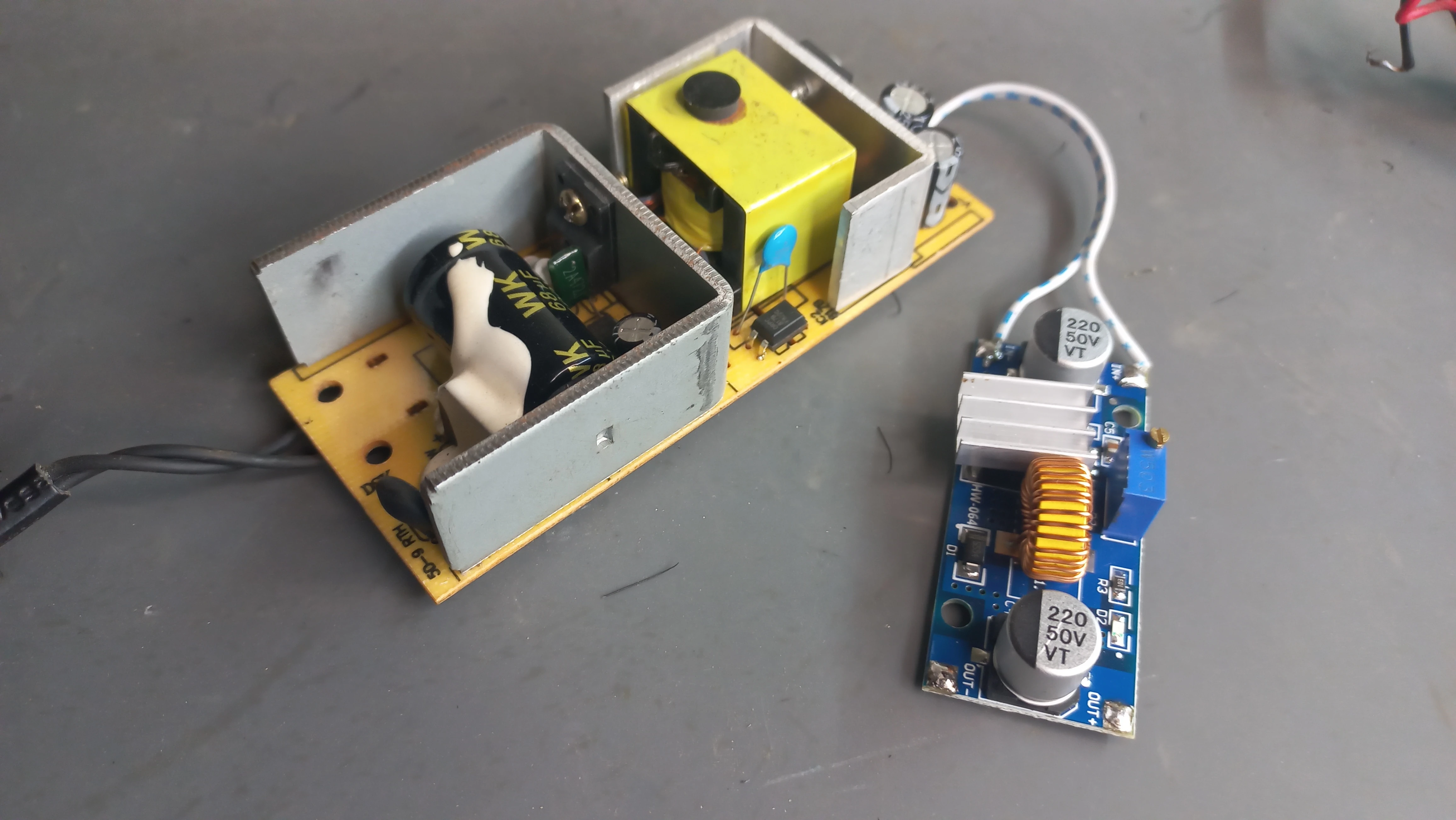
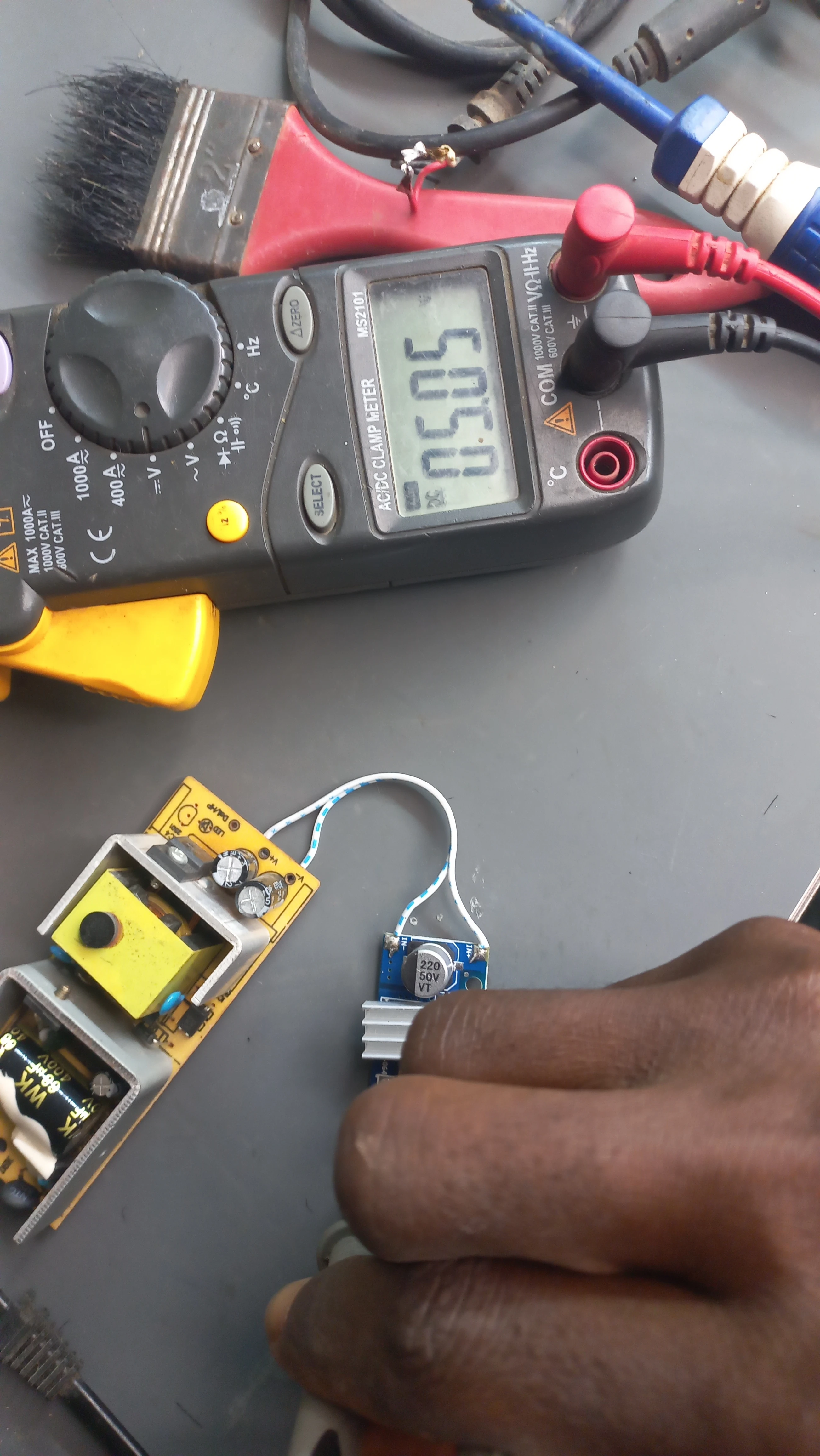
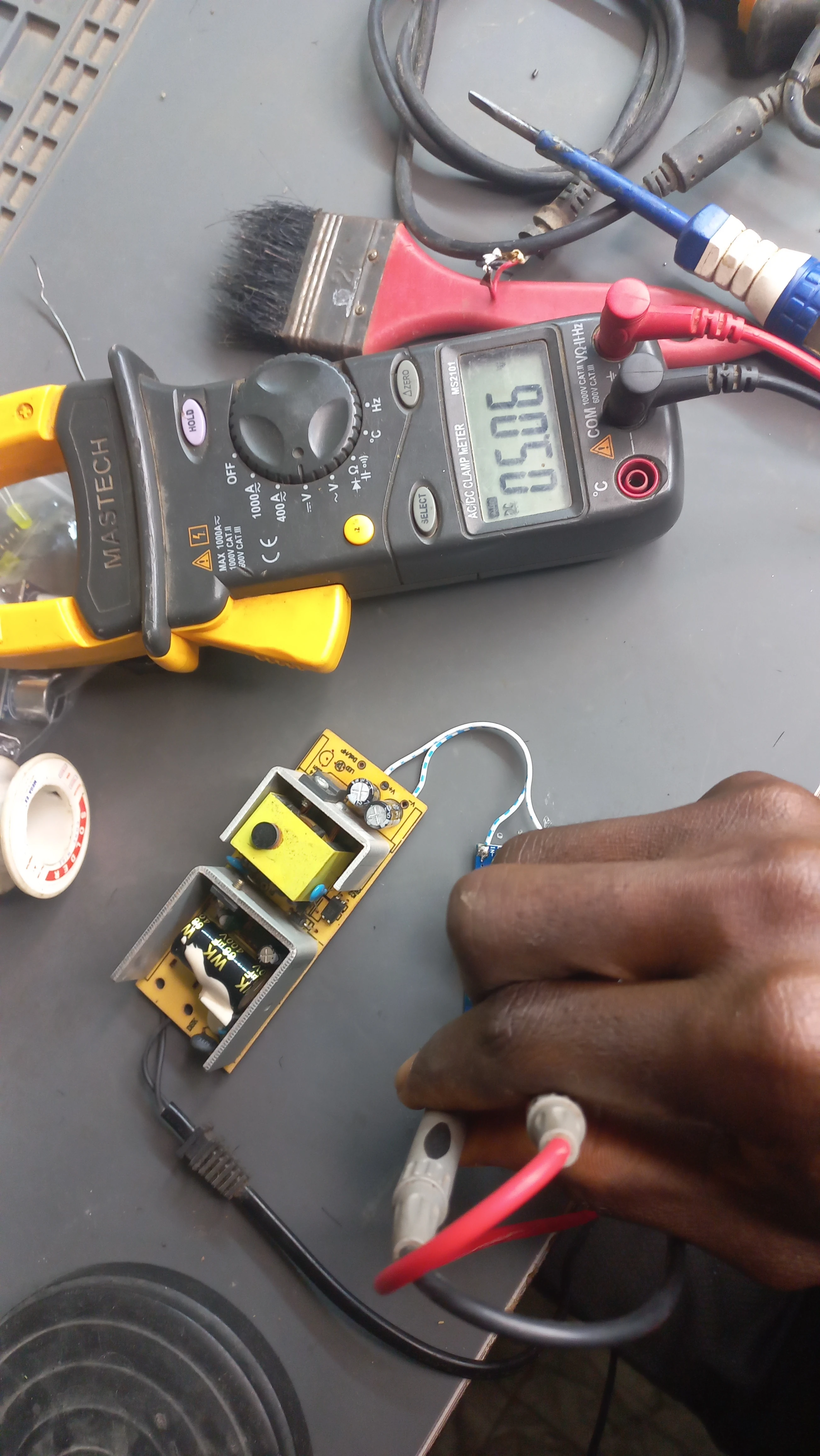
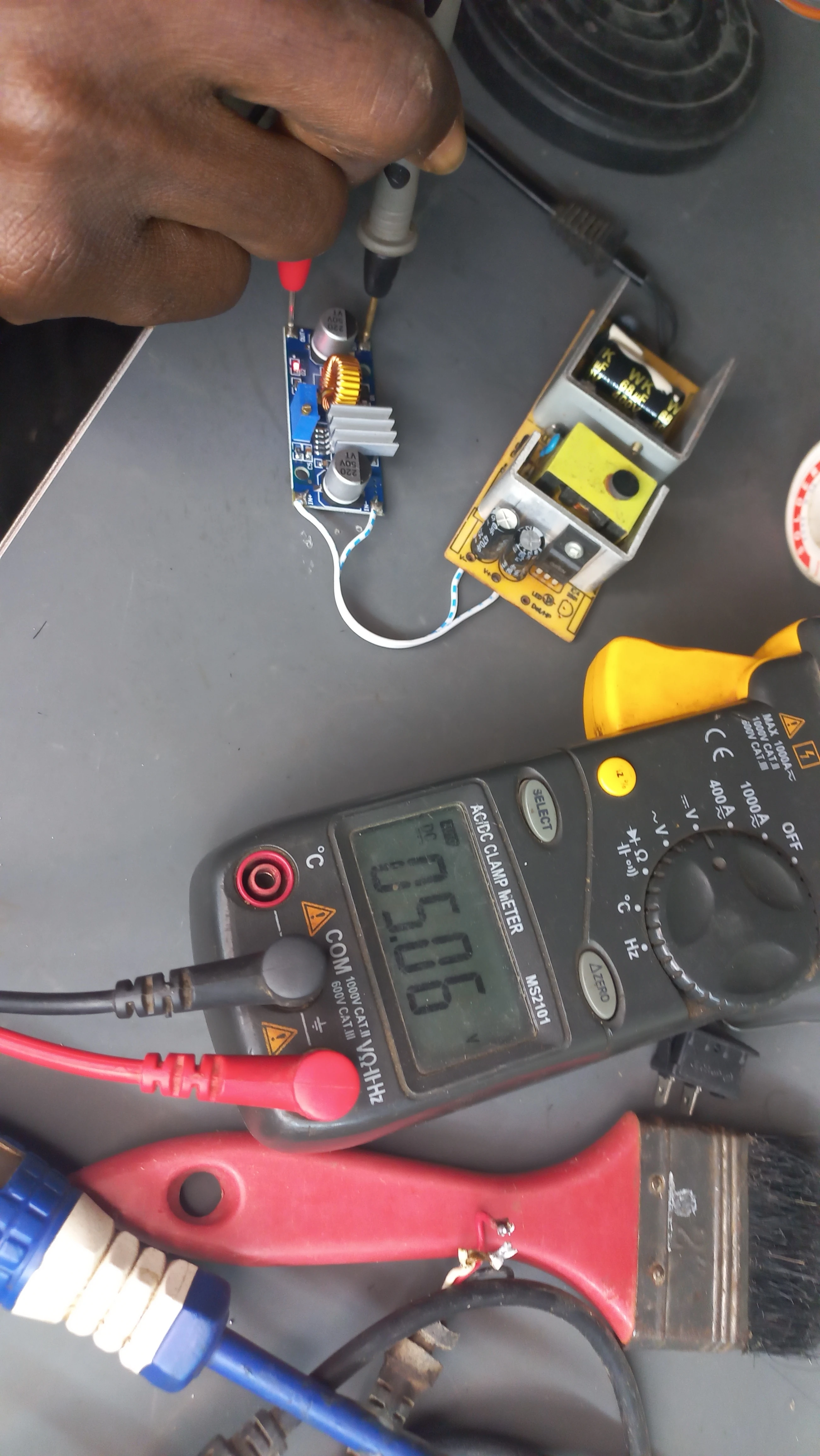
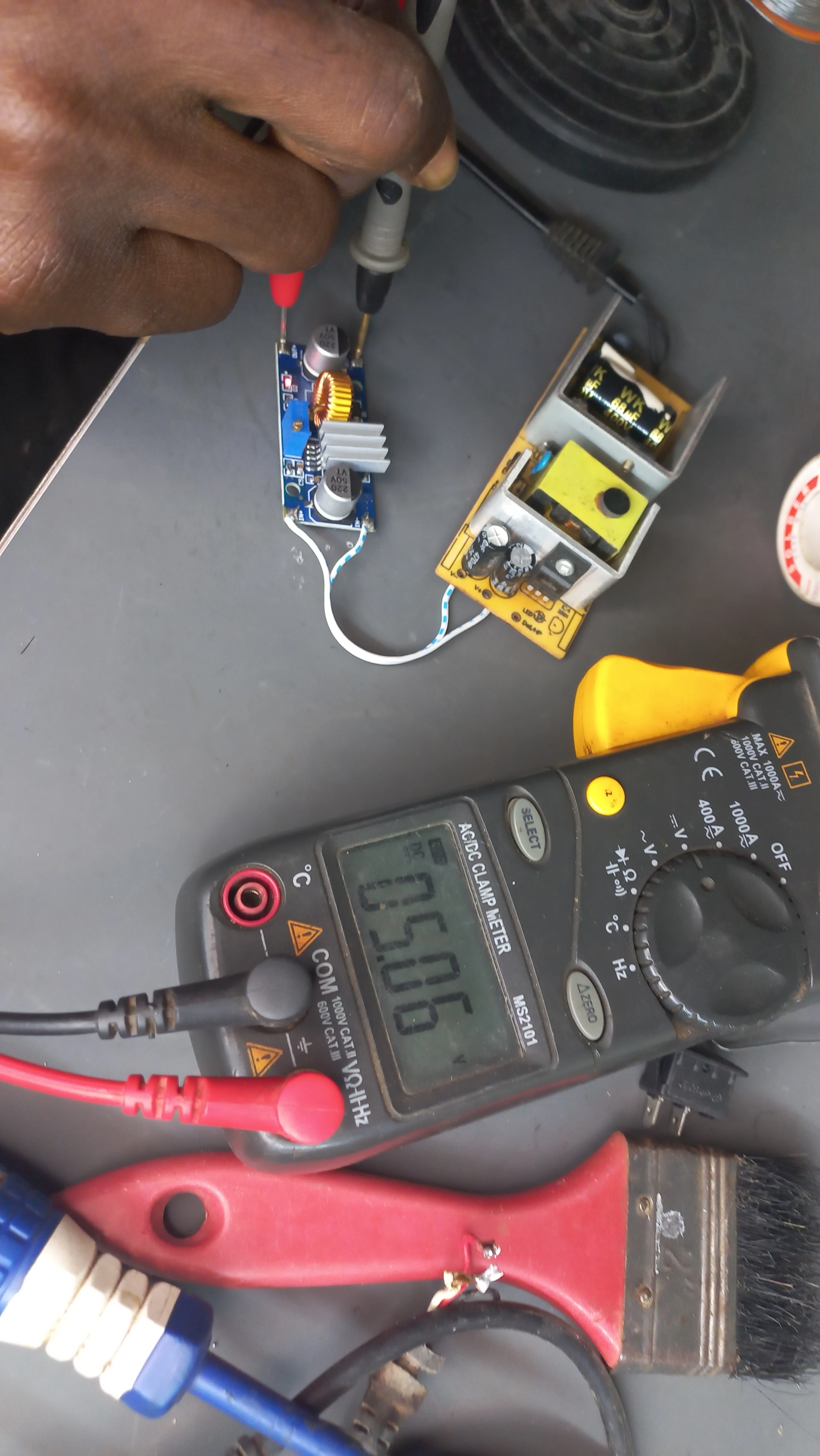
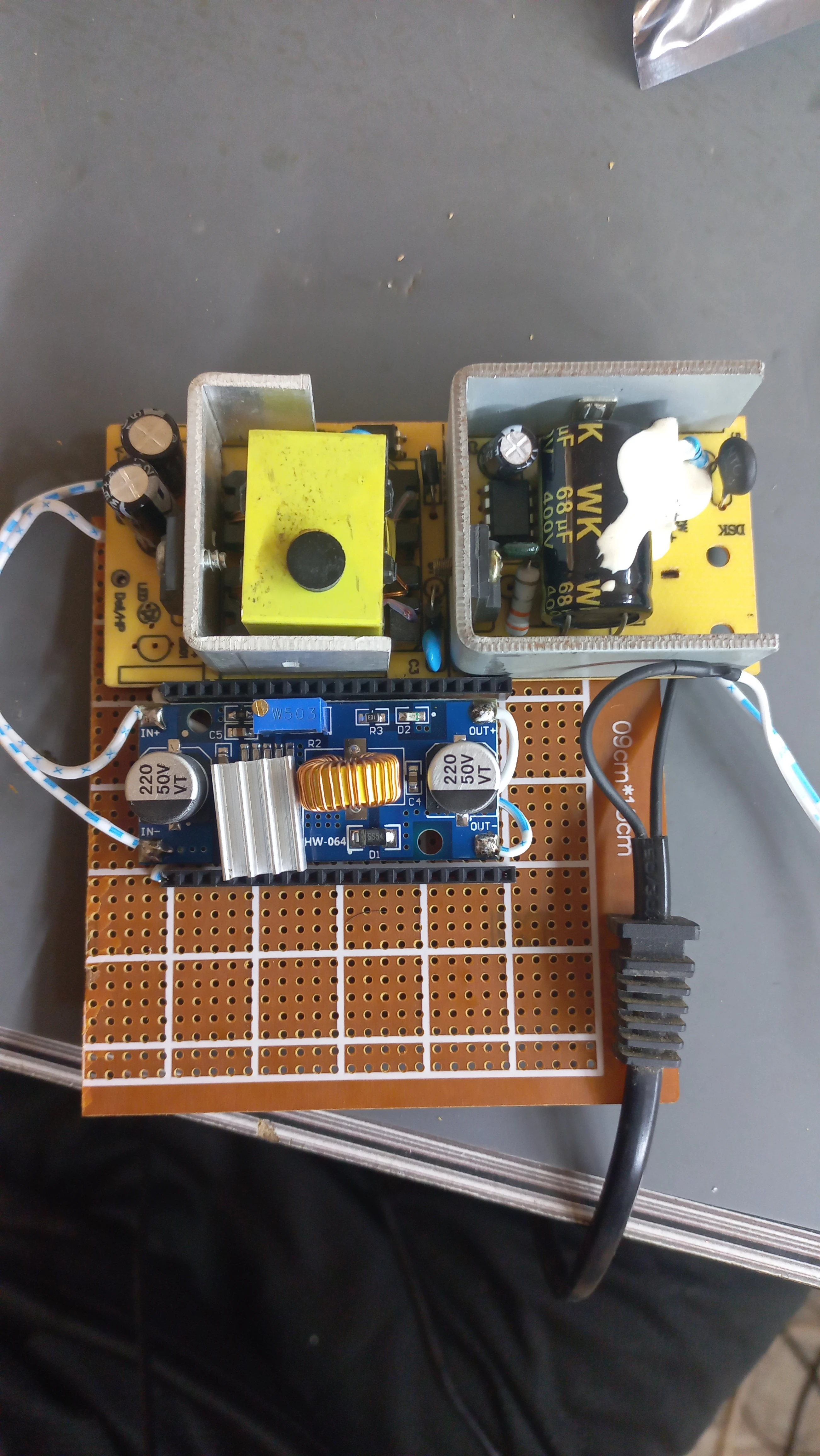
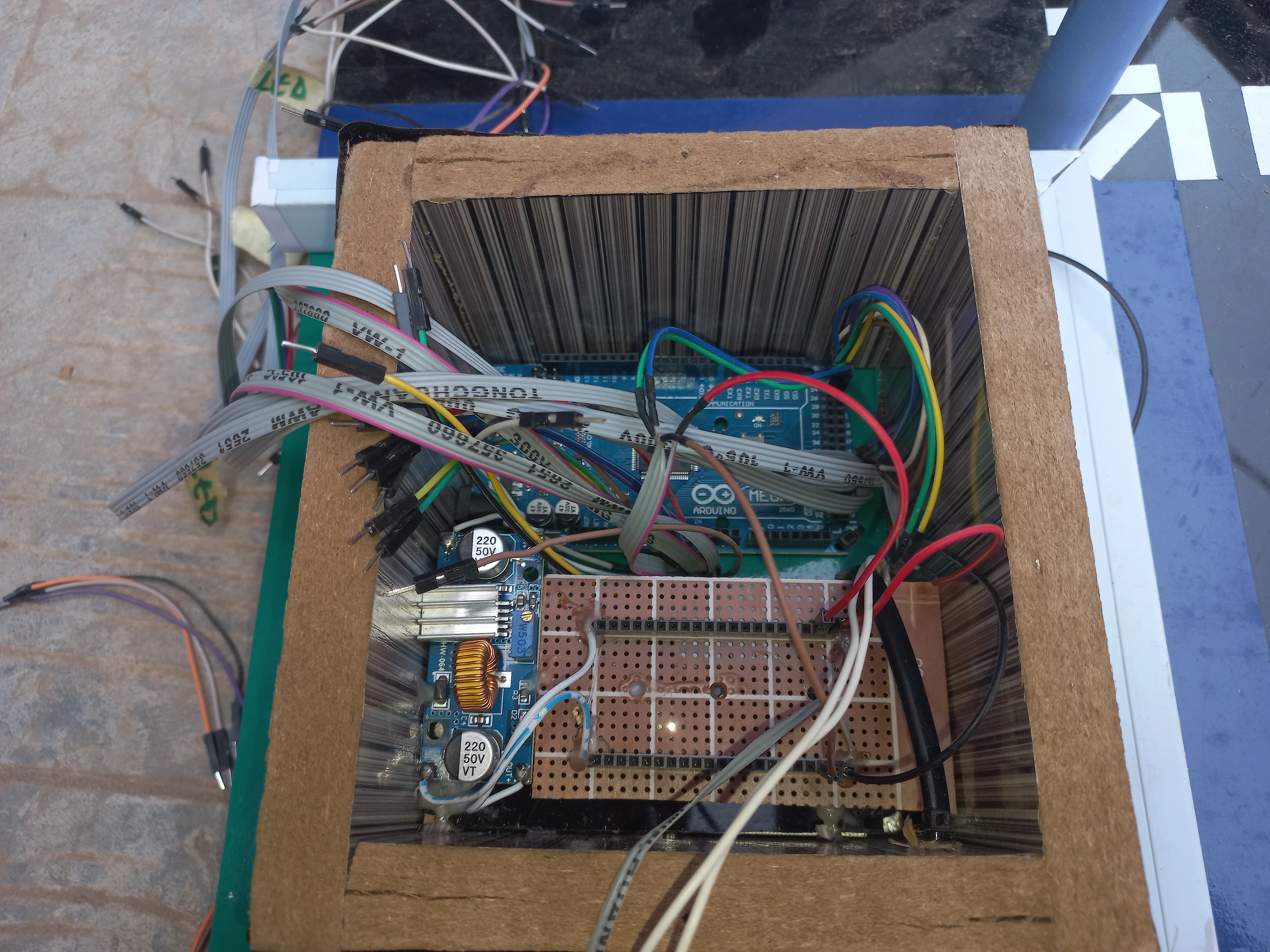
| Power Supply | 12 V DC mains adapter + DC-DC buck converter | Steps 12 V down to 5 V for Arduino and sensor rails |
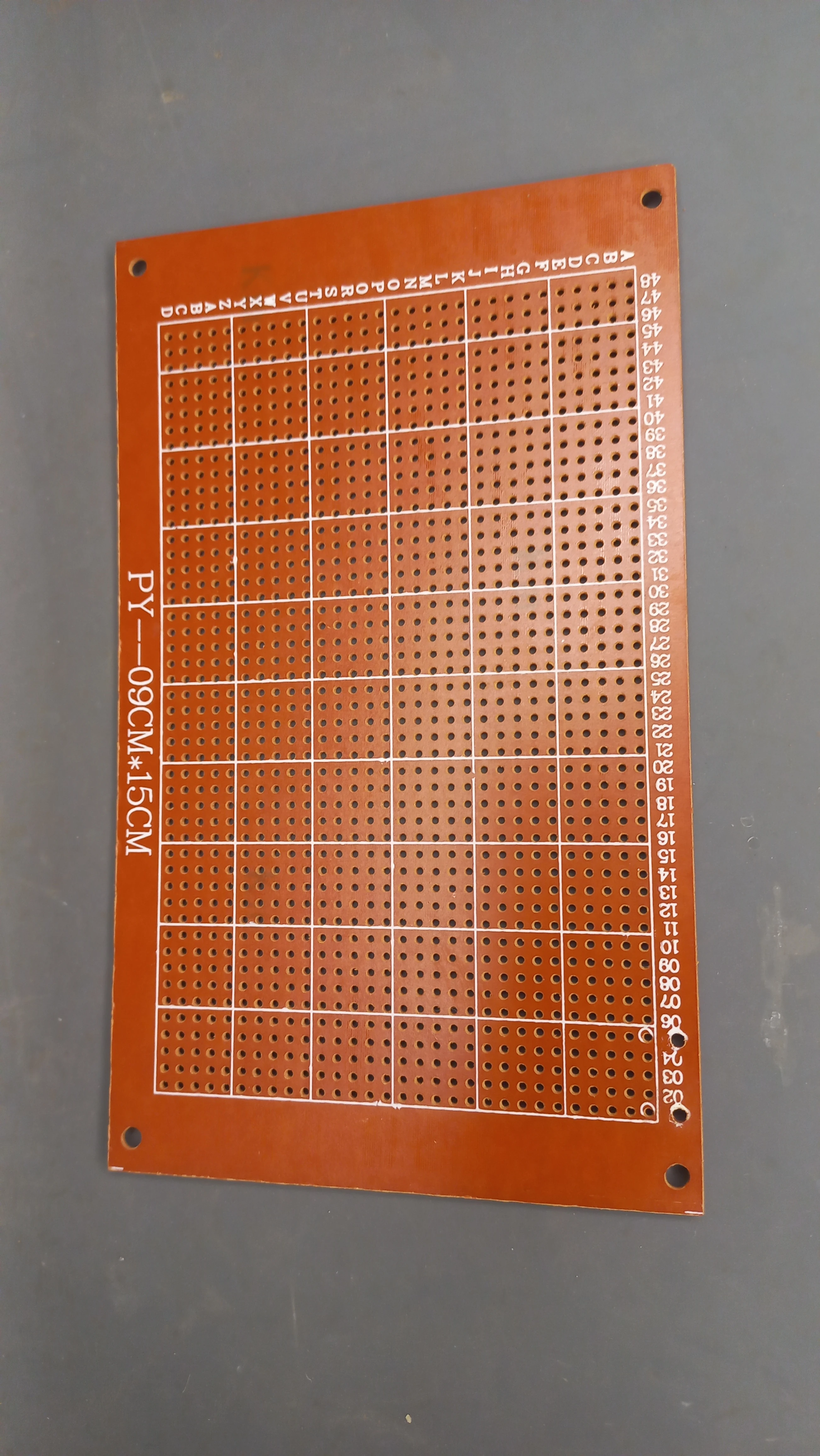
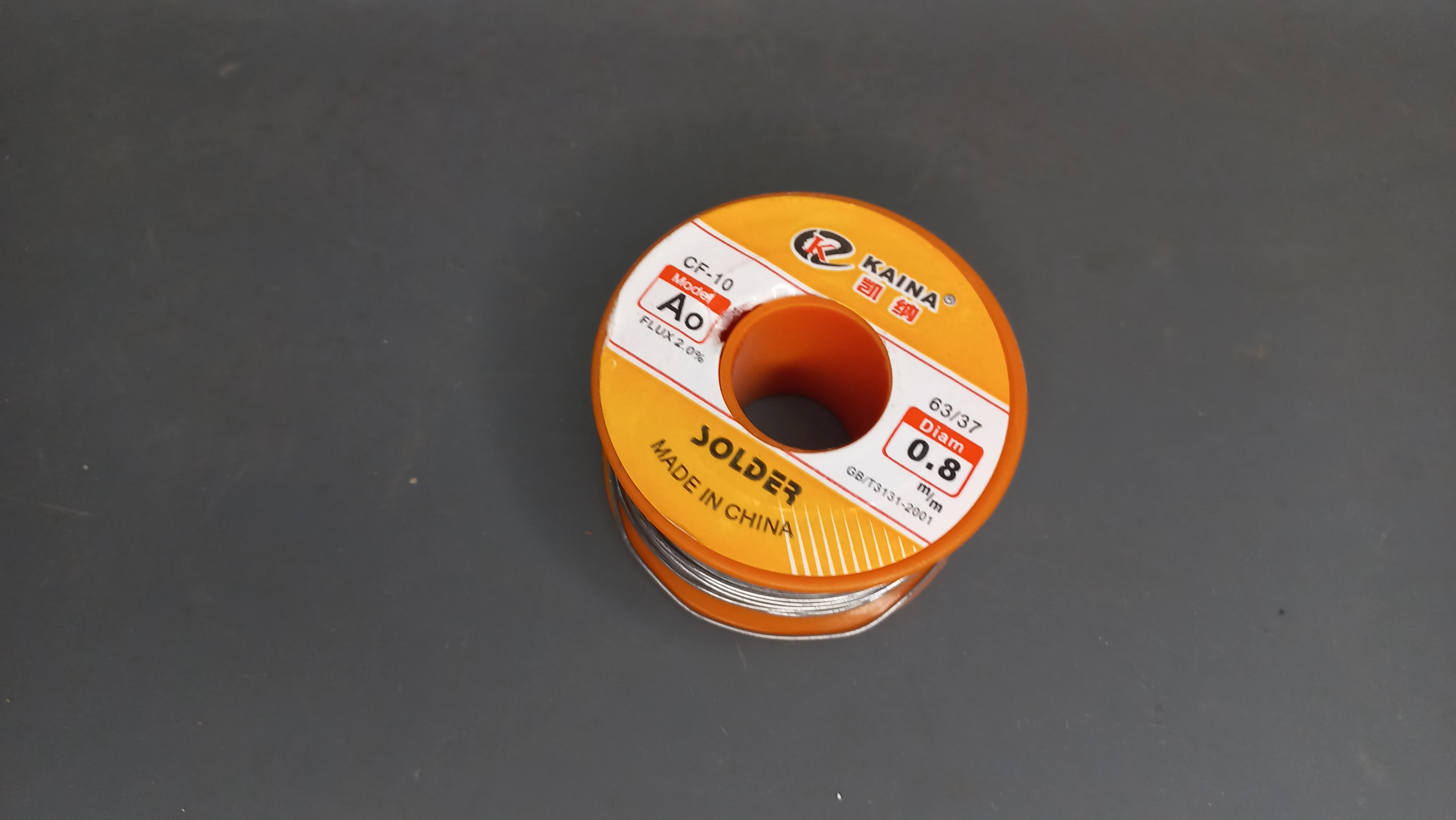
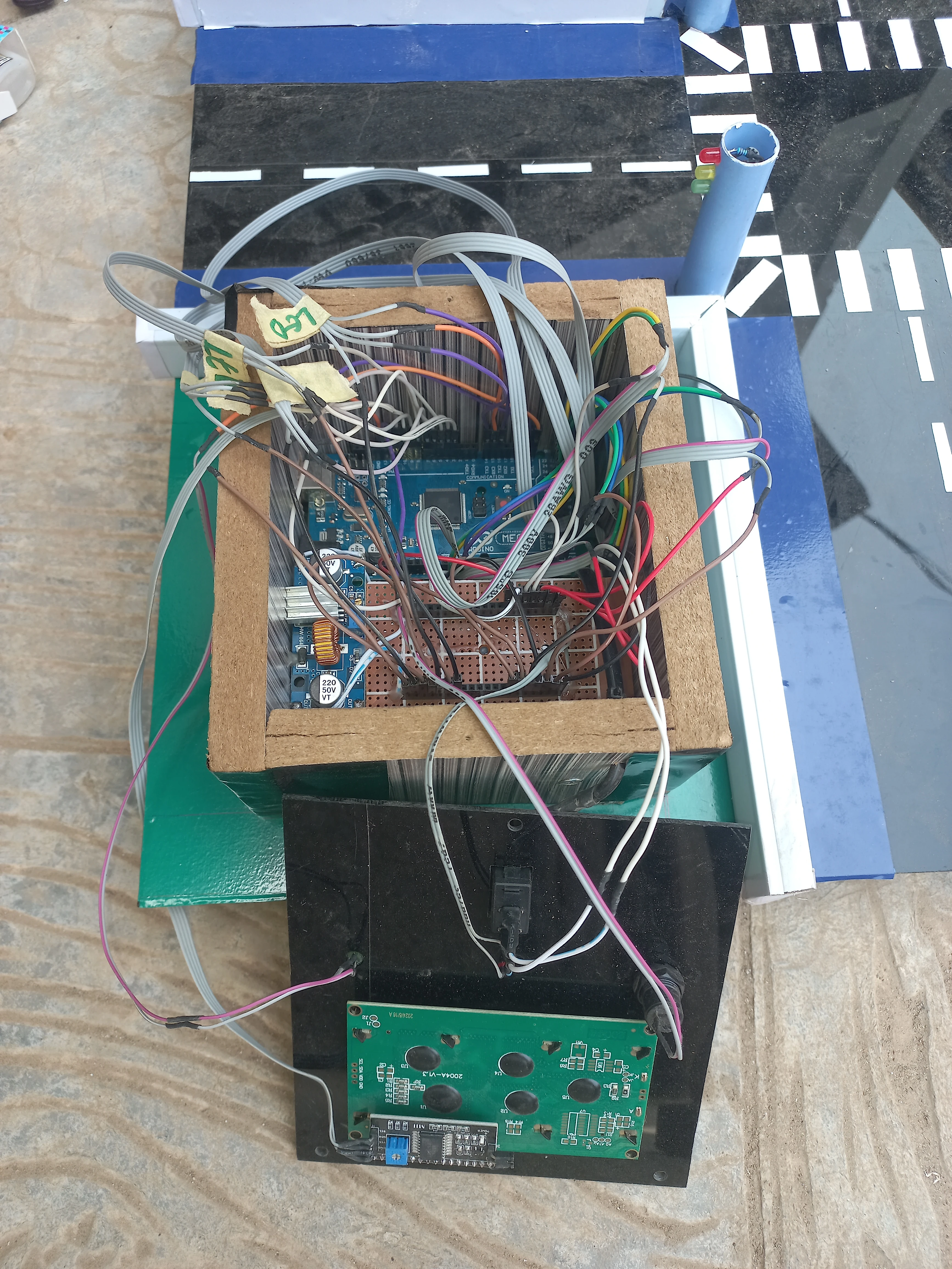
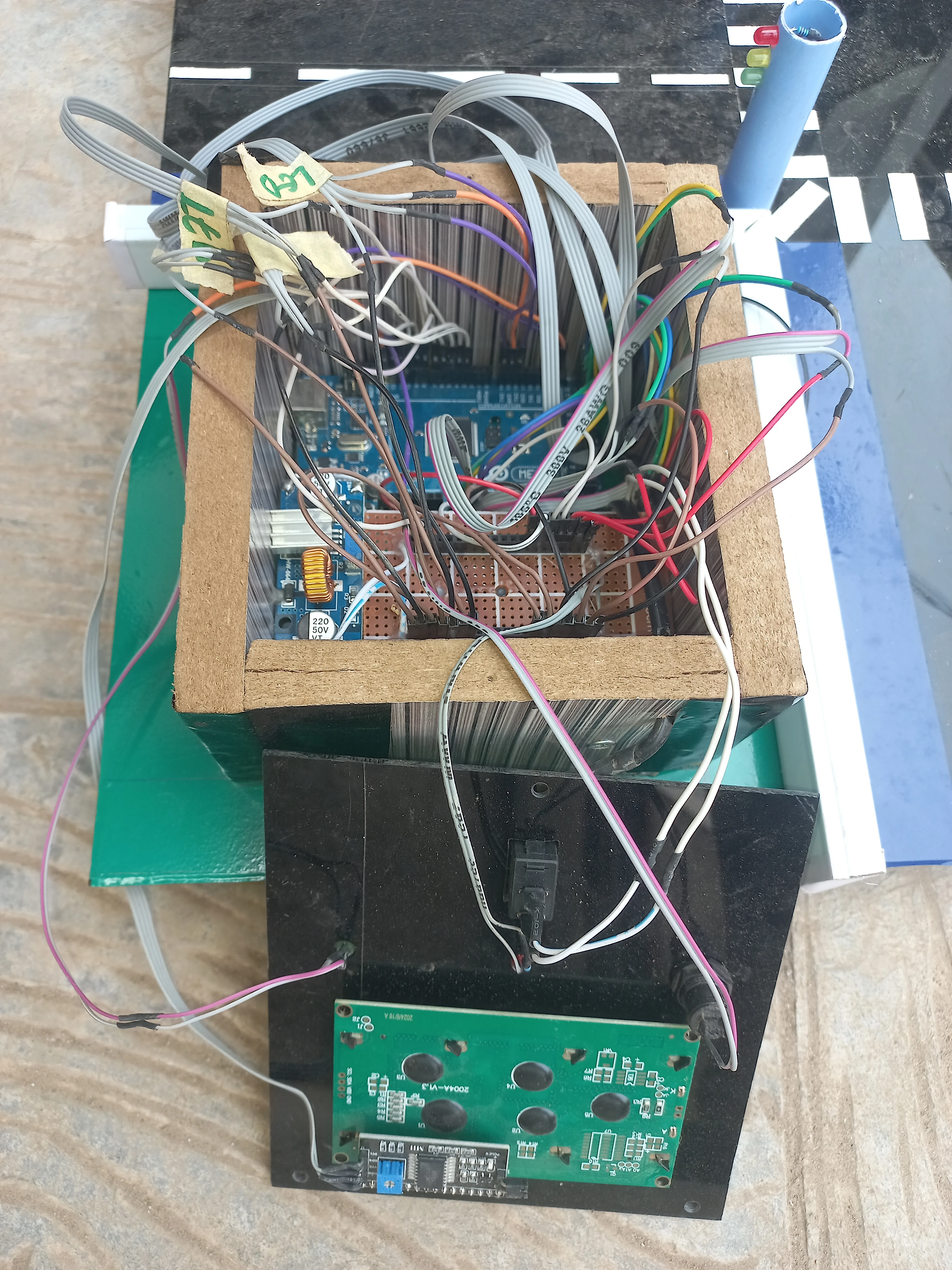
| Perfboard PCB | 9 cm ×15 cm copper perfboard | Permanent soldered integration of buck converter and connectors |
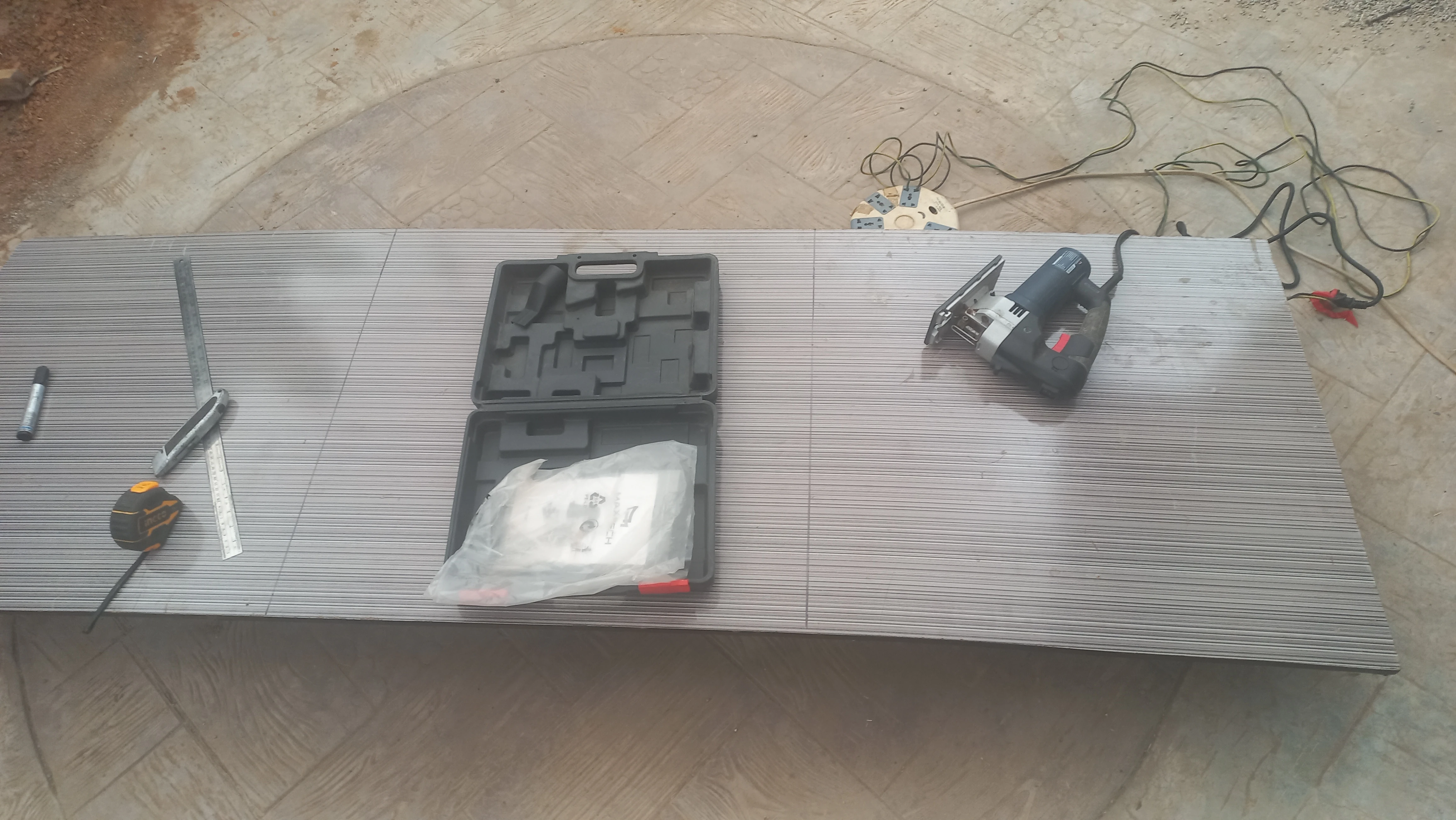
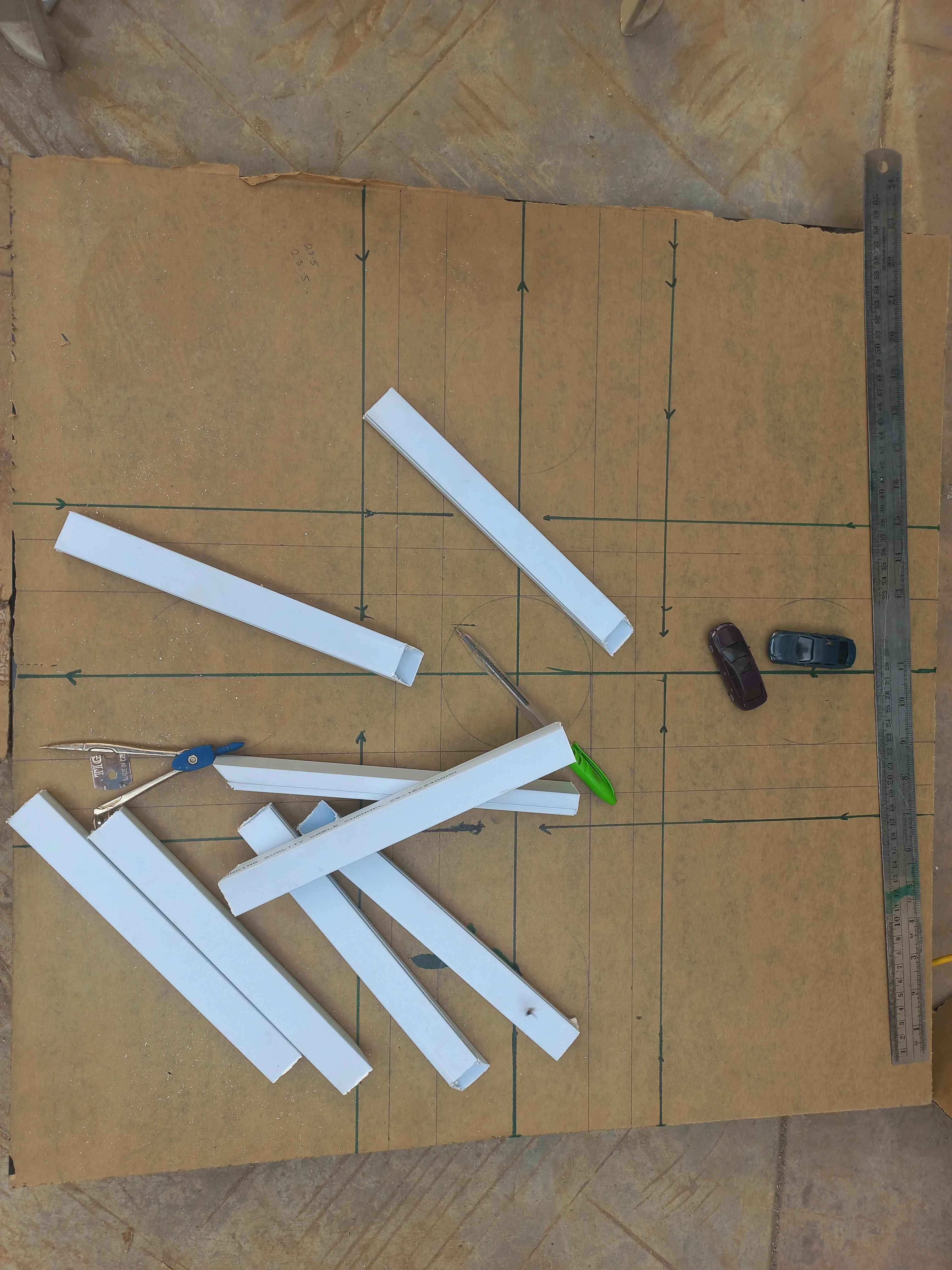
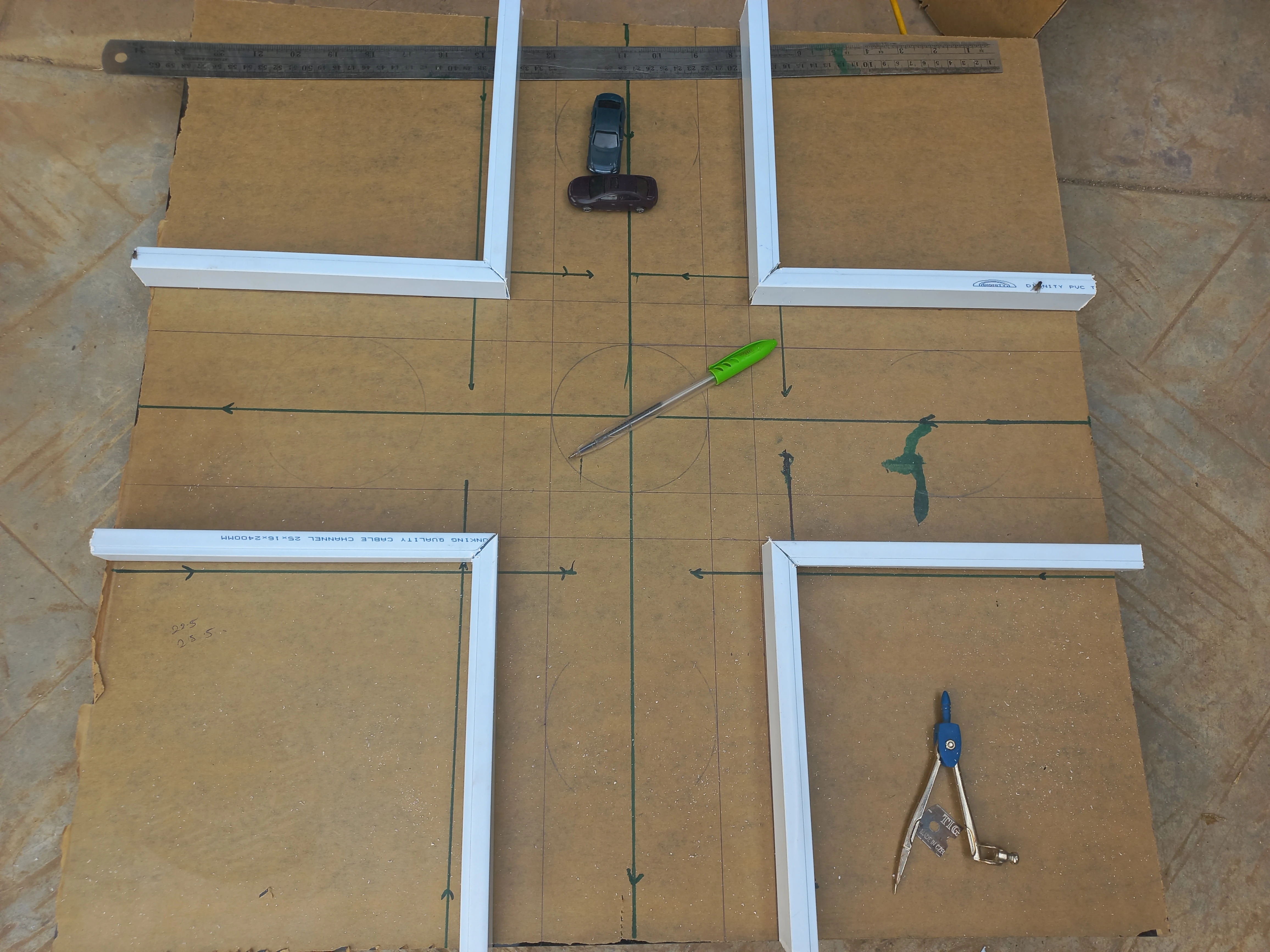
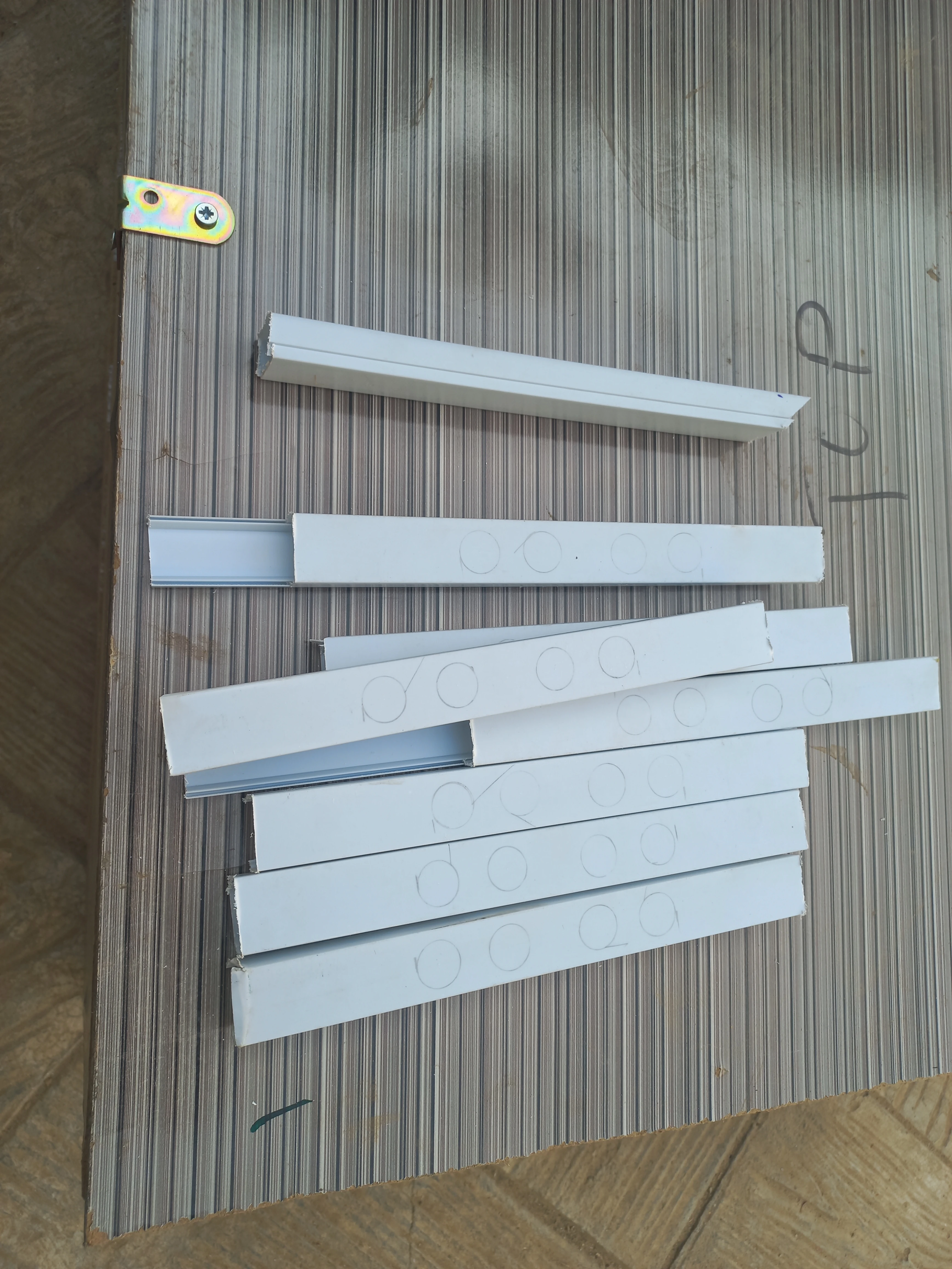
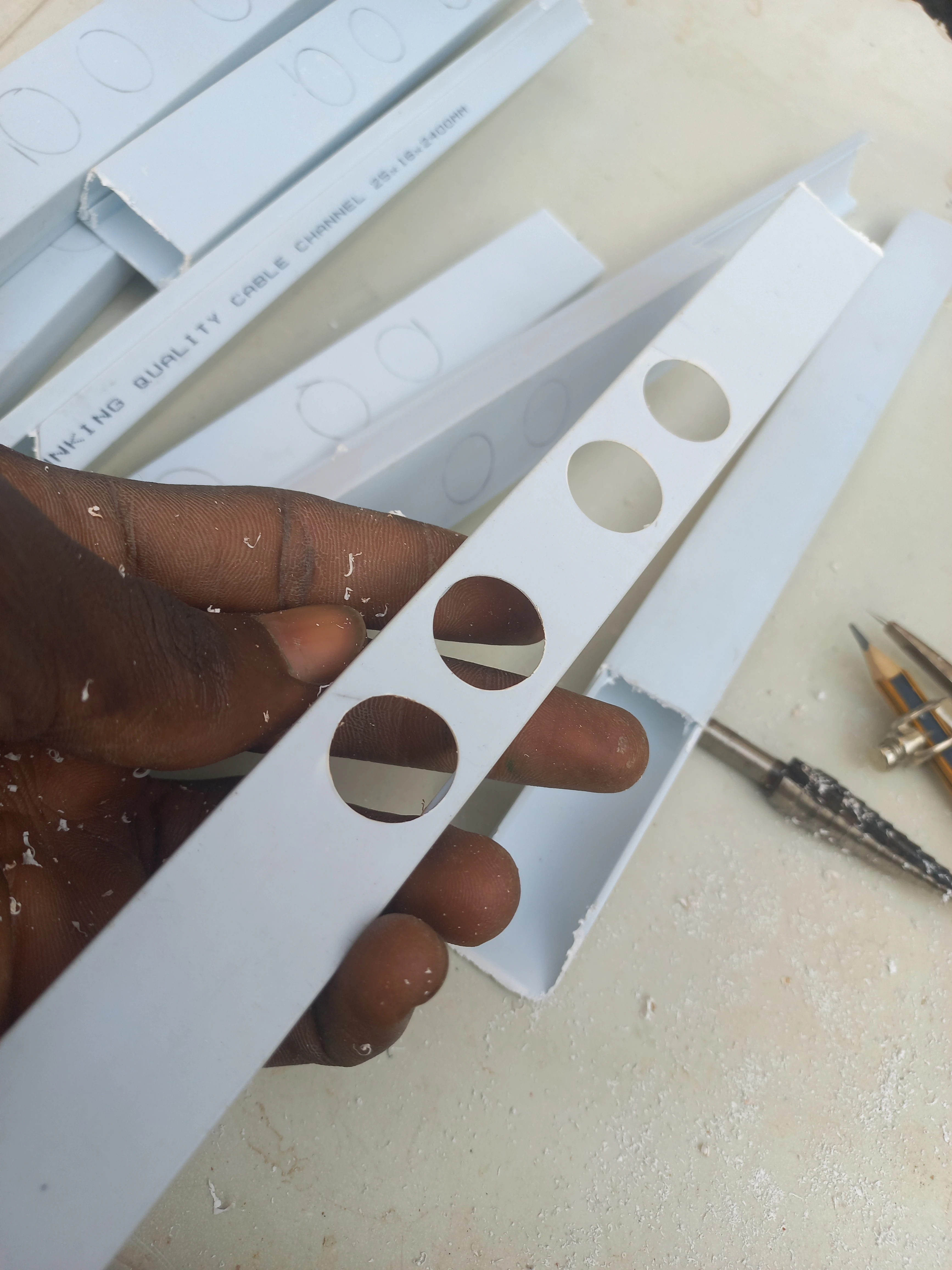
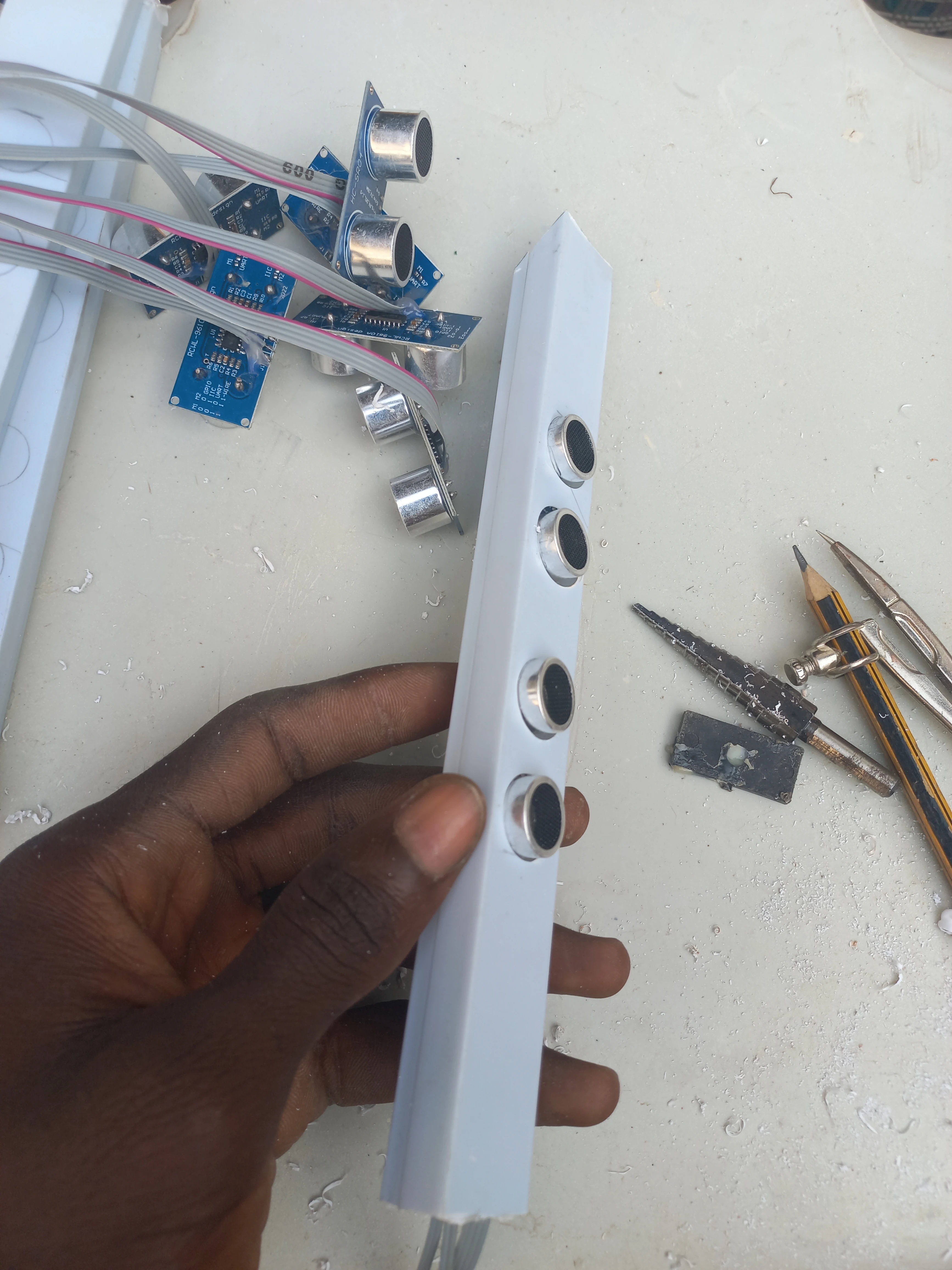
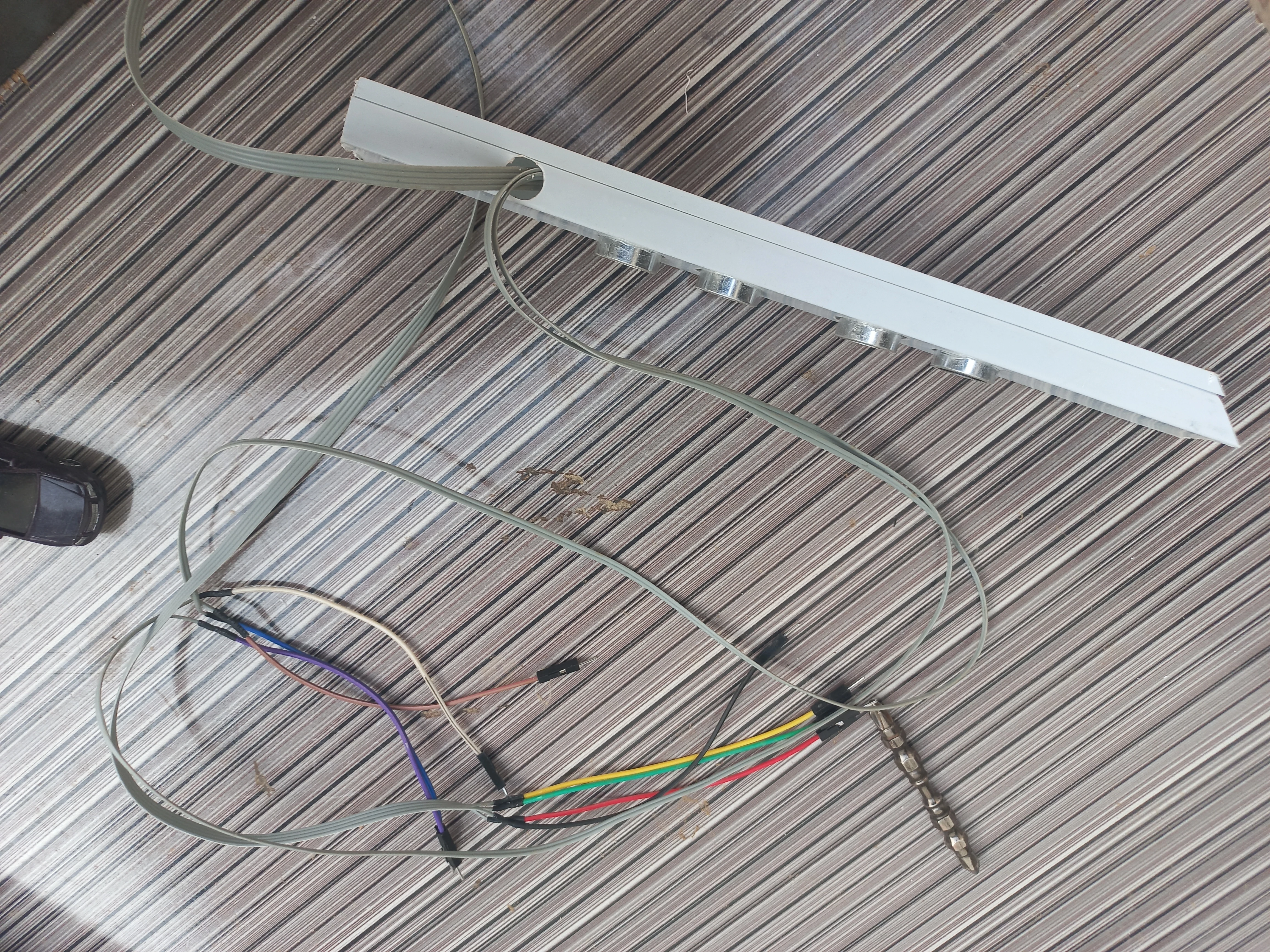
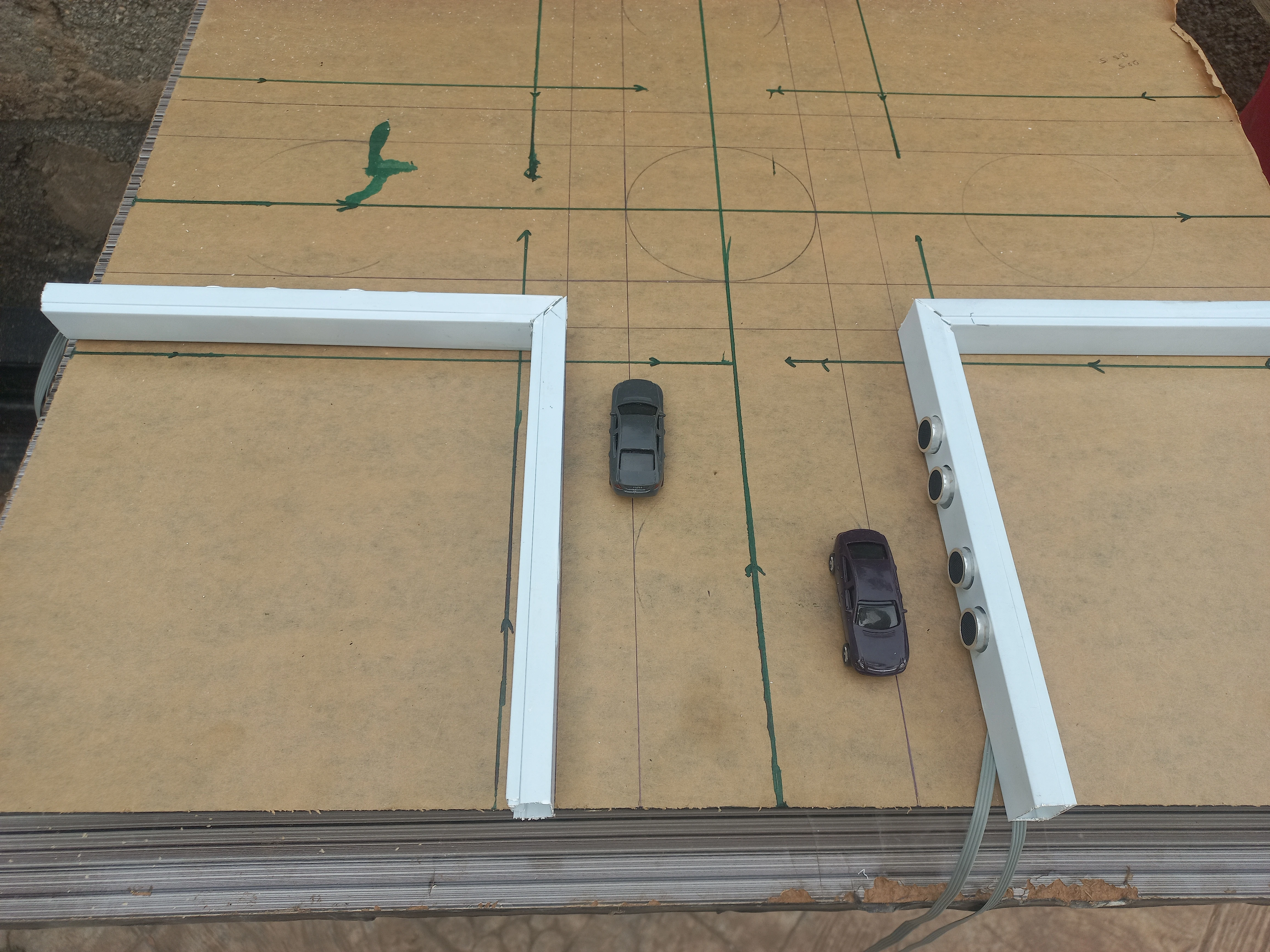
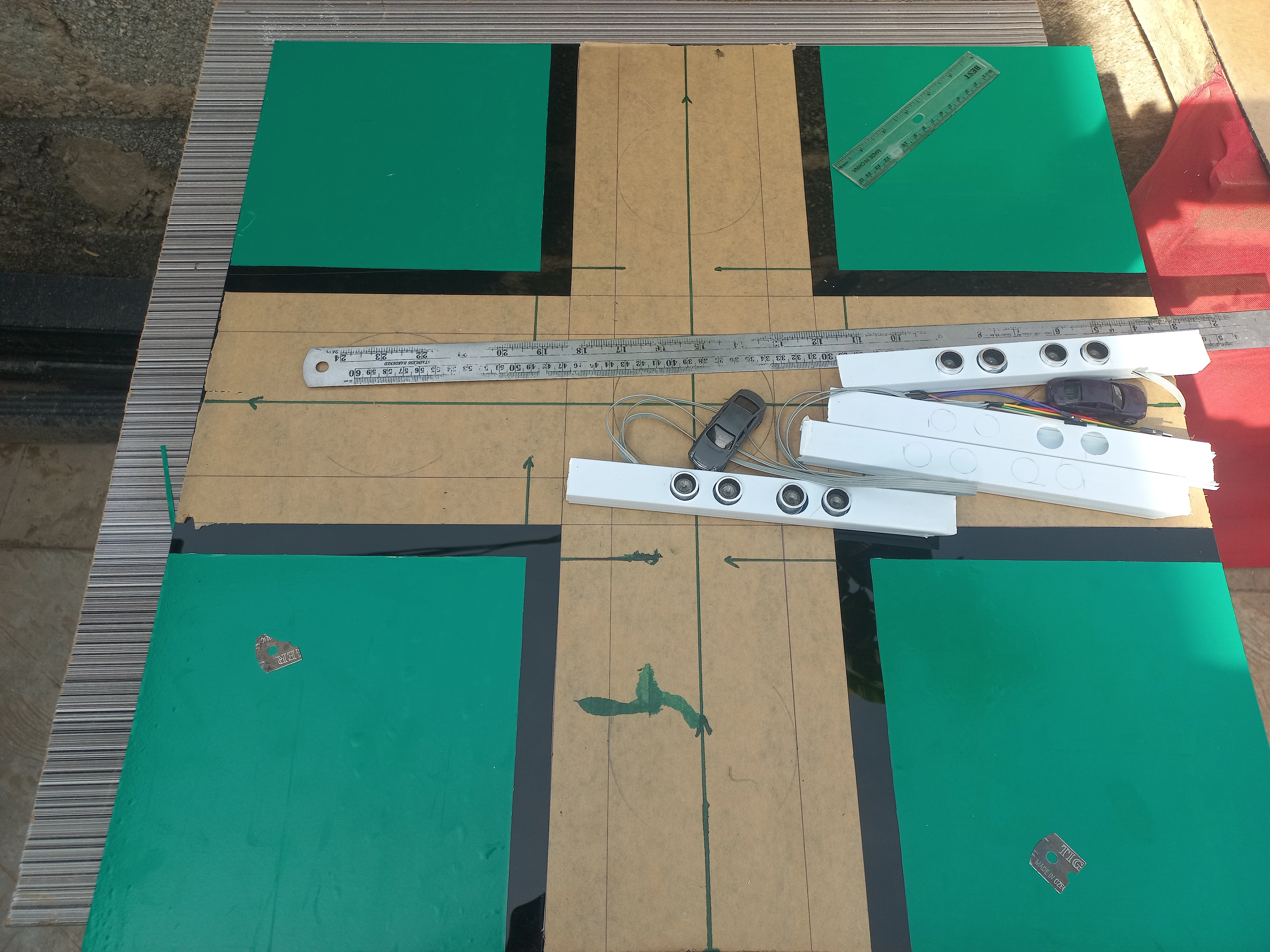
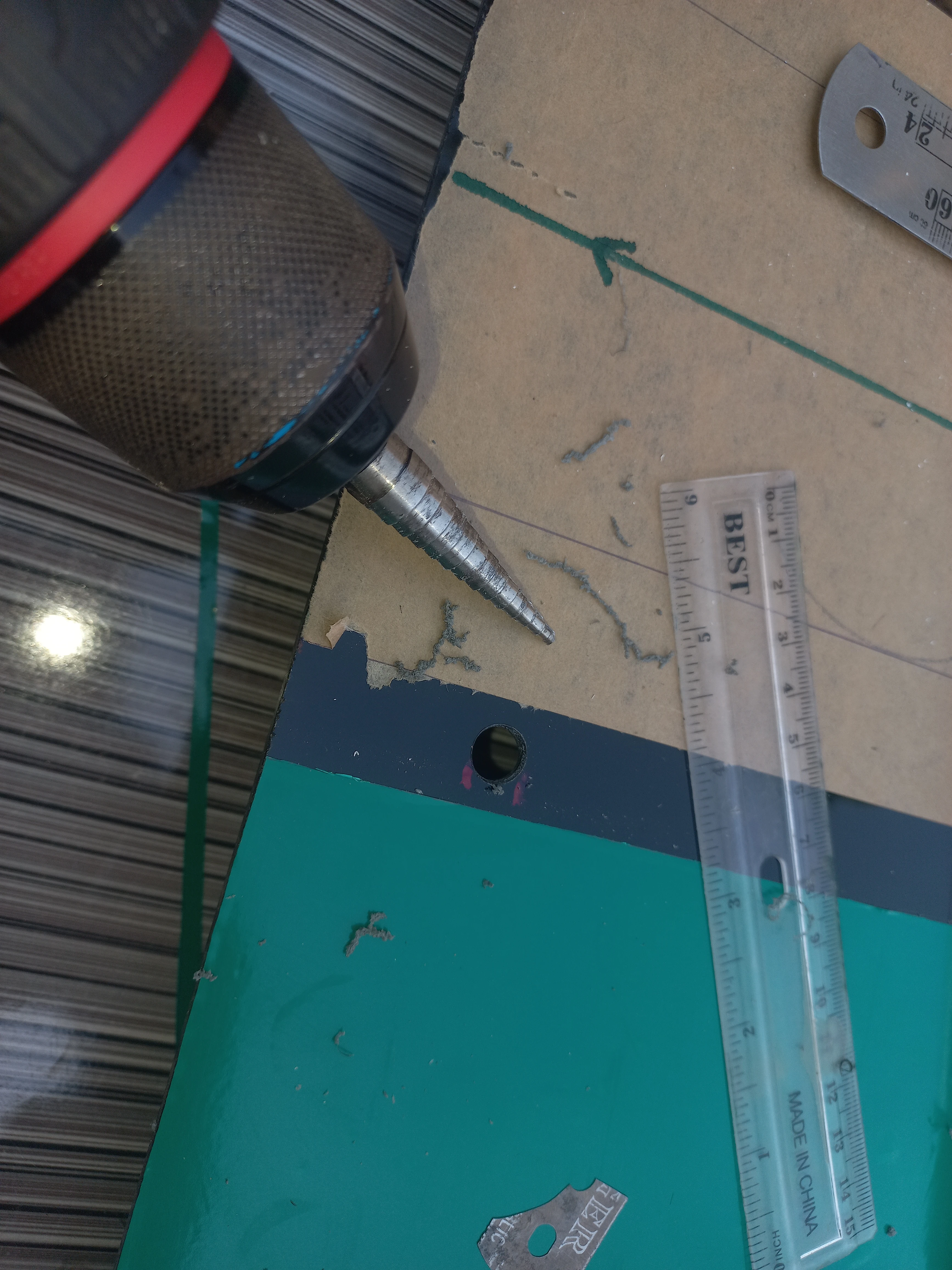
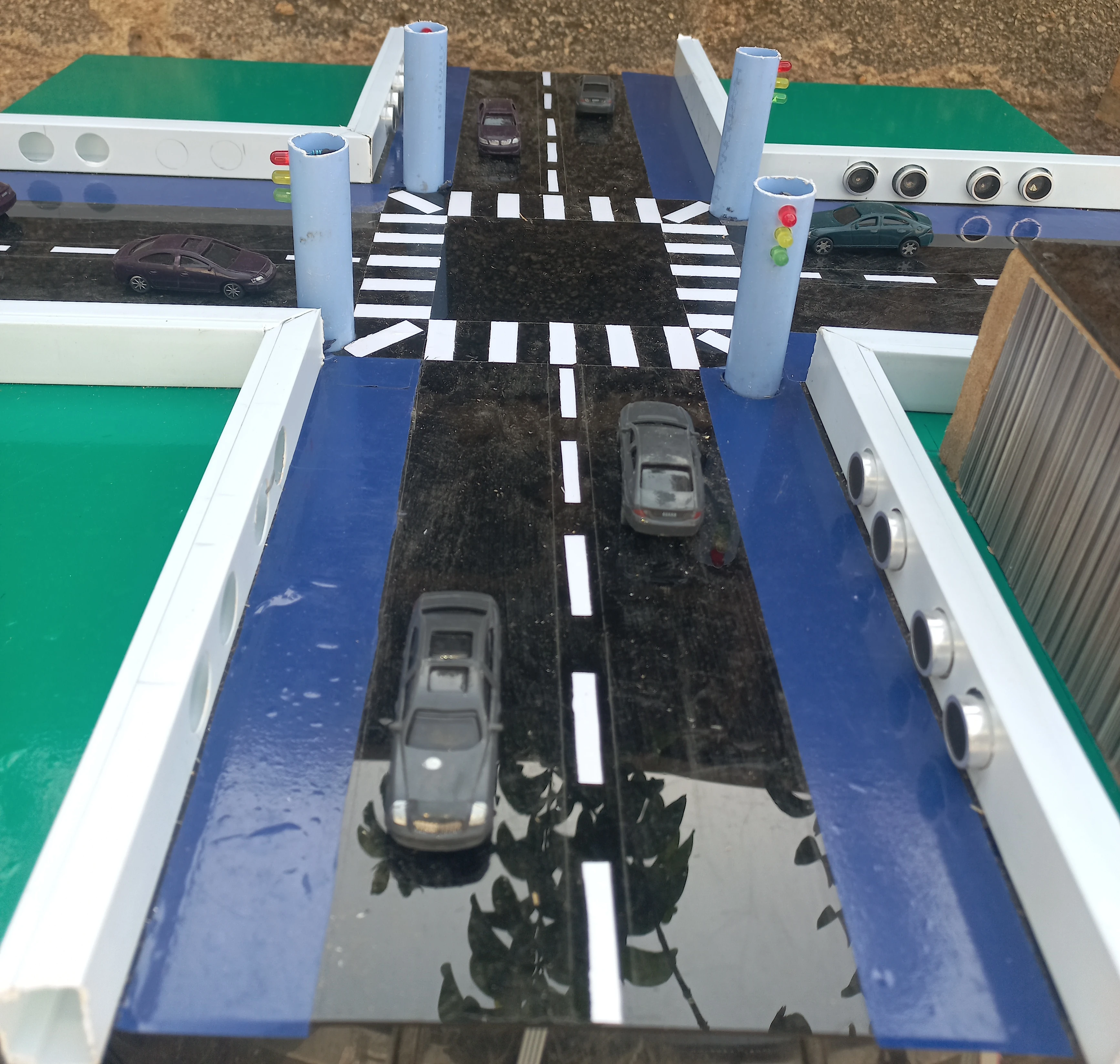
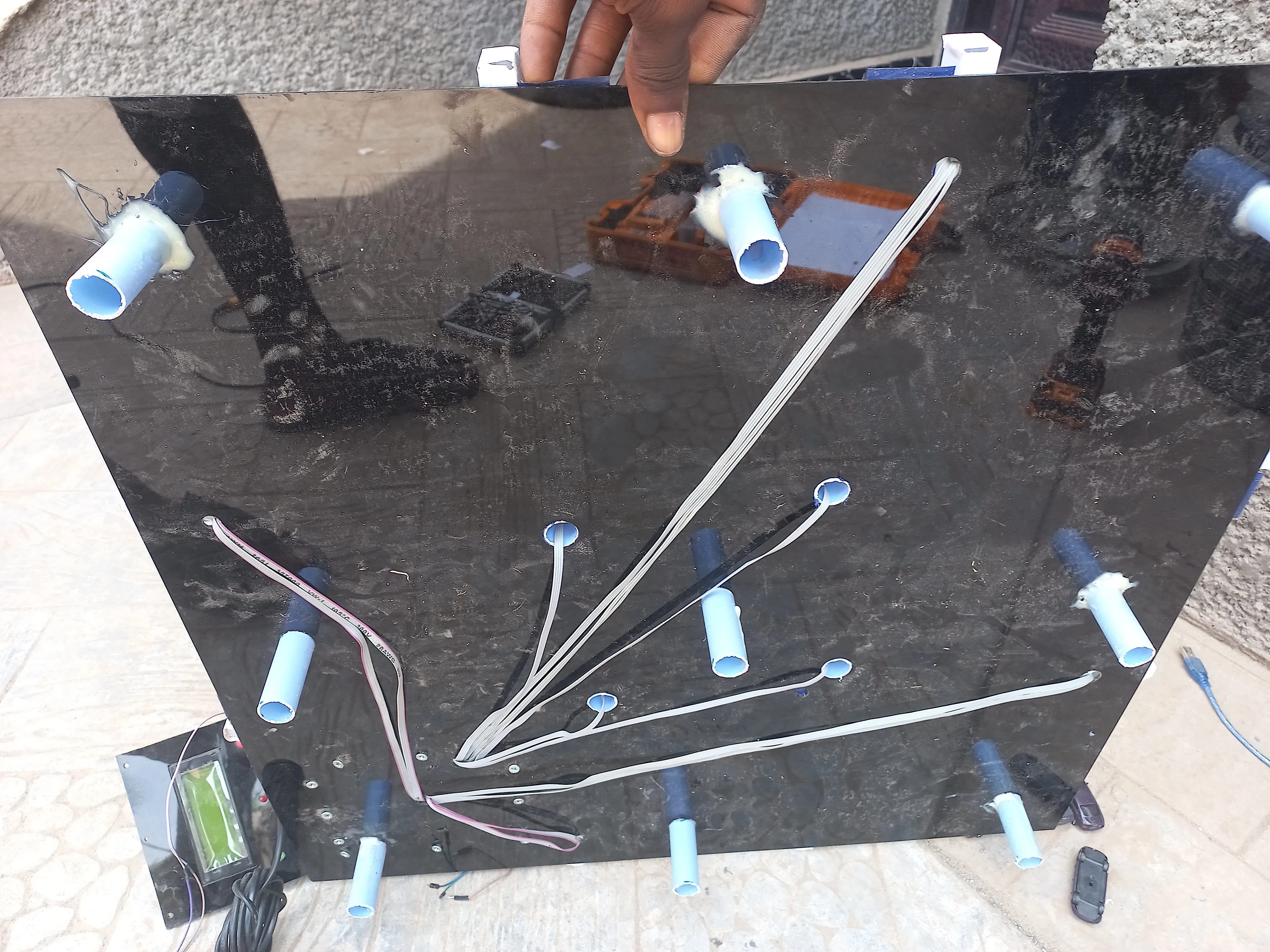
| Cable Trunking | PVC cable trunking strips (road channel routing) | Conceals and routes sensor and LED wiring beneath road surface |
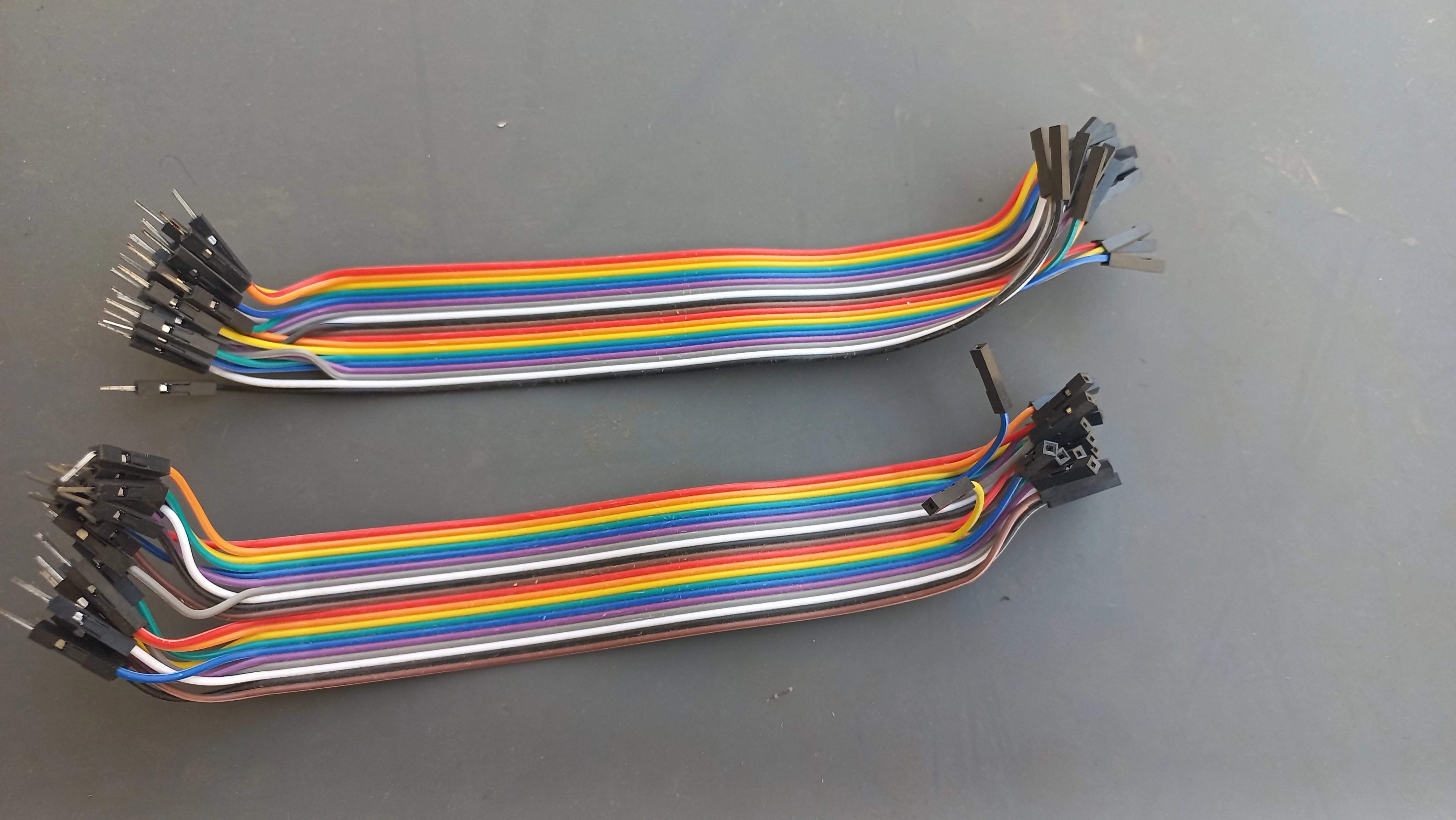
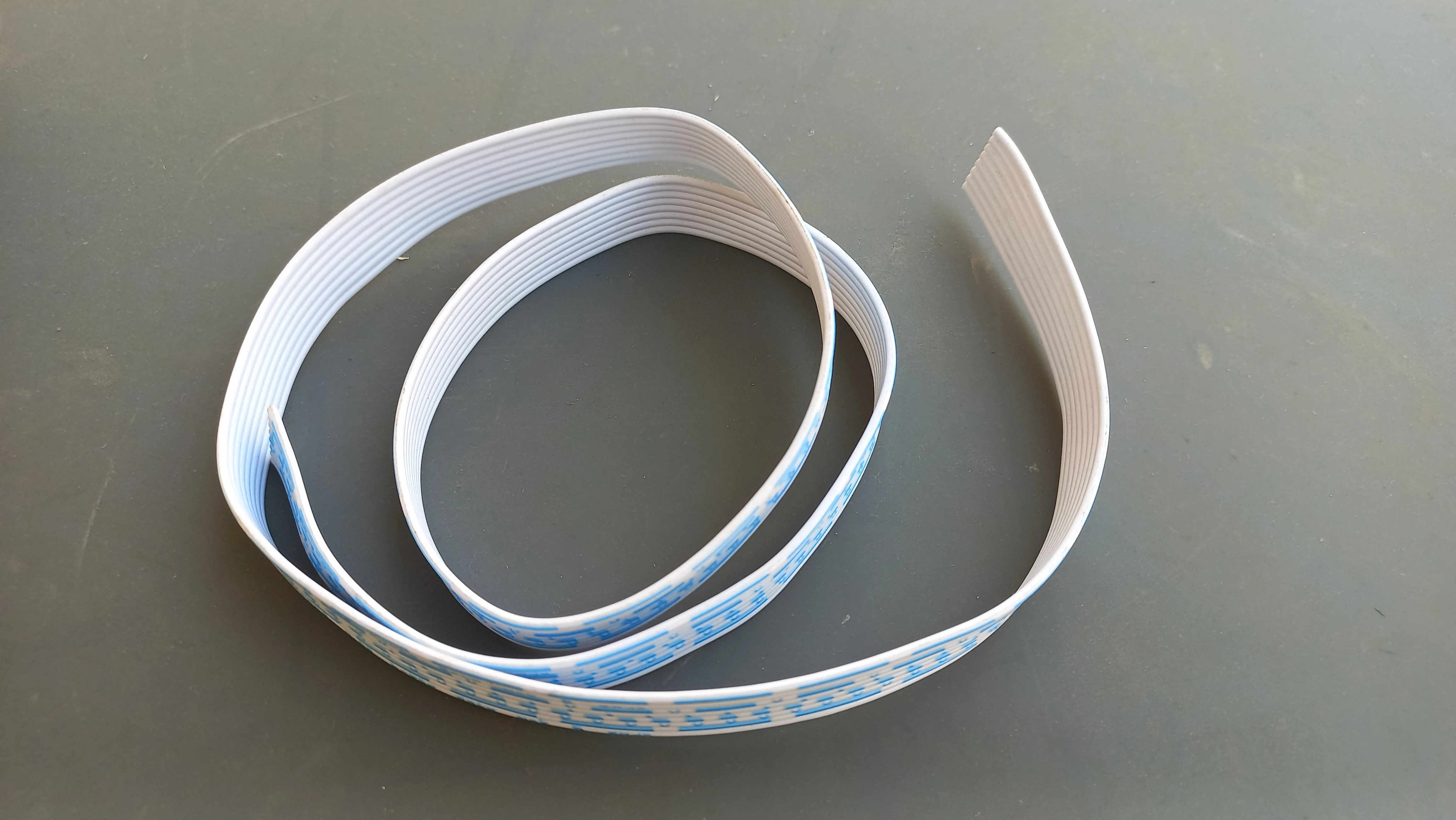
| Ribbon Cable | Multi-core ribbon cable | Wiring harnesses from sensor bars to Arduino Mega |
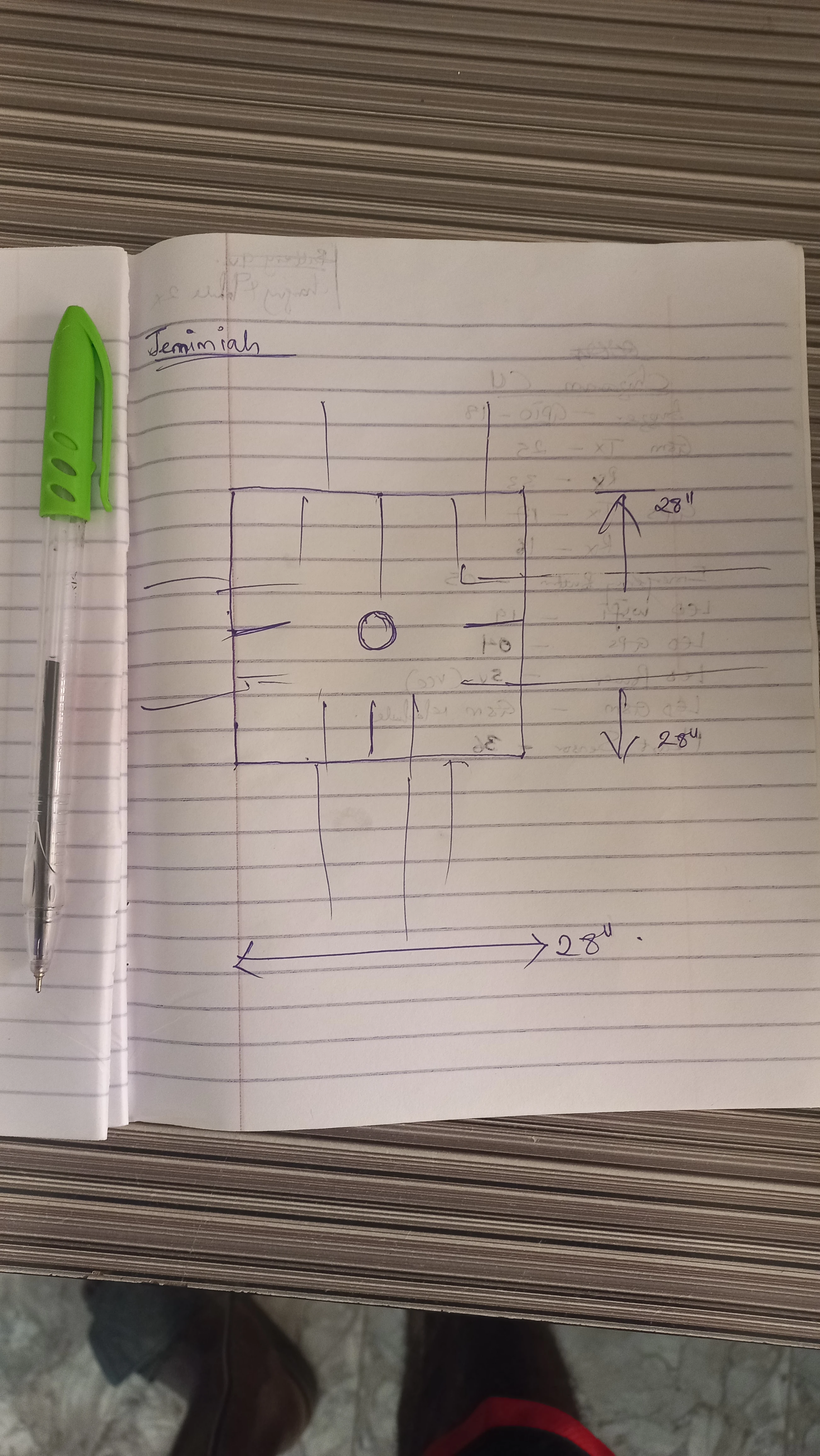
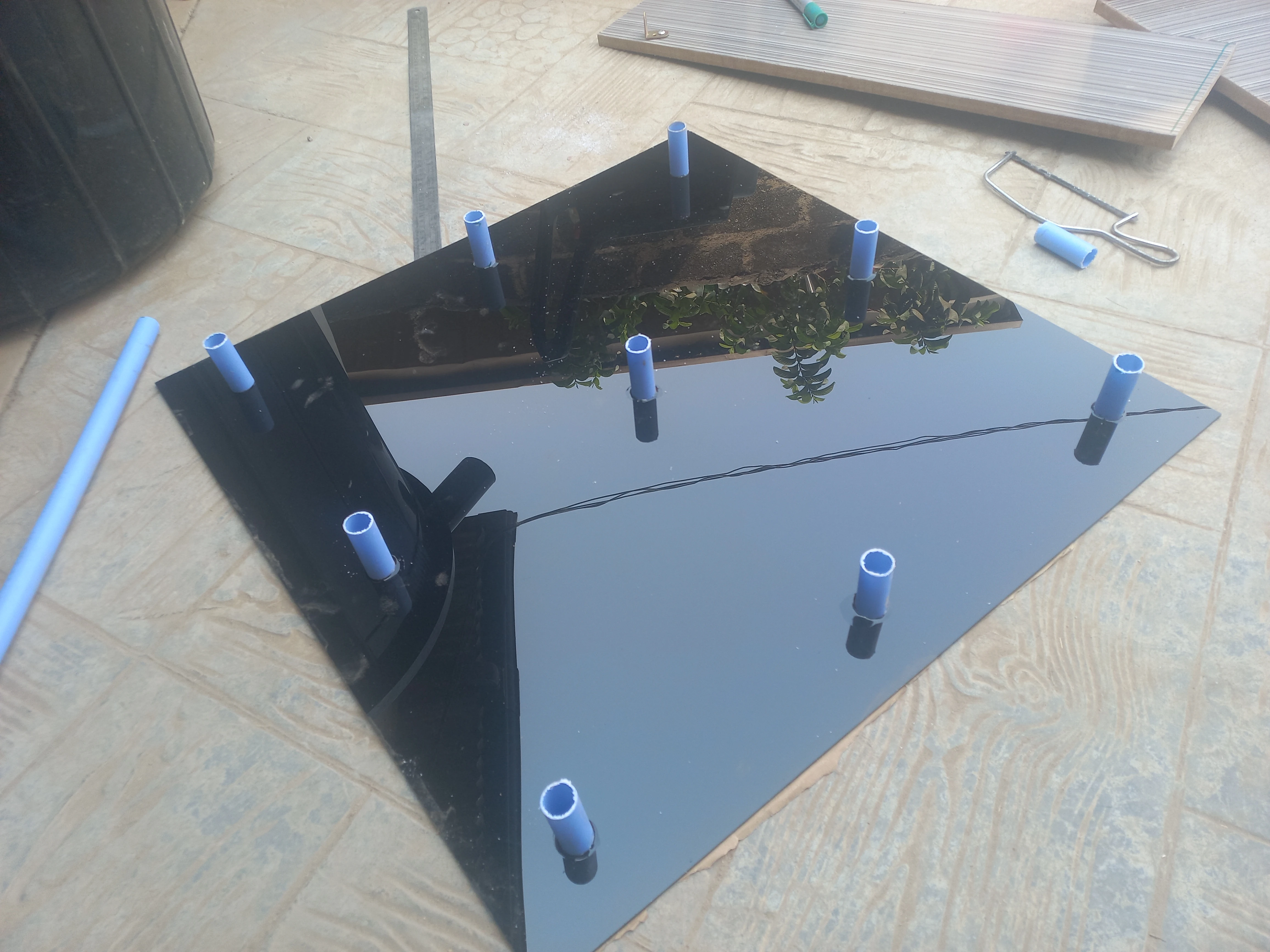
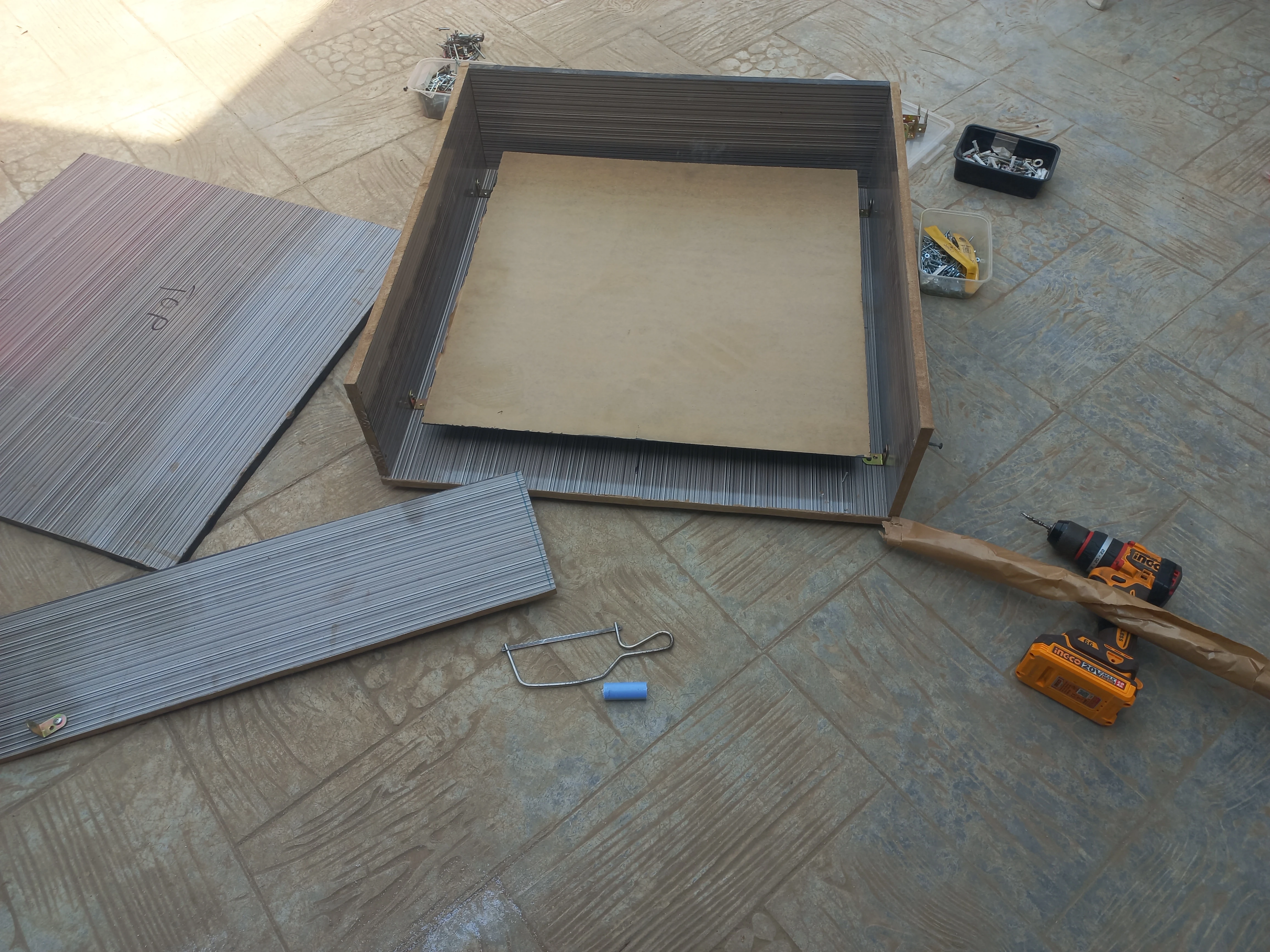
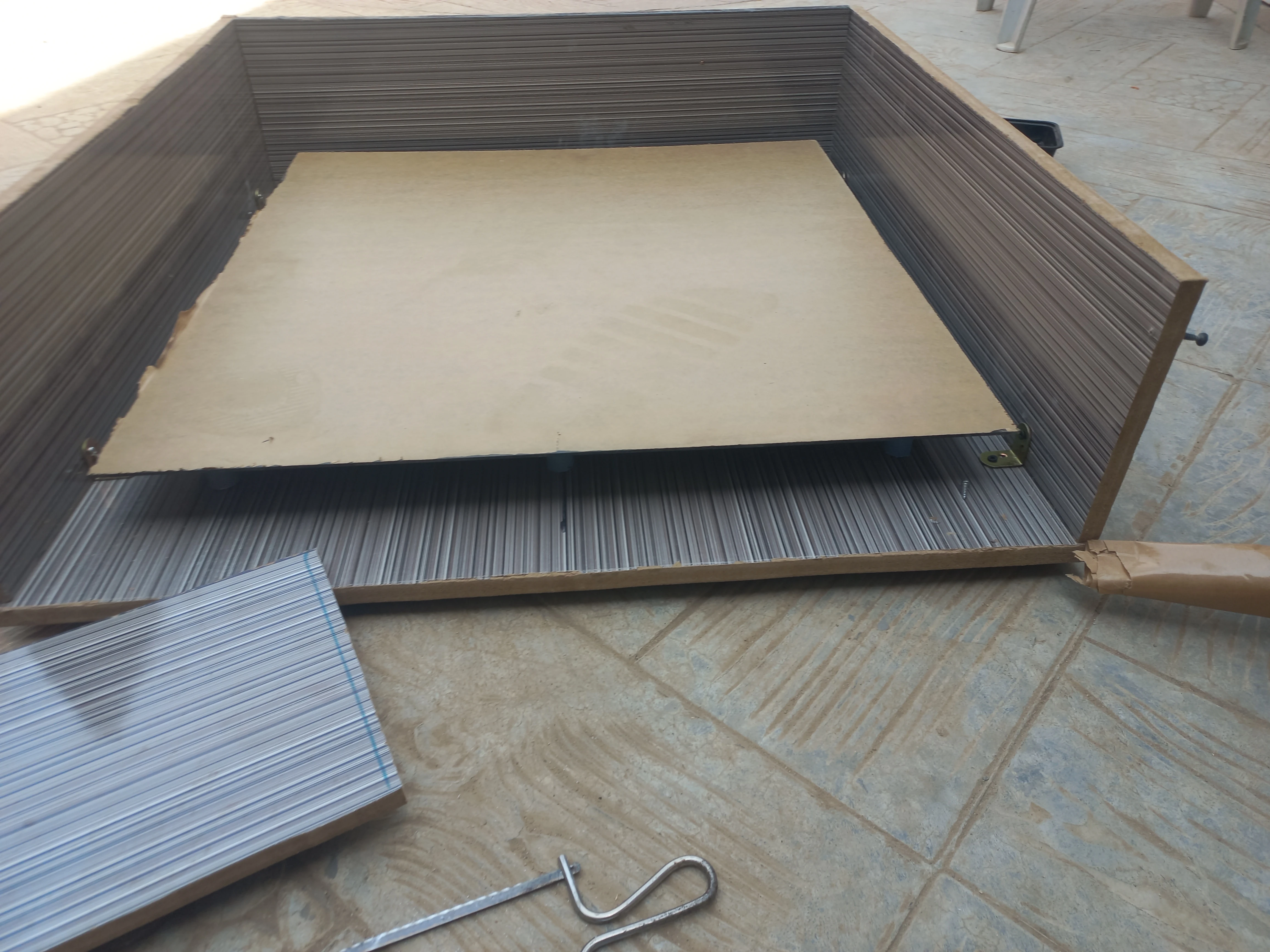
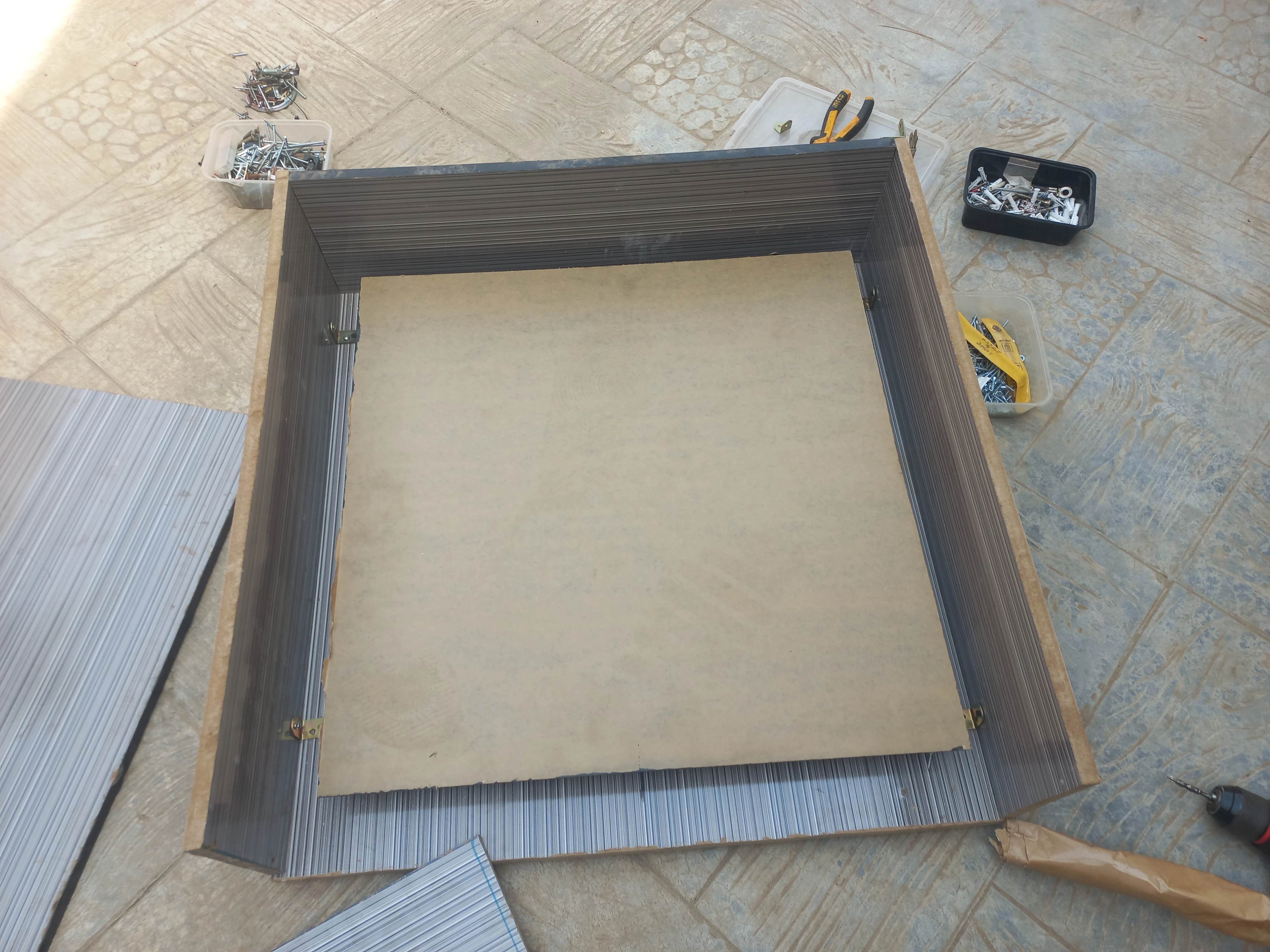
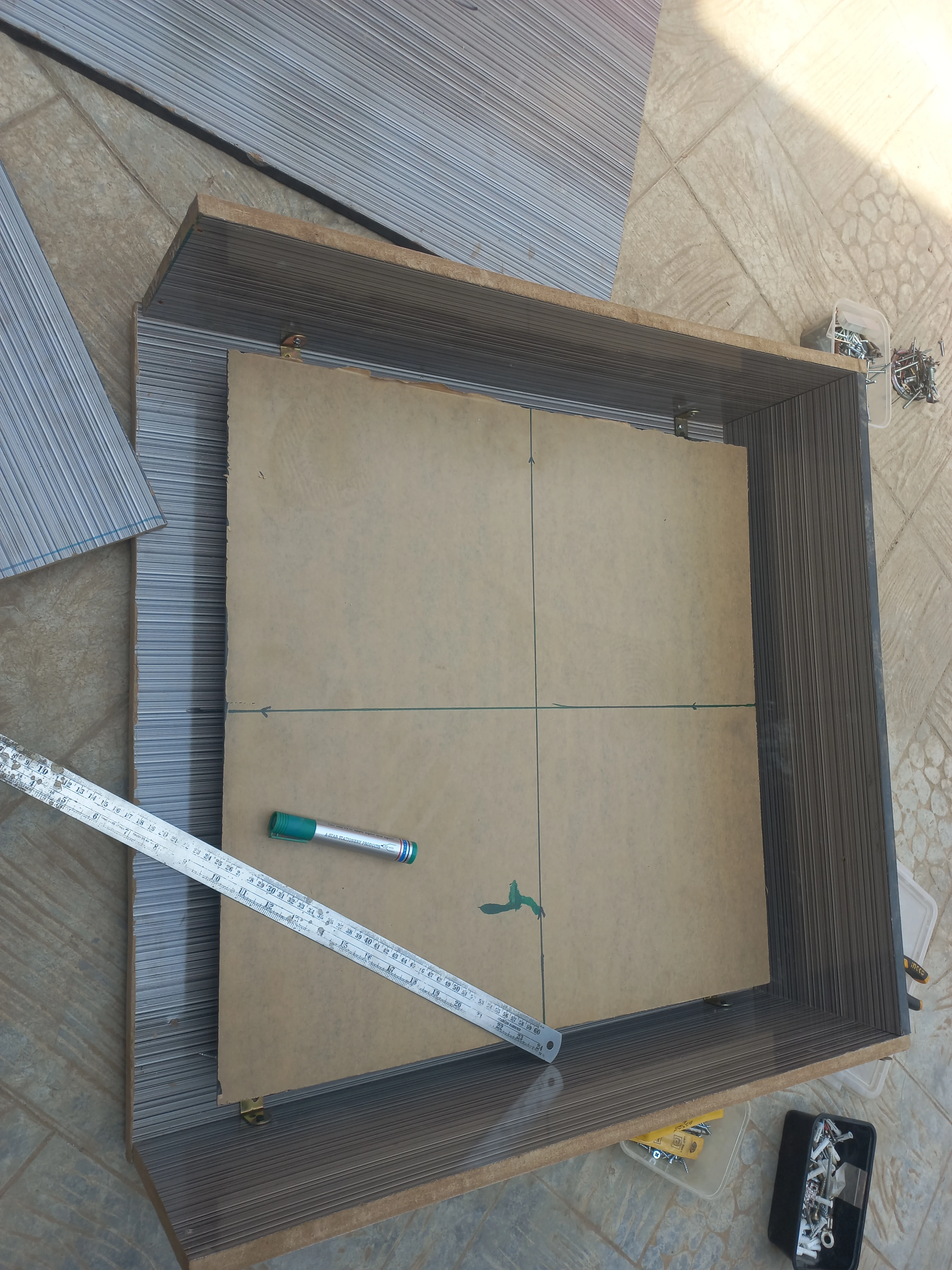
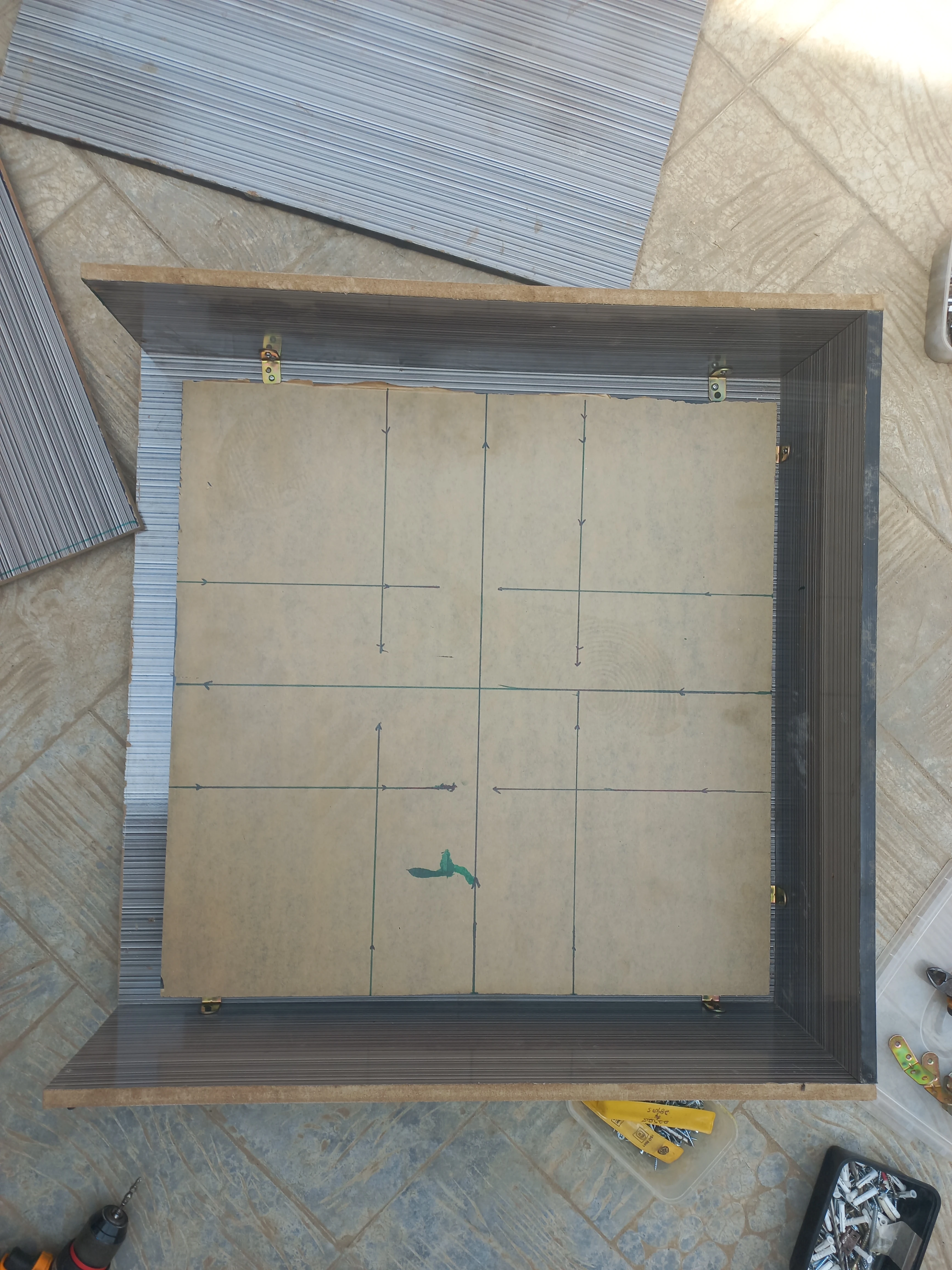
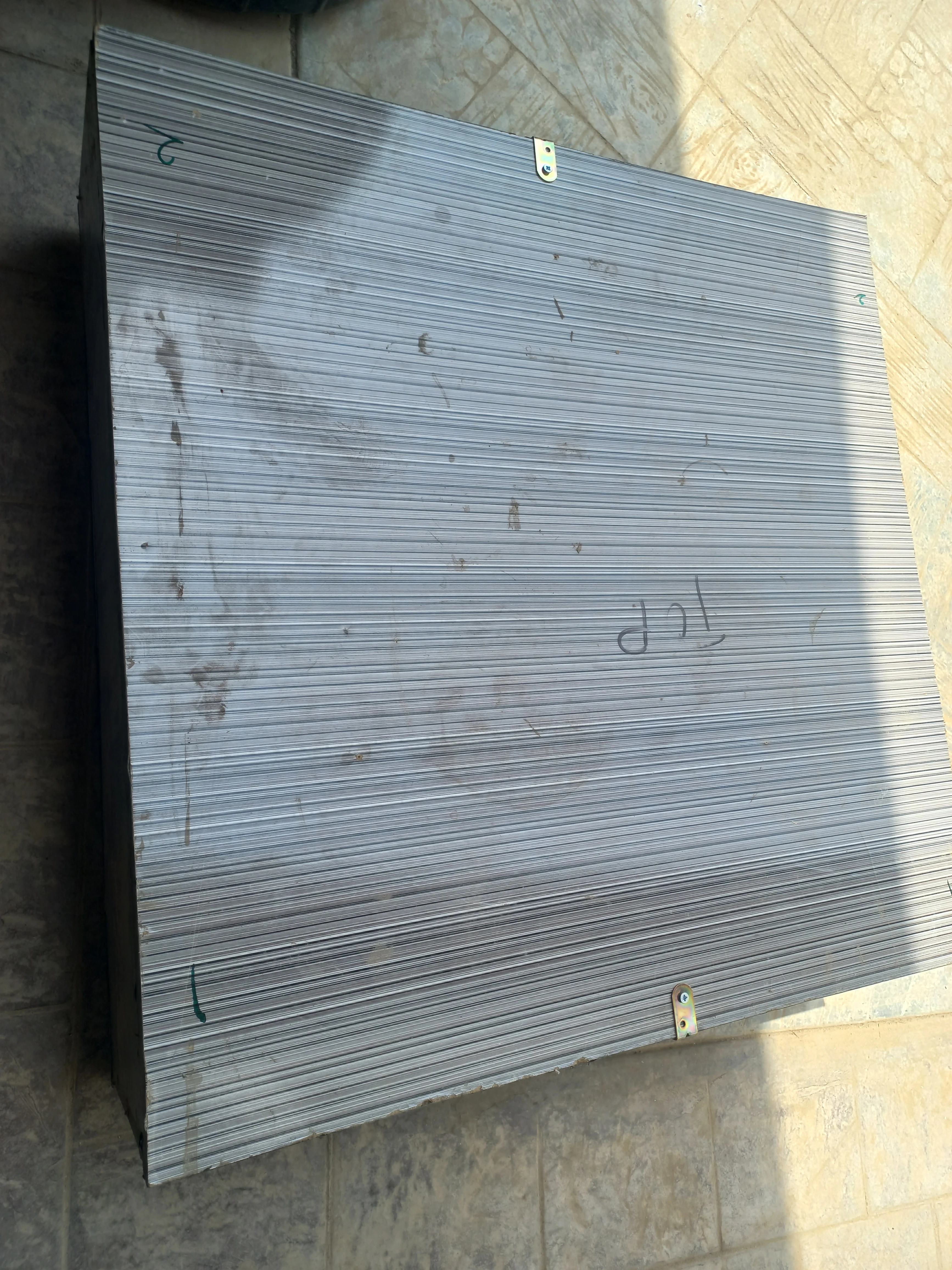
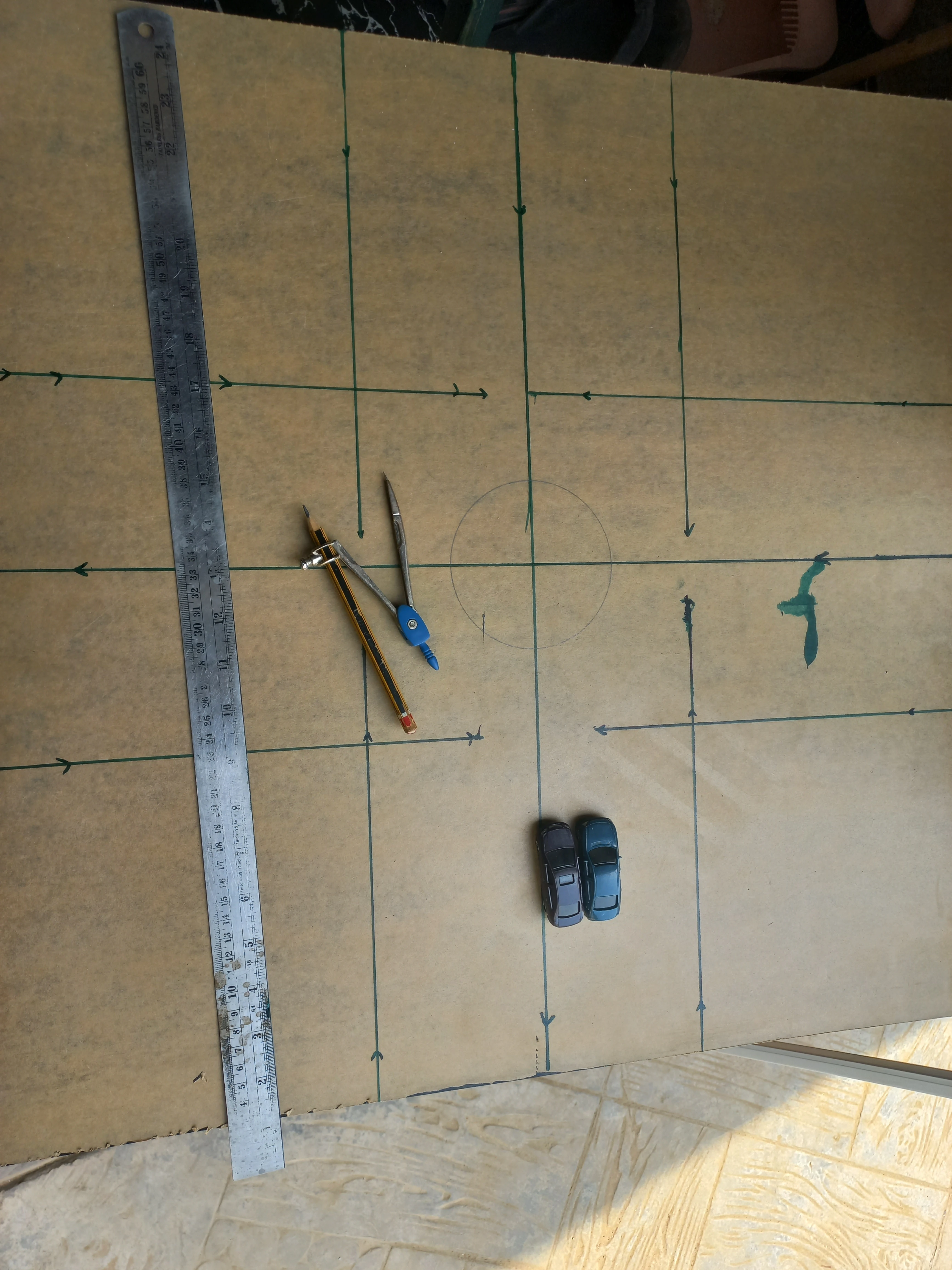
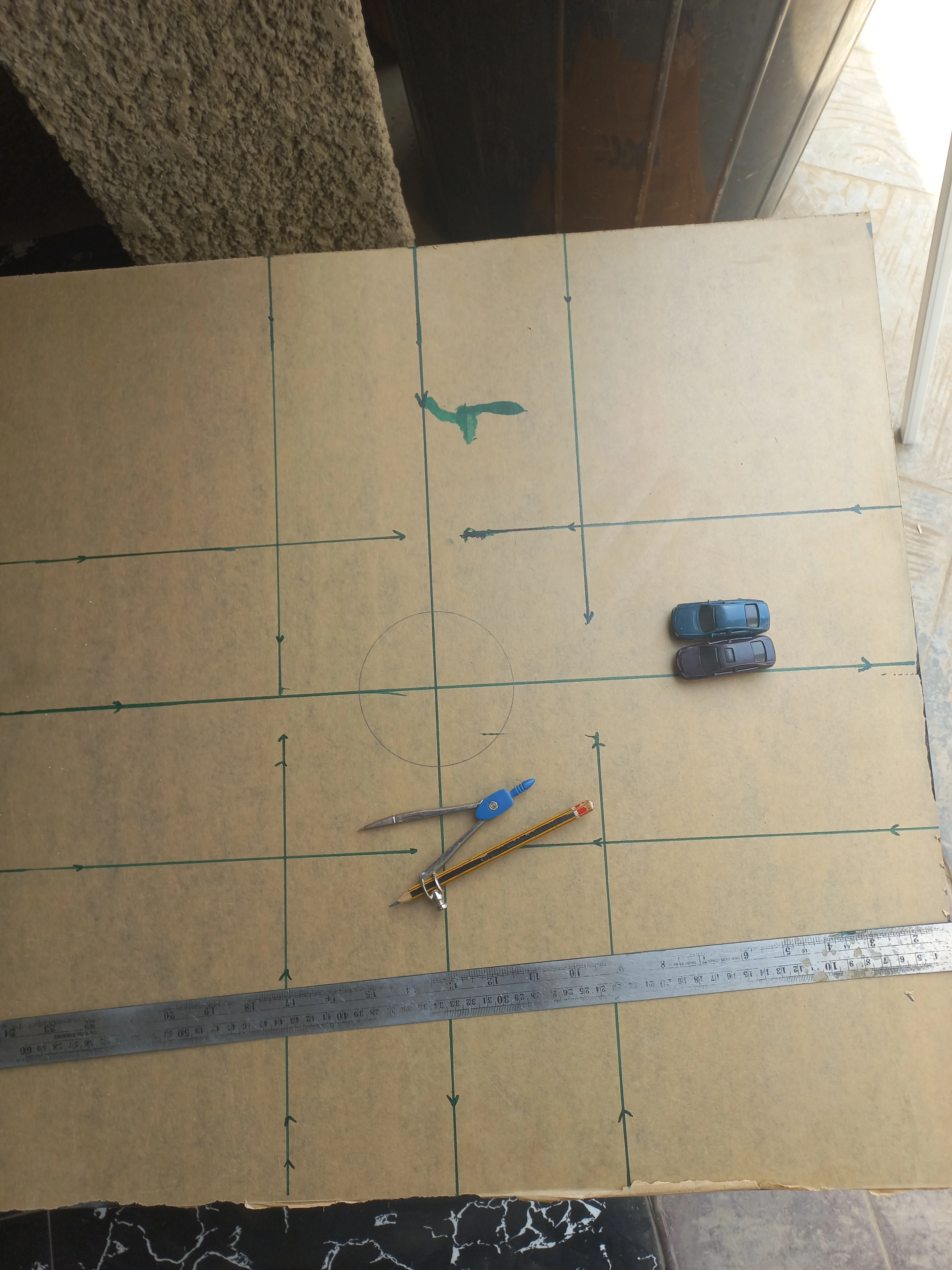
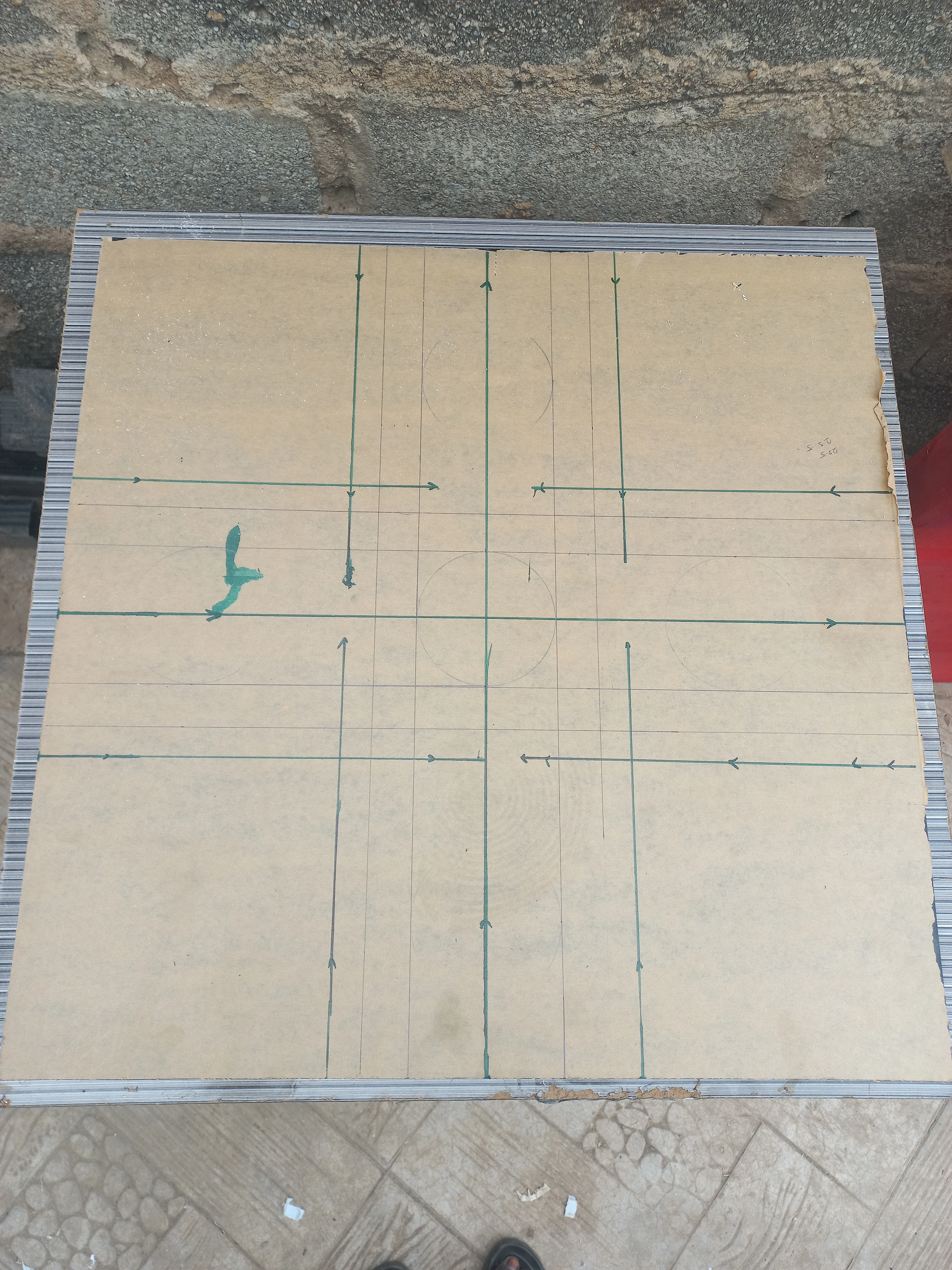
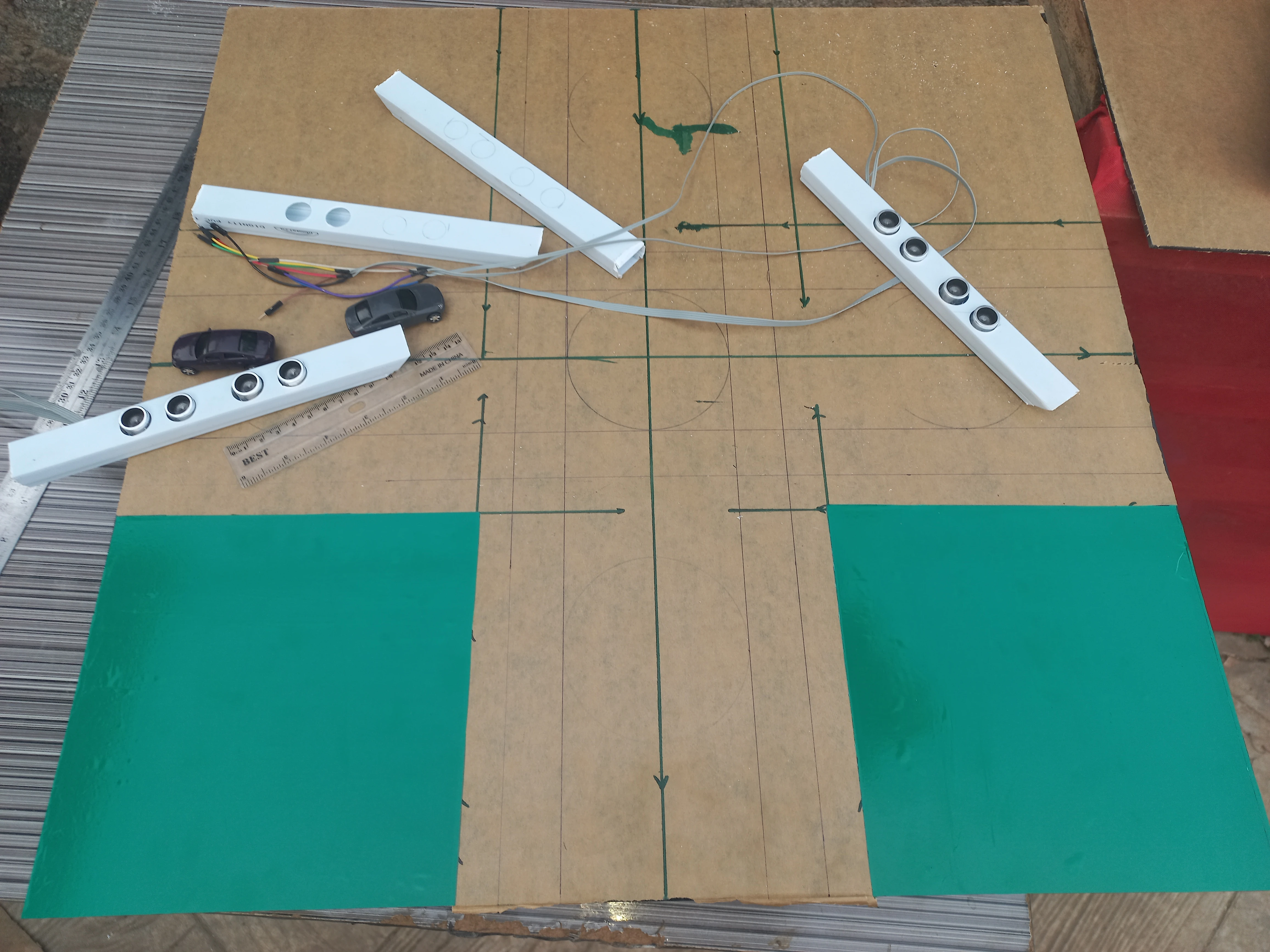
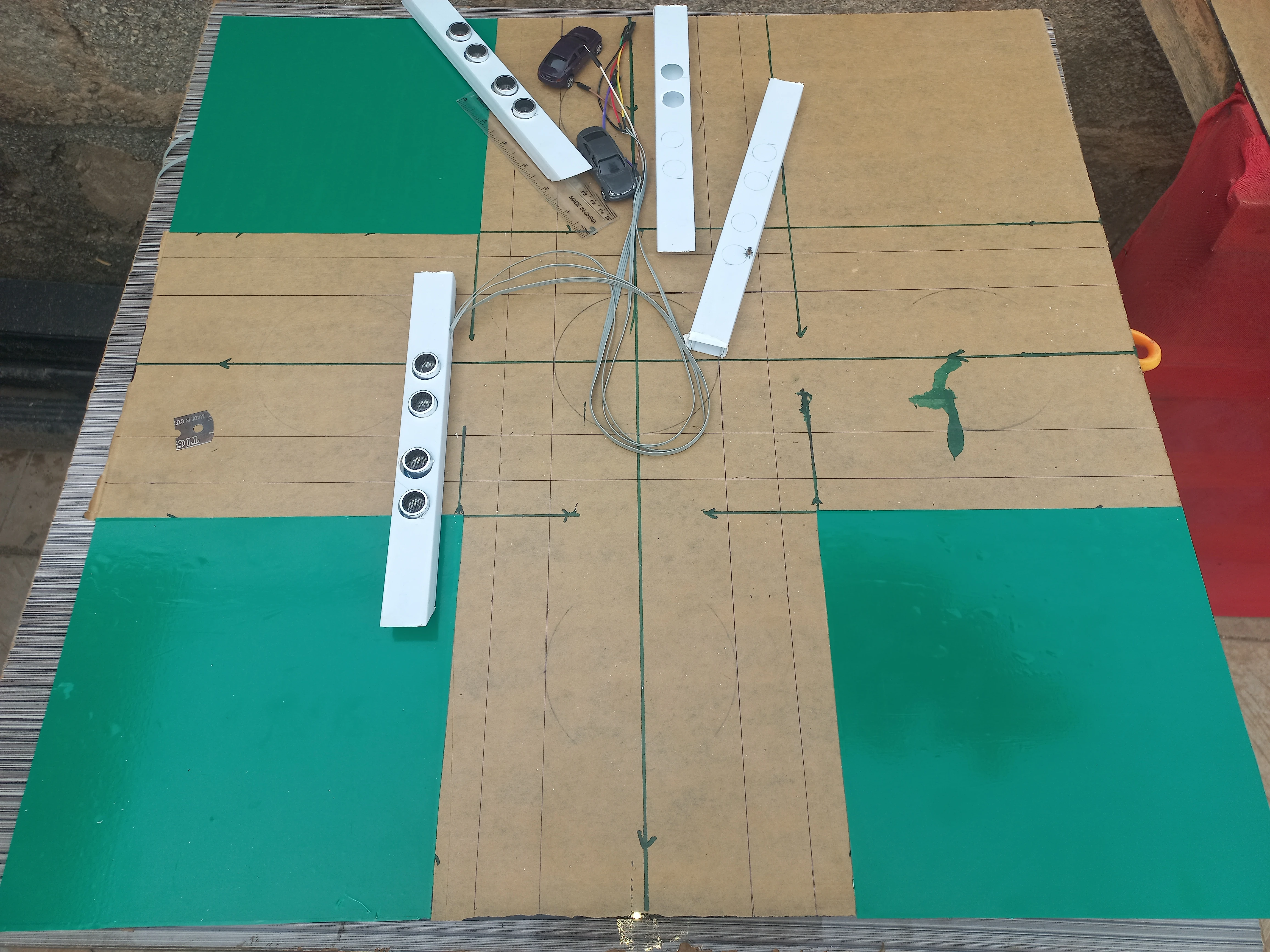
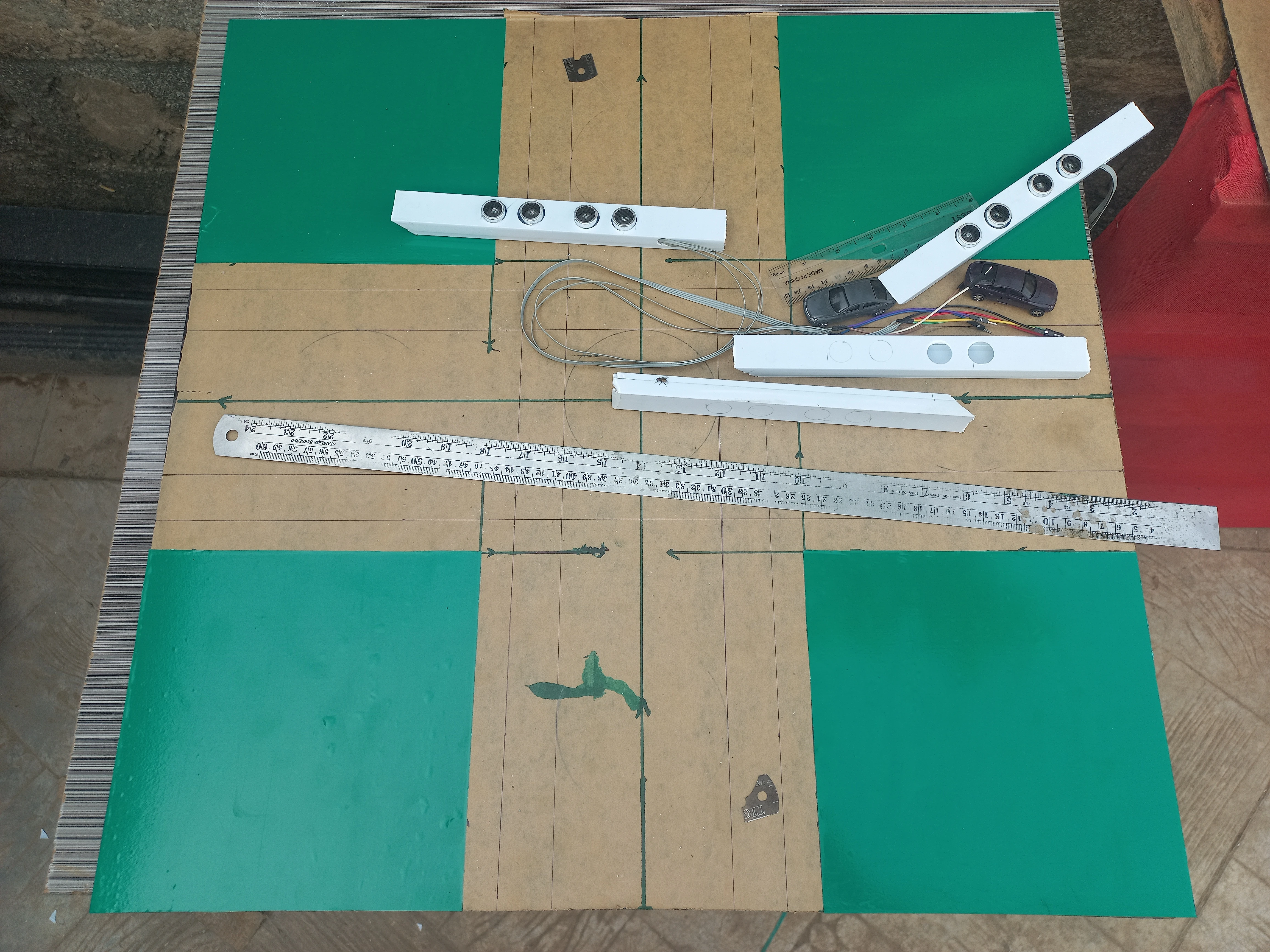
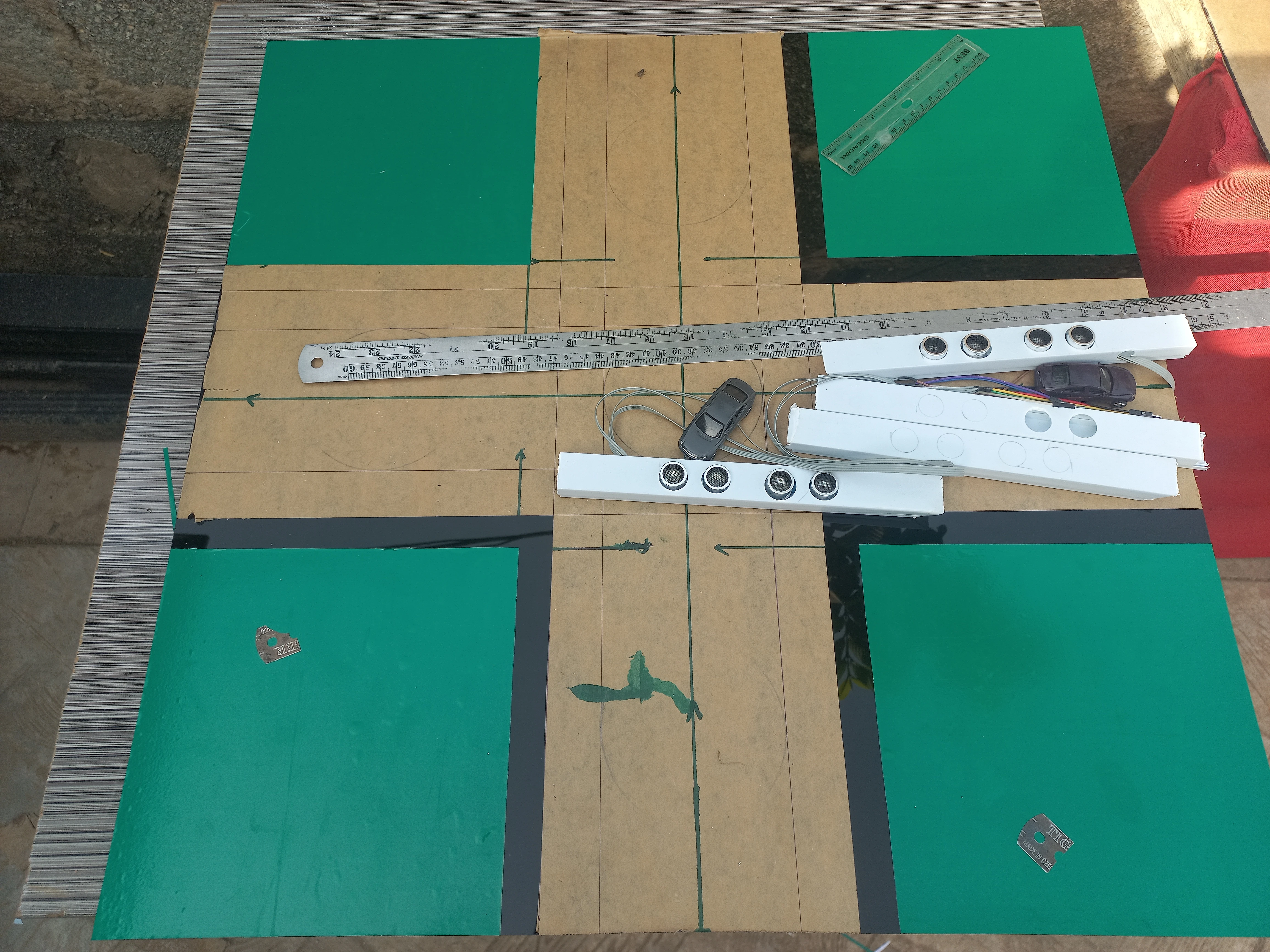
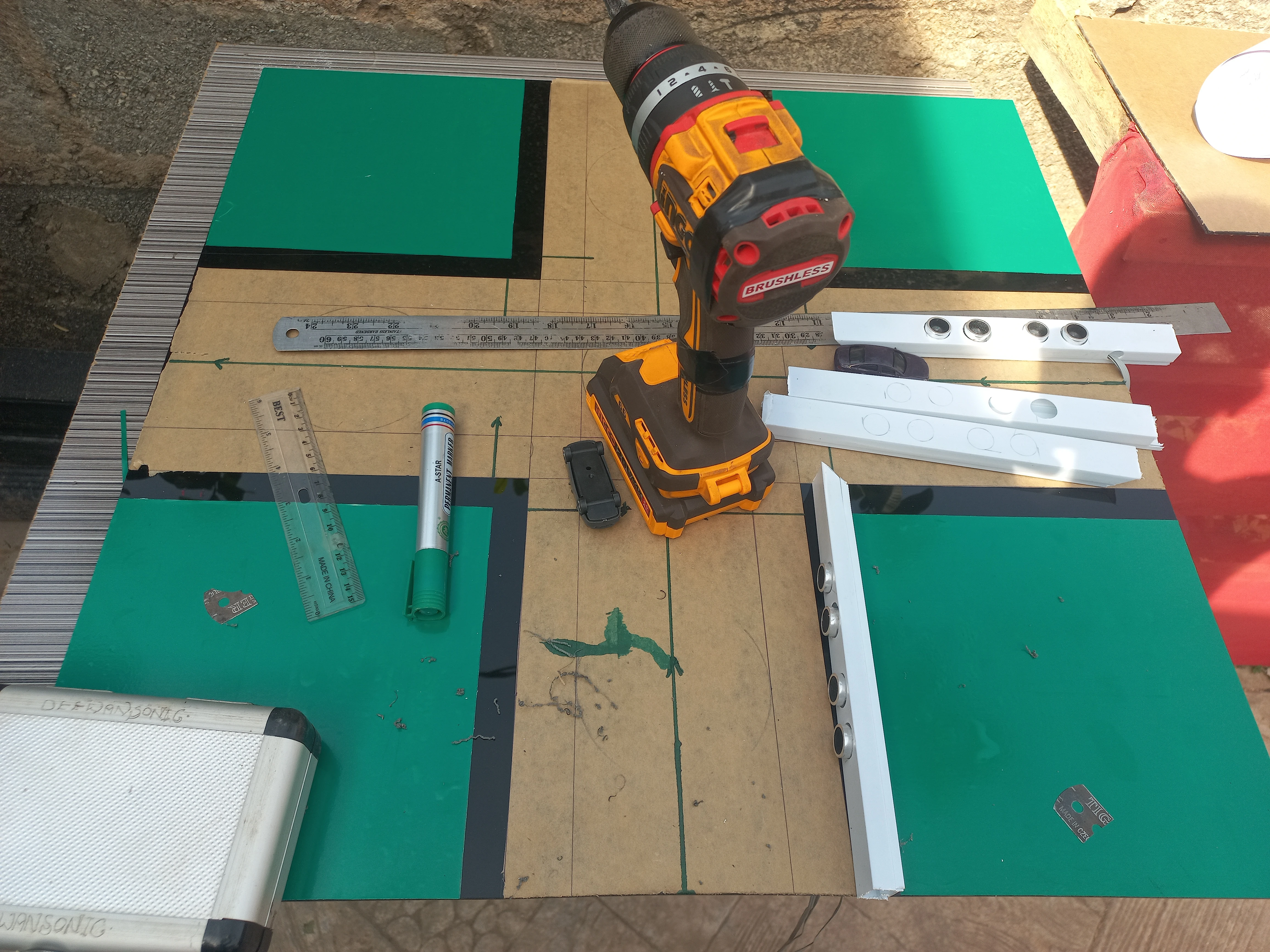
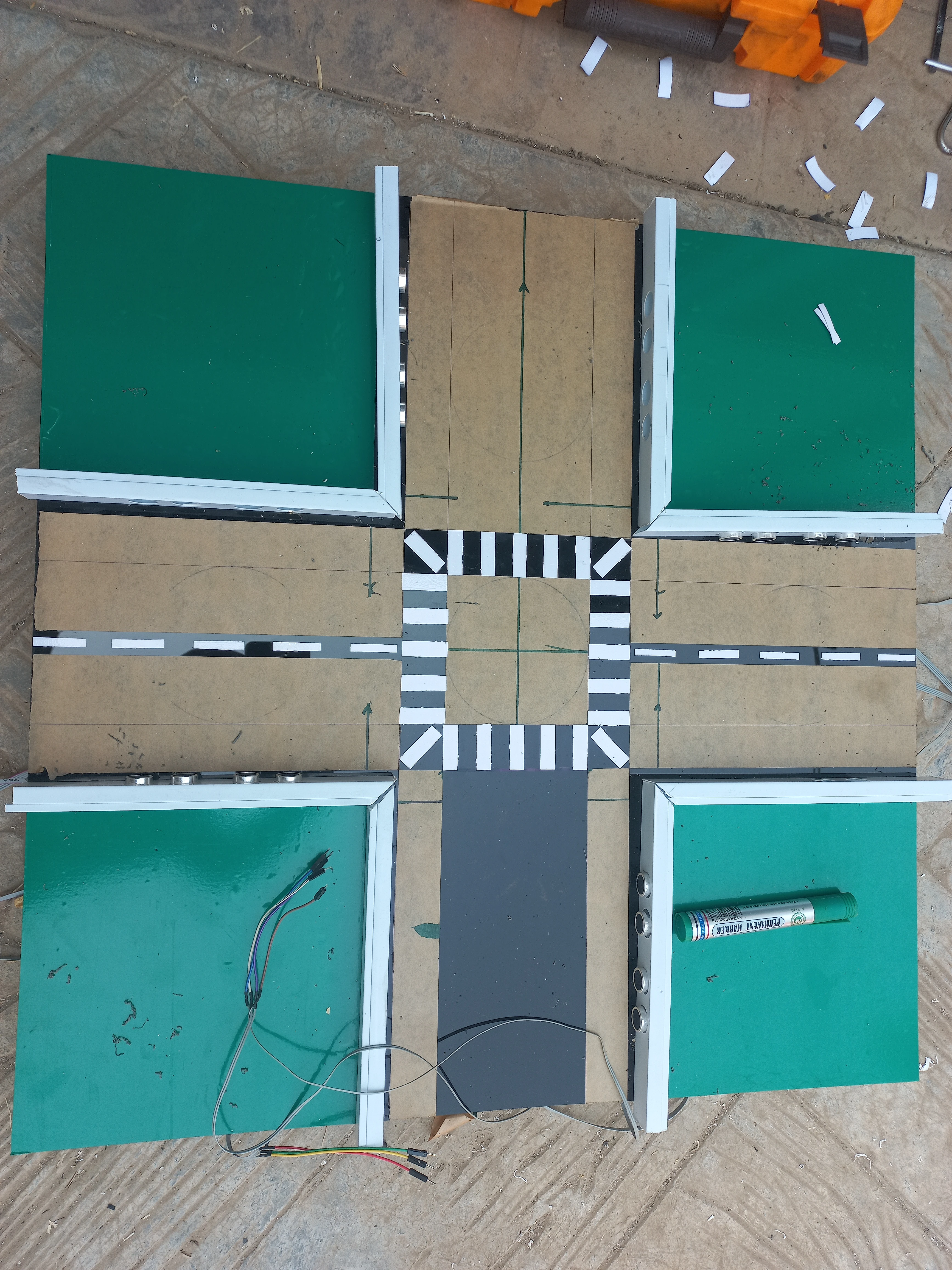
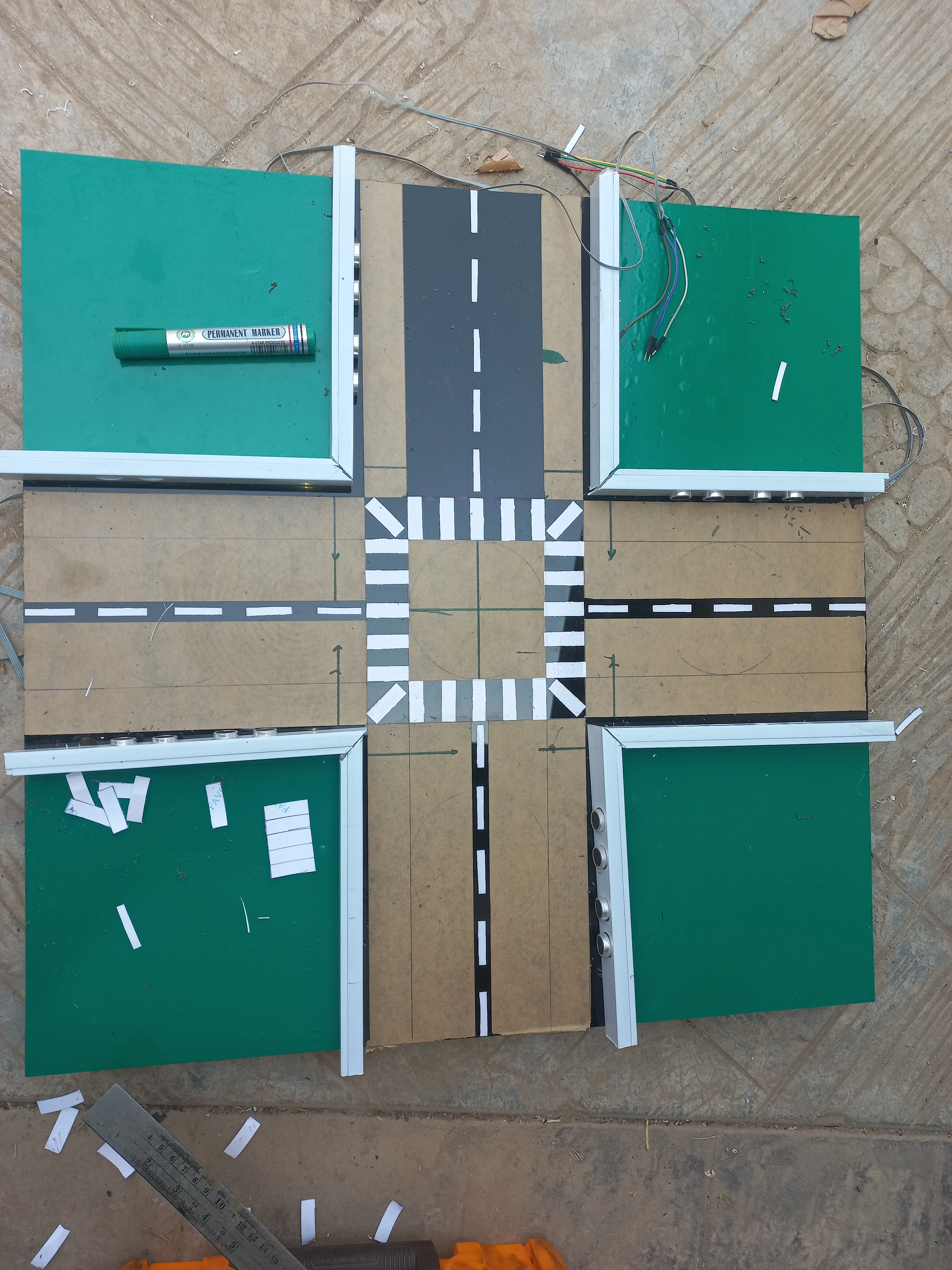
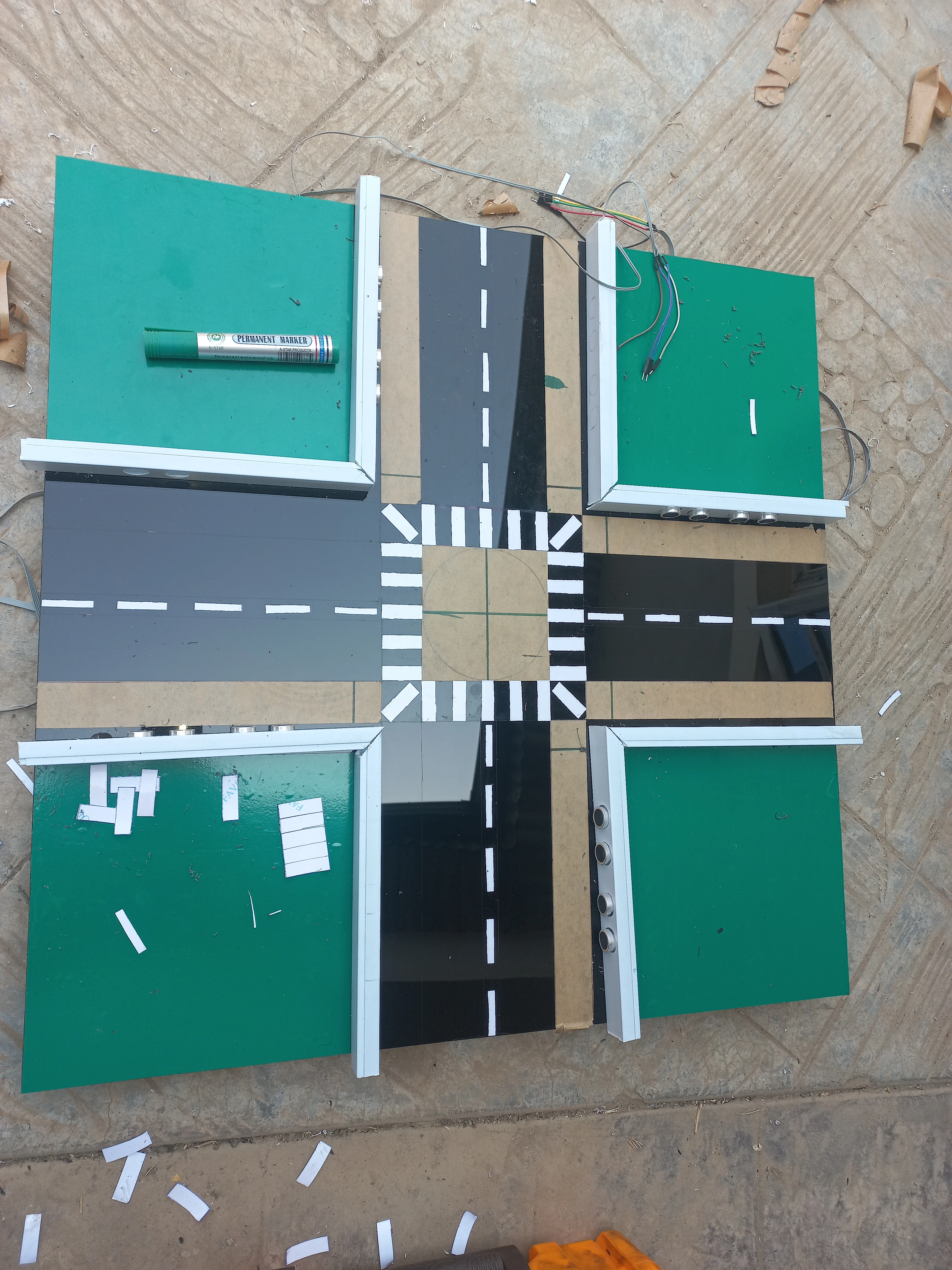
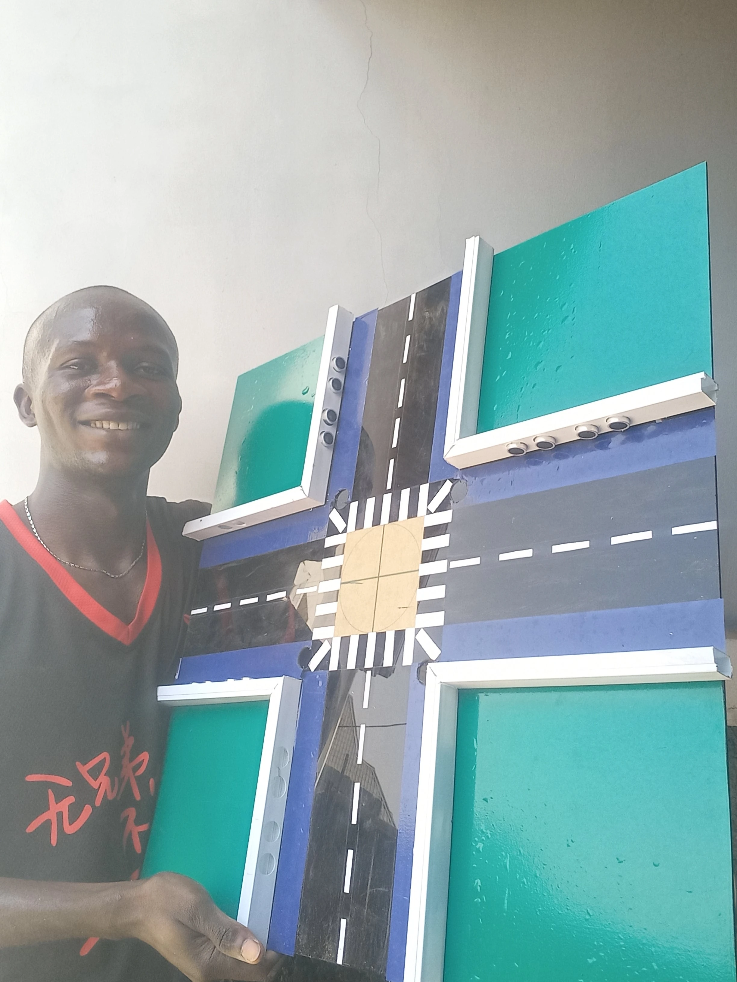
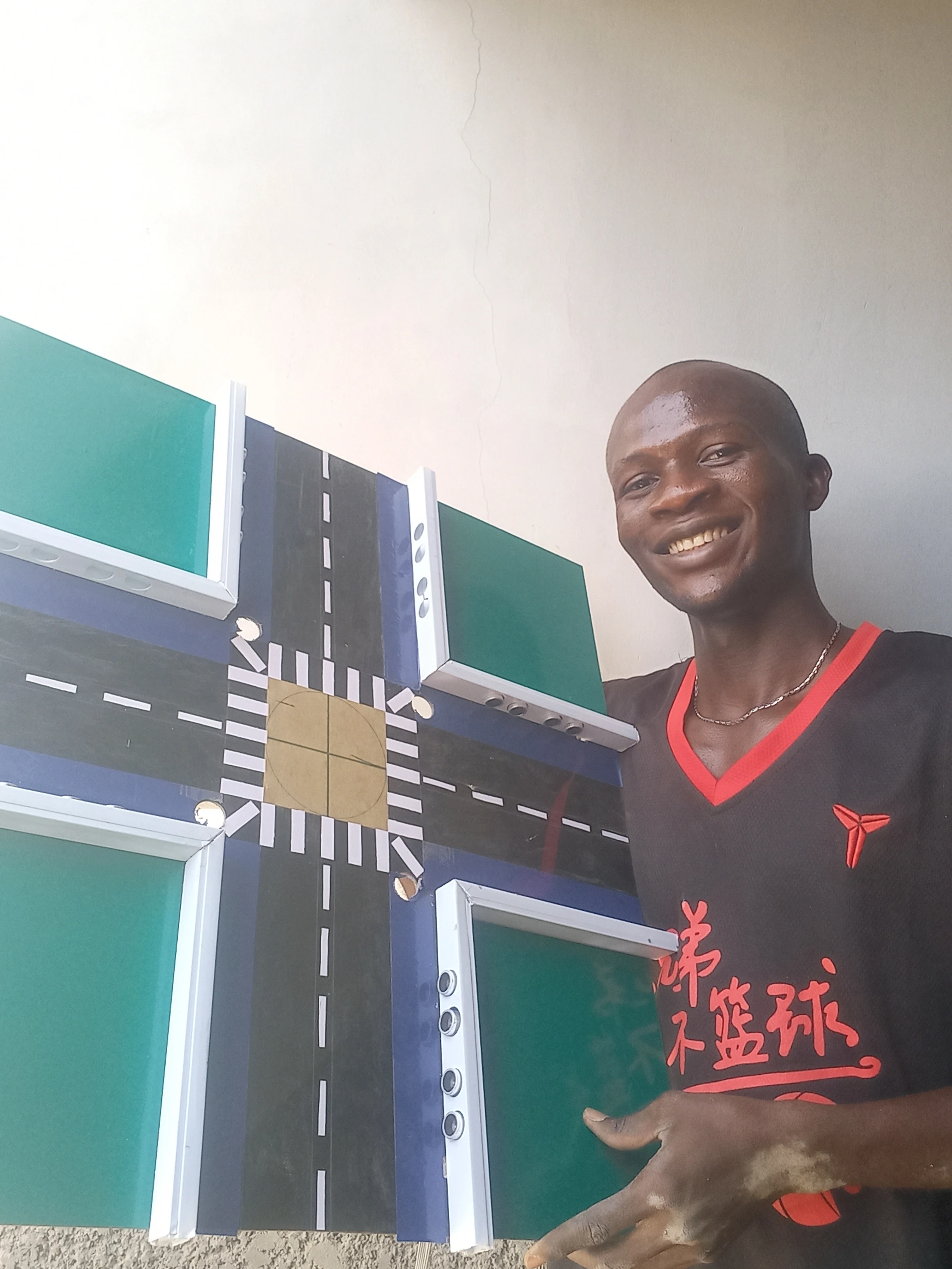
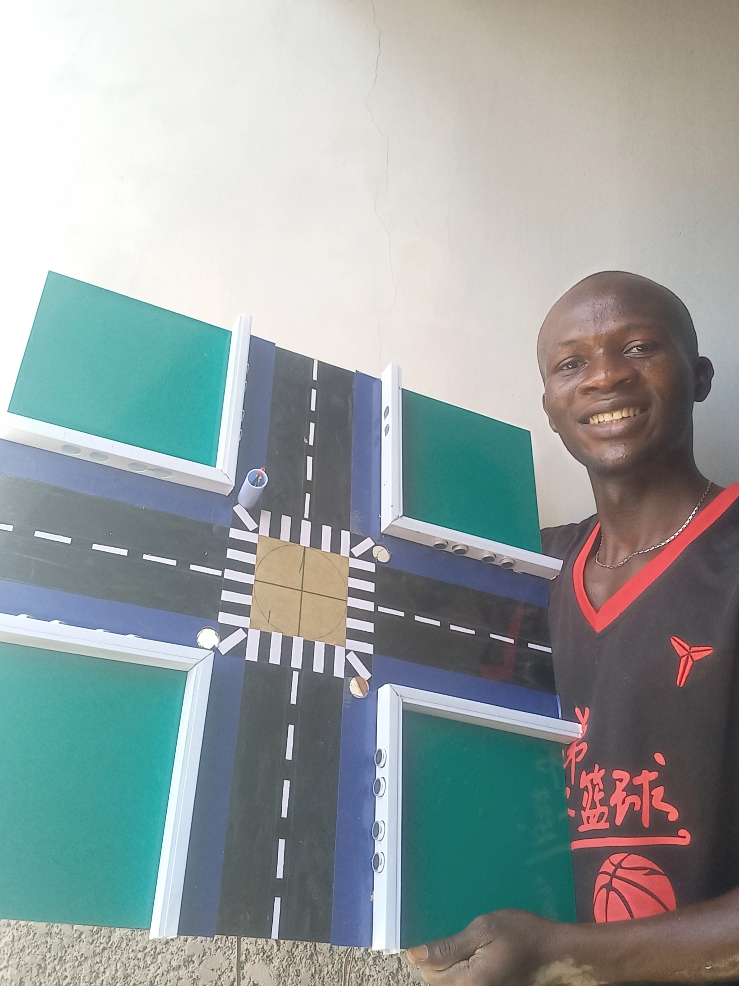
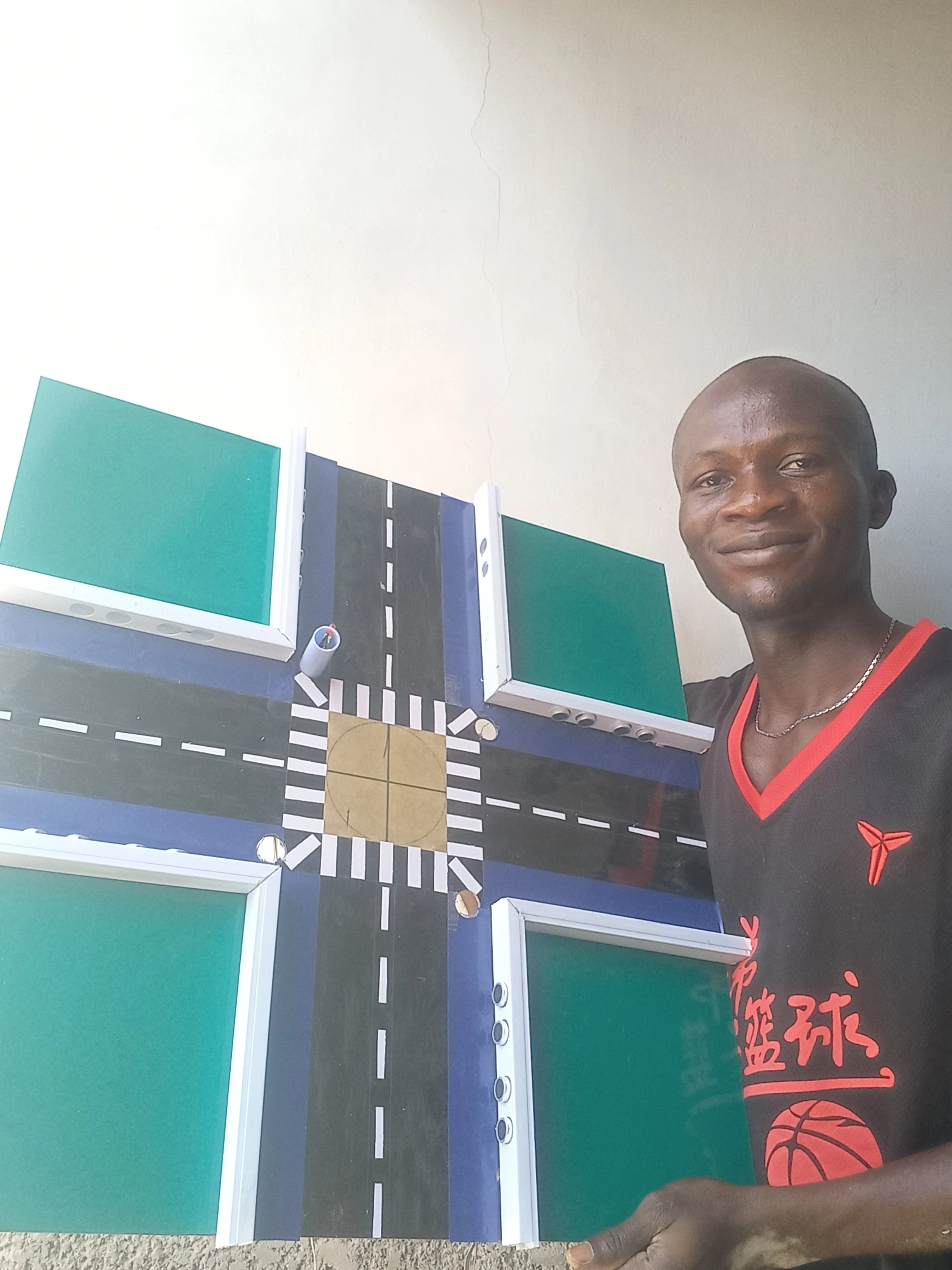
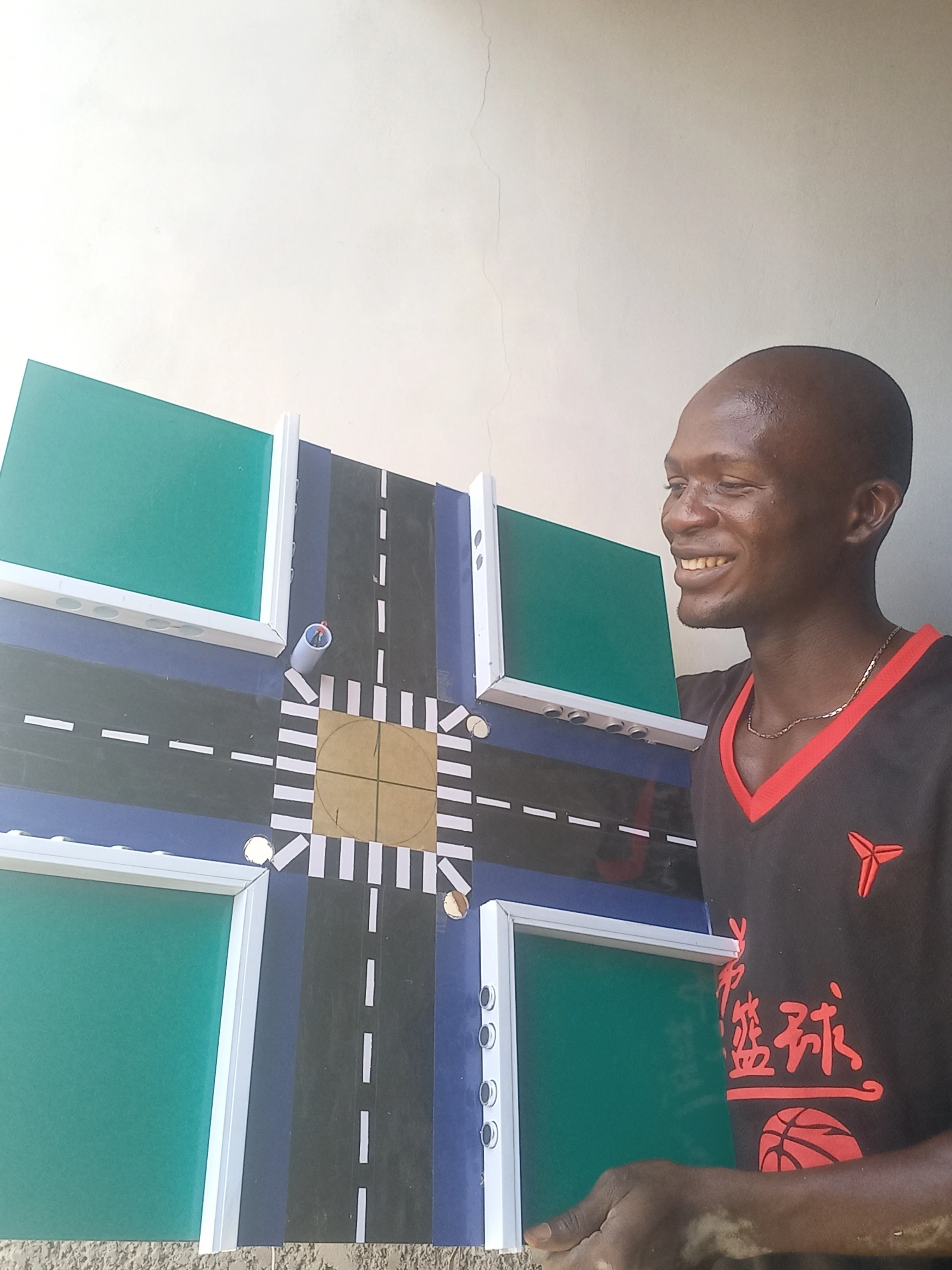
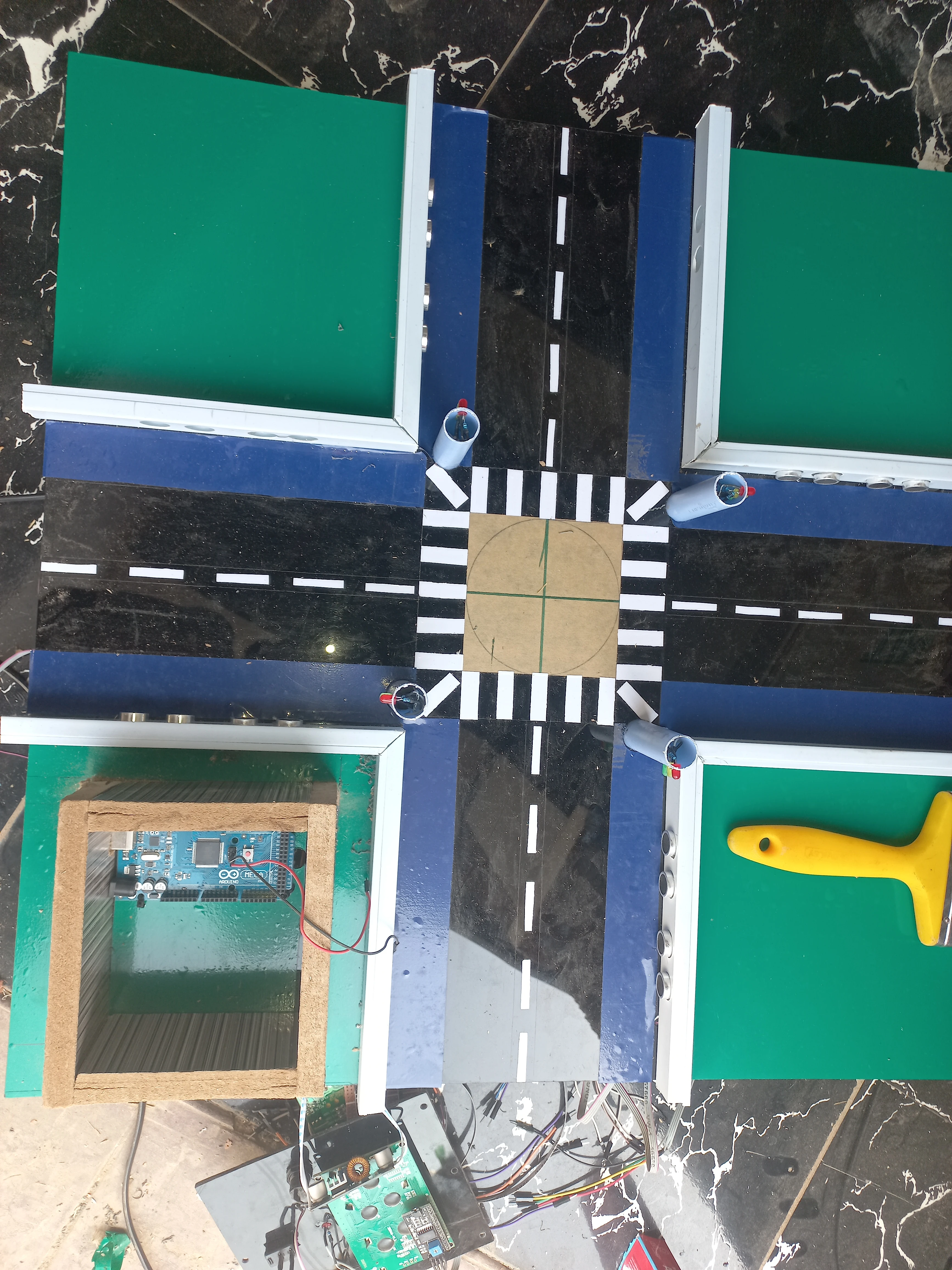
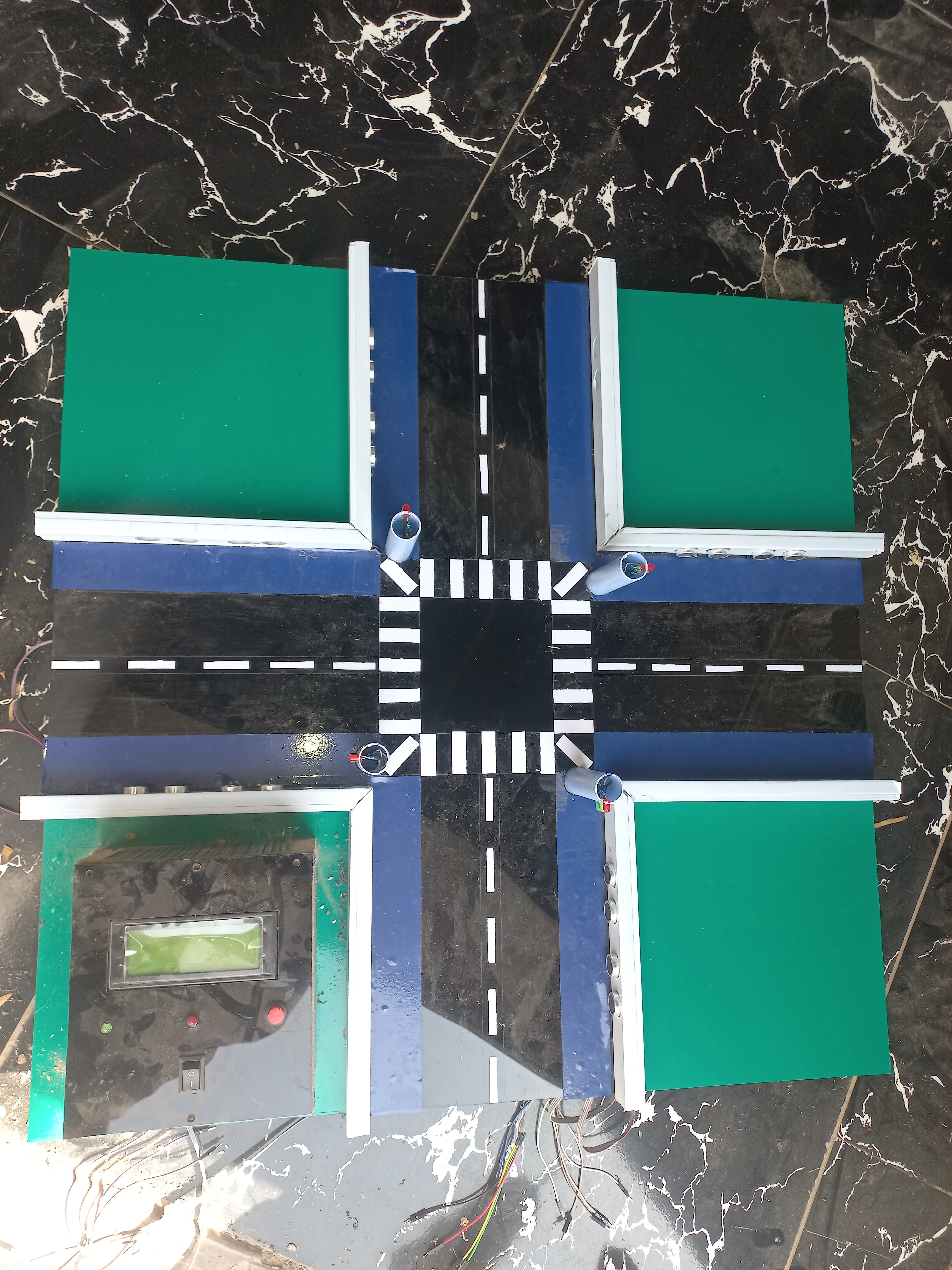
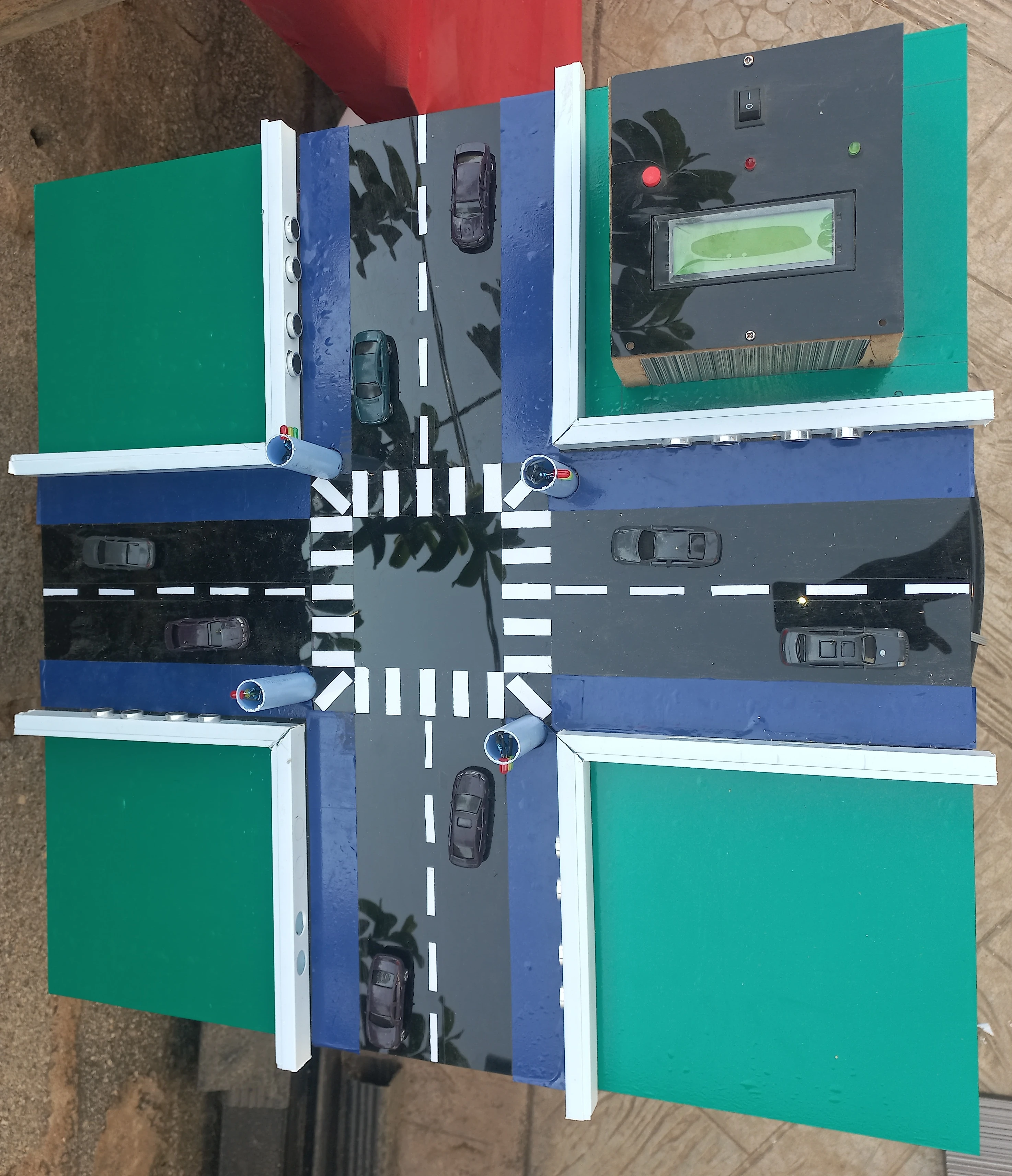
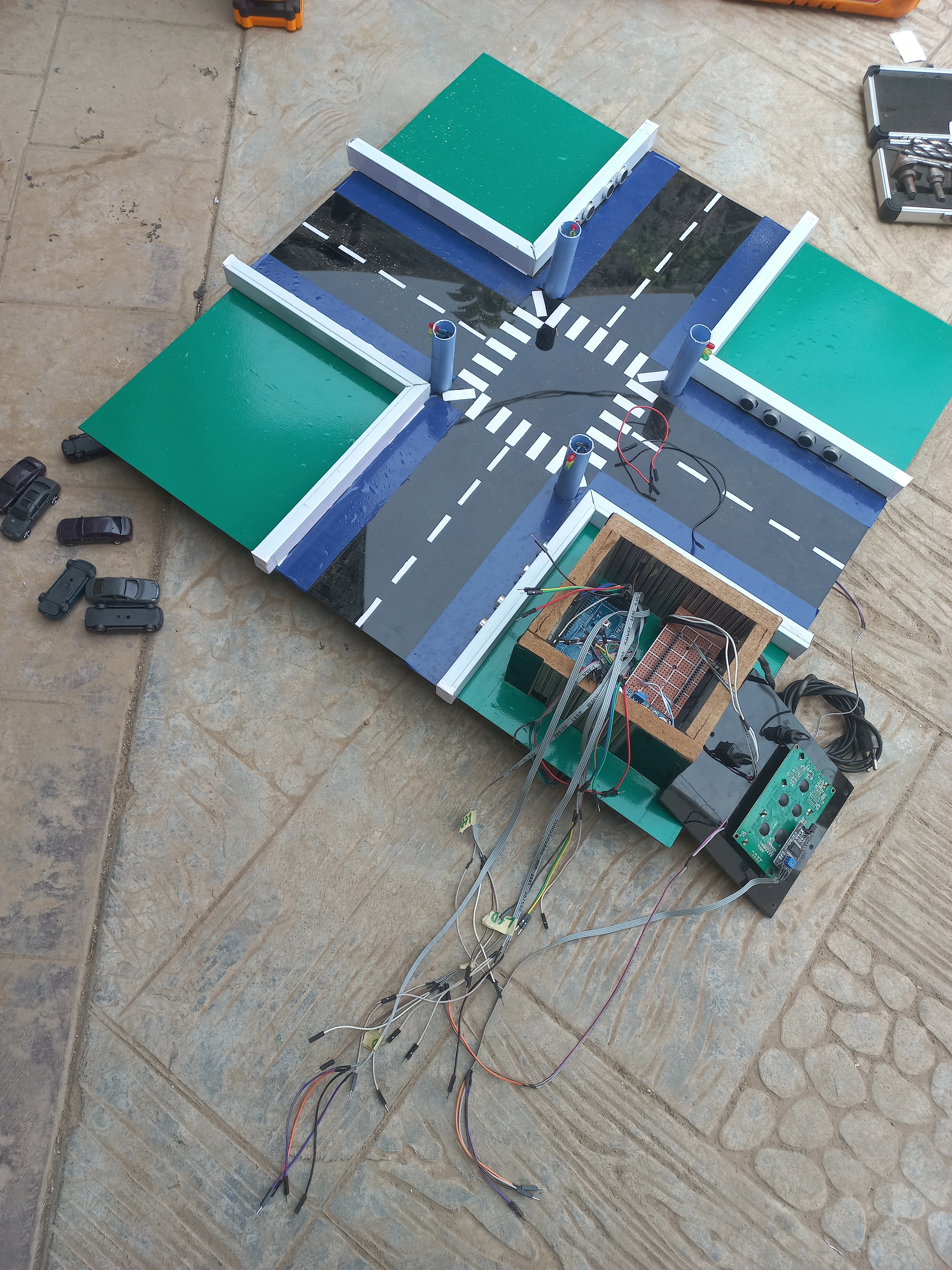
| Model Base | MDF board with WPC perimeter frame | Physical 4-lane cross-intersection simulation platform |
| Road Surface | Black acrylic + green acrylic verge panels | Represents tarmac road and grassed median strips |
| Enclosure | Composite board control box | Houses Arduino Mega, perfboard PSU, LCD, emergency button |
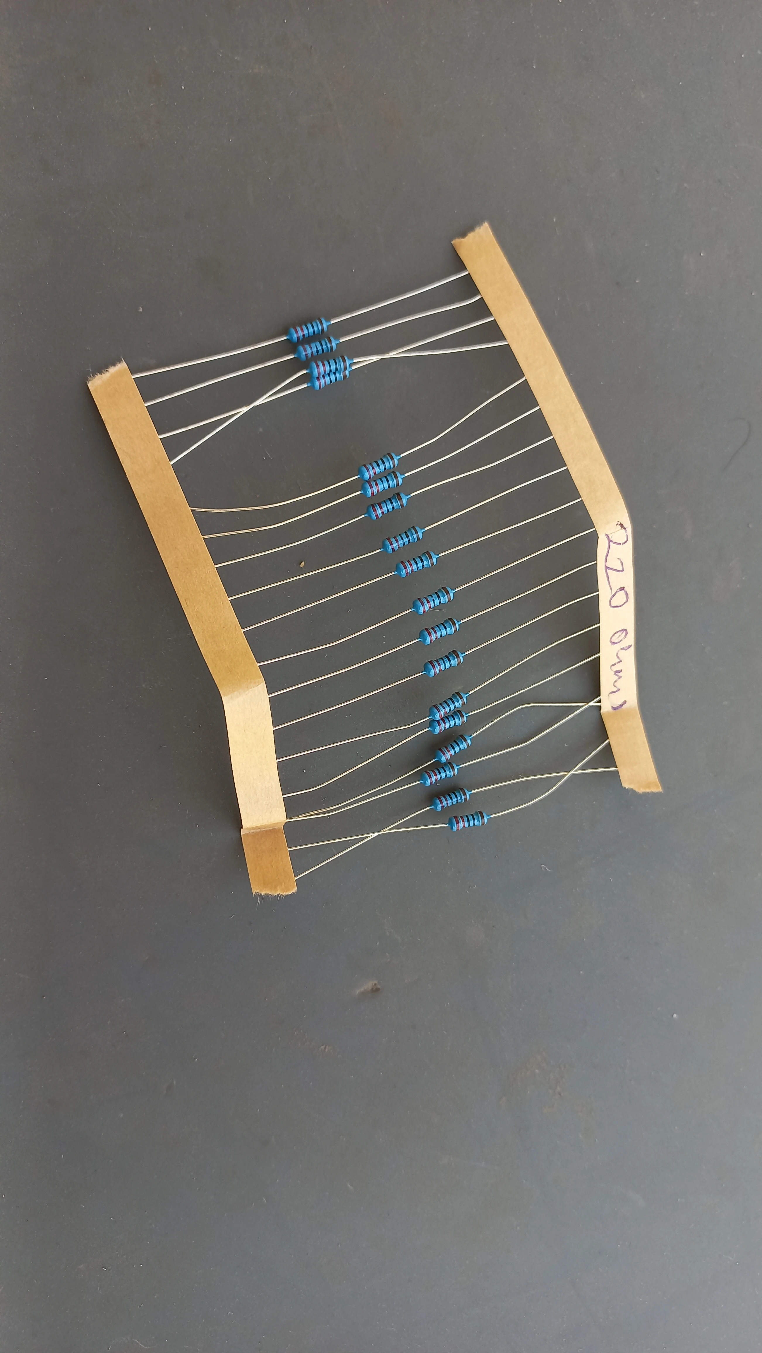
| Resistors | 220 Ω (12×) | Current-limiting for all traffic signal LEDs |
| Sensor | Lane / Position | Trig Pin | Echo Pin |
|---|---|---|---|
| L1_Sens1 | Lane 1 — Front (Axis 1) | 23 | 22 |
| L1_Sens2 | Lane 1 — Back (Axis 1) | 24 | 25 |
| L4_Sens1 | Lane 4 — Front (Axis 1) | 28 | 29 |
| L4_Sens2 | Lane 4 — Back (Axis 1) | 30 | 31 |
| L2_Sens1 | Lane 2 — Front (Axis 2) | 36 | 37 |
| L2_Sens2 | Lane 2 — Back (Axis 2) | 34 | 35 |
| L3_Sens1 | Lane 3 — Front (Axis 2) | 32 | 33 |
| L3_Sens2 | Lane 3 — Back (Axis 2) | 26 | 27 |
| Pin | Signal | Lane / Role |
|---|---|---|
| 9 | L1_R | Lane 1 (Top) — Red |
| 10 | L1_Y | Lane 1 (Top) — Yellow |
| 11 | L1_G | Lane 1 (Top) — Green |
| 16 | L4_R | Lane 4 (Bottom) — Red |
| 14 | L4_Y | Lane 4 (Bottom) — Yellow |
| 15 | L4_G | Lane 4 (Bottom) — Green |
| 6 | L2_R | Lane 2 (Left) — Red |
| 8 | L2_Y | Lane 2 (Left) — Yellow |
| 7 | L2_G | Lane 2 (Left) — Green |
| 3 | L3_R | Lane 3 (Right) — Red |
| 4 | L3_Y | Lane 3 (Right) — Yellow |
| 5 | L3_G | Lane 3 (Right) — Green |
| 12 | buttonPin | Emergency override push button (INPUT_PULLUP) |
| 13 | consoleLED | Status LED — solid in auto mode, 200 ms flash in emergency |
| SDA/SCL | I2C | 20×4 LCD via PCF8574 backpack (address 0x27) |
if (frontCm < 0) frontCm = 999; — negative readings are clamped to 999 cm, which always evaluates to EMPTY, preventing spurious CROWDED triggers from sensor noise.
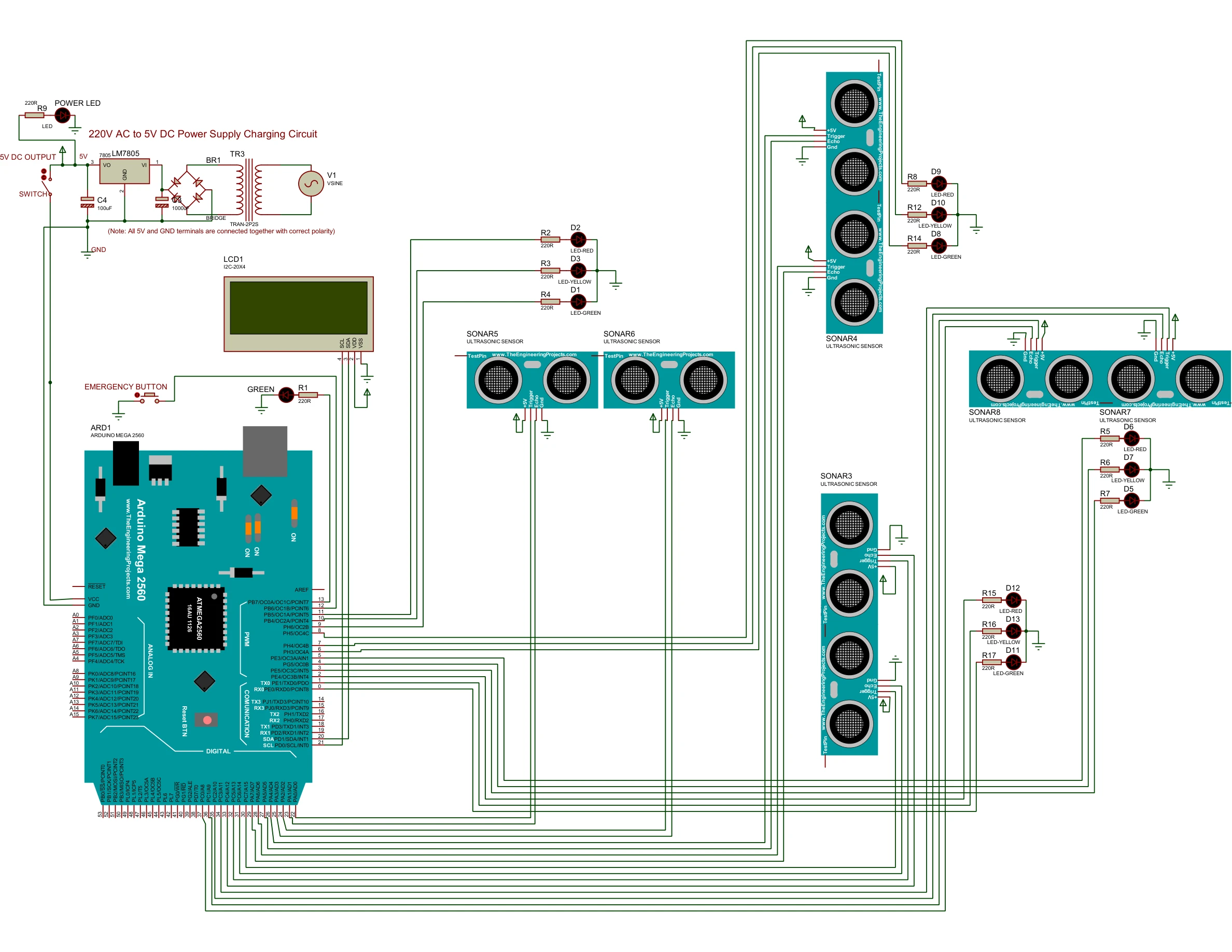
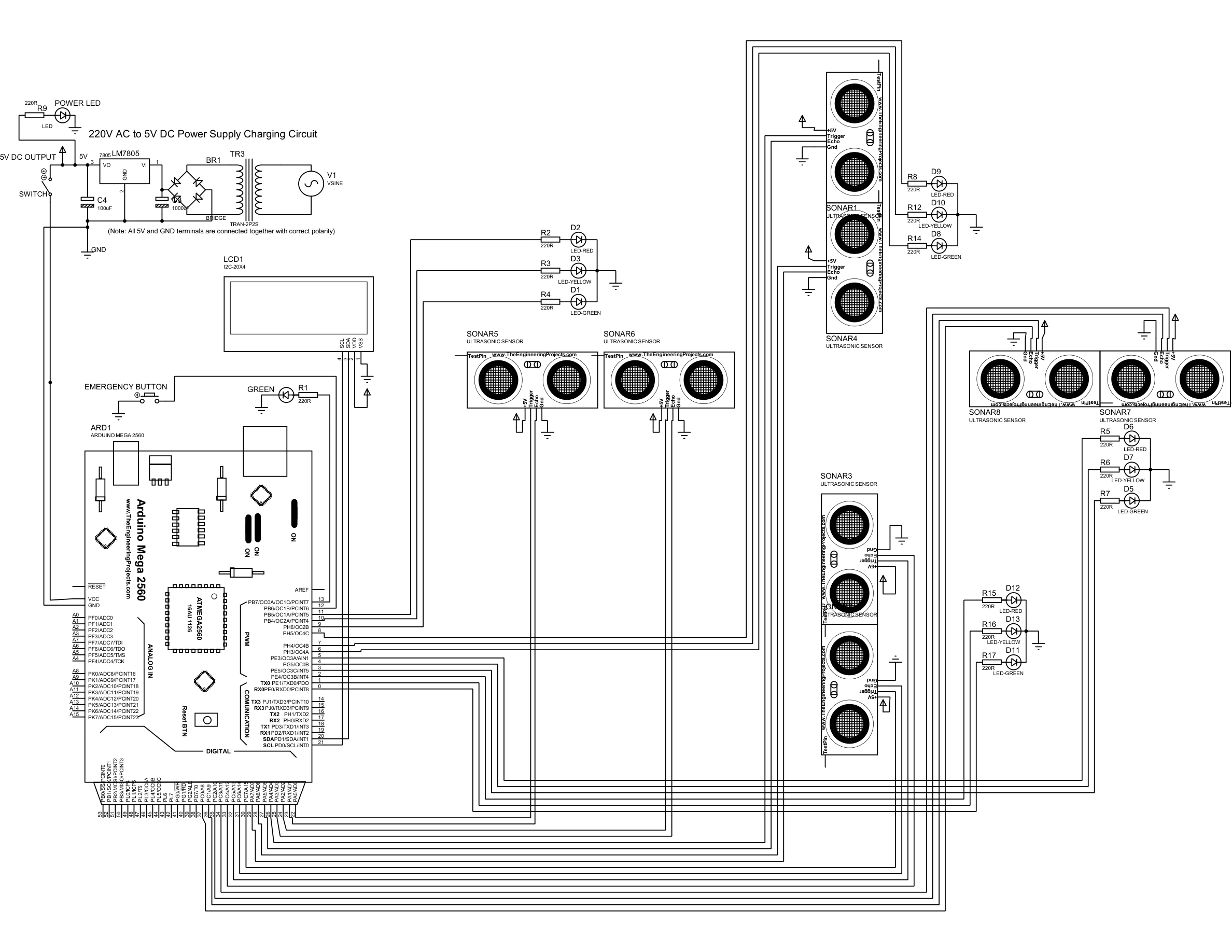
Both diagrams were produced in Proteus Design Suite and show the full 4-lane intersection wiring: Arduino Mega 2560, 8 HC-SR04 sensors in 4 front-back pairs, 12 traffic LEDs with 220 Ω current-limiting resistors, 20×4 I2C LCD, emergency push button, and the 12 V PSU with buck converter regulated 5 V rail.
The controller cycles through six states in a fixed sequence. Axis 1 (Lanes 1 & 4, top and bottom) and Axis 2 (Lanes 2 & 3, left and right) alternate green phases separated by mandatory 5 s yellow transitions. Both GREEN states include a Smart Interrupt check on every loop tick.
currentDuration to 30 s (CROWDED), 15 s (NORMAL), or 30 s (EMPTY oscillate). Calls triggerAxis1Green() and advances immediately.currentDuration = 0. Transitions to AXIS1_YELLOW when elapsed ≥ duration.TIME_YELLOW (5 s), then advances to AXIS2_EVAL. Axis 2 remains red throughout.triggerAxis2Green() — which calls setAllRed() first for safety — and advances immediately.triggerAxis_Green() call begins with setAllRed(), ensuring all twelve LEDs are explicitly placed in the correct state before the new green axis is activated. There is no assumption about prior pin state.
Written in Arduino C++ (Arduino IDE) using the HCSR04 library for sensor abstraction and LiquidCrystal_I2C for LCD control. Three key excerpts are shown below.
// Returns EMPTY, NORMAL, or CROWDED based on front and back sensor readings.
// Negative readings (no echo) are clamped to 999 cm = EMPTY.
Density getLaneDensity(float frontCm, float backCm) {
  if (frontCm < 0) frontCm = 999;
  if (backCm  < 0) backCm  = 999;

  if (frontCm < 12.0 && backCm < 12.0) return CROWDED;
  if (frontCm < 12.0 || backCm < 12.0) return NORMAL;
  return EMPTY;
}

void scanAllLanes() {
  Density L1 = getLaneDensity(L1_Sens1.measureDistanceCm(), L1_Sens2.measureDistanceCm());
  Density L4 = getLaneDensity(L4_Sens1.measureDistanceCm(), L4_Sens2.measureDistanceCm());
  axis1Status = max(L1, L4);  // worst-case axis density

  Density L2 = getLaneDensity(L2_Sens1.measureDistanceCm(), L2_Sens2.measureDistanceCm());
  Density L3 = getLaneDensity(L3_Sens1.measureDistanceCm(), L3_Sens2.measureDistanceCm());
  axis2Status = max(L2, L3);
}void manageTrafficLogic() {
unsigned long elapsed = millis() - stateStartTime;
switch (currentState) {
case AXIS1_EVAL:
activeAxisStr = "1 & 4 (MAIN)";
currentDuration = (axis1Status == CROWDED) ? TIME_CROWDED
: (axis1Status == NORMAL) ? TIME_NORMAL
: TIME_EMPTY_OSCILLATE;
triggerAxis1Green();
currentState = AXIS1_GREEN;
break;
case AXIS1_GREEN:
// Smart Interrupt: skip idle green if opposing axis has vehicles
if (axis1Status == EMPTY && axis2Status > EMPTY) { currentDuration = 0; }
if (elapsed >= currentDuration) { triggerAxis1Yellow(); currentState = AXIS1_YELLOW; }
break;
case AXIS1_YELLOW:
if (elapsed >= TIME_YELLOW) { currentState = AXIS2_EVAL; }
break;
case AXIS2_EVAL:
activeAxisStr = "2 & 3 (SIDE)";
currentDuration = (axis2Status == CROWDED) ? TIME_CROWDED
: (axis2Status == NORMAL) ? TIME_NORMAL
: TIME_EMPTY_OSCILLATE;
triggerAxis2Green();
currentState = AXIS2_GREEN;
break;
case AXIS2_GREEN:
if (axis2Status == EMPTY && axis1Status > EMPTY) { currentDuration = 0; }
if (elapsed >= currentDuration) { triggerAxis2Yellow(); currentState = AXIS2_YELLOW; }
break;
case AXIS2_YELLOW:
if (elapsed >= TIME_YELLOW) { currentState = AXIS1_EVAL; }
break;
}
}void checkEmergencyButton() {
int reading = digitalRead(buttonPin);
if (reading != lastButtonState) { lastDebounceTime = millis(); }
if ((millis() - lastDebounceTime) > 50) {
if (reading != buttonState) {
buttonState = reading;
if (buttonState == LOW) {
emergencyMode = !emergencyMode;
if (emergencyMode) { setAllRed(); lcd.clear(); }
else { lcd.clear(); }
}
}
}
lastButtonState = reading;
}
void handleEmergencyMode() {
// Flash consoleLED at 200 ms
if (millis() - lastFlashTime >= 200) {
lastFlashTime = millis();
flashState = !flashState;
digitalWrite(consoleLED, flashState ? HIGH : LOW);
}
// Update LCD every 1 s
if (millis() - lastLcdUpdate >= 1000) {
lastLcdUpdate = millis();
lcd.setCursor(0, 0); lcd.print("!!! EMERGENCY !!! ");
lcd.setCursor(0, 1); lcd.print("ALL LANES HALTED ");
lcd.setCursor(0, 2); lcd.print("WAITING TO RESUME...");
lcd.setCursor(0, 3); lcd.print("PRESS BTN TO CANCEL ");
}
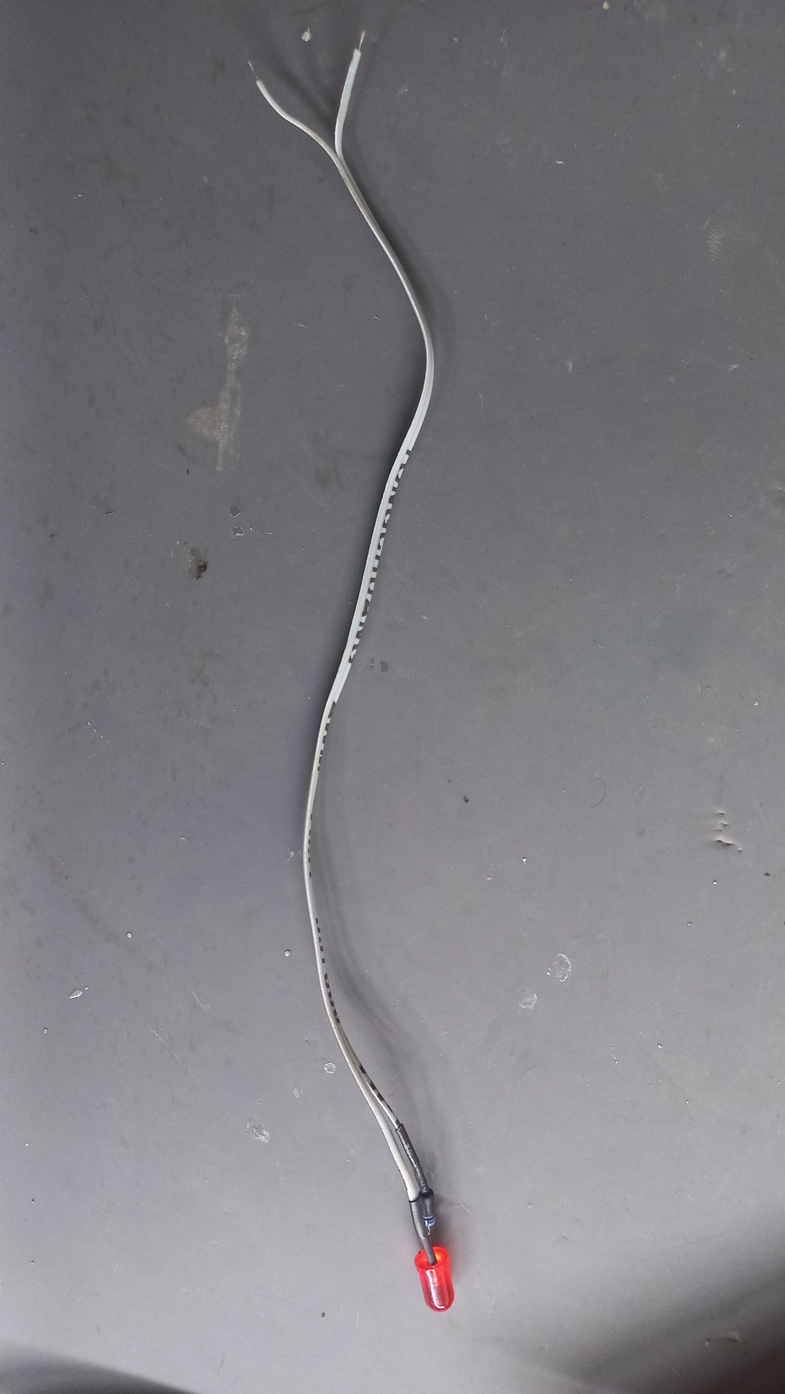
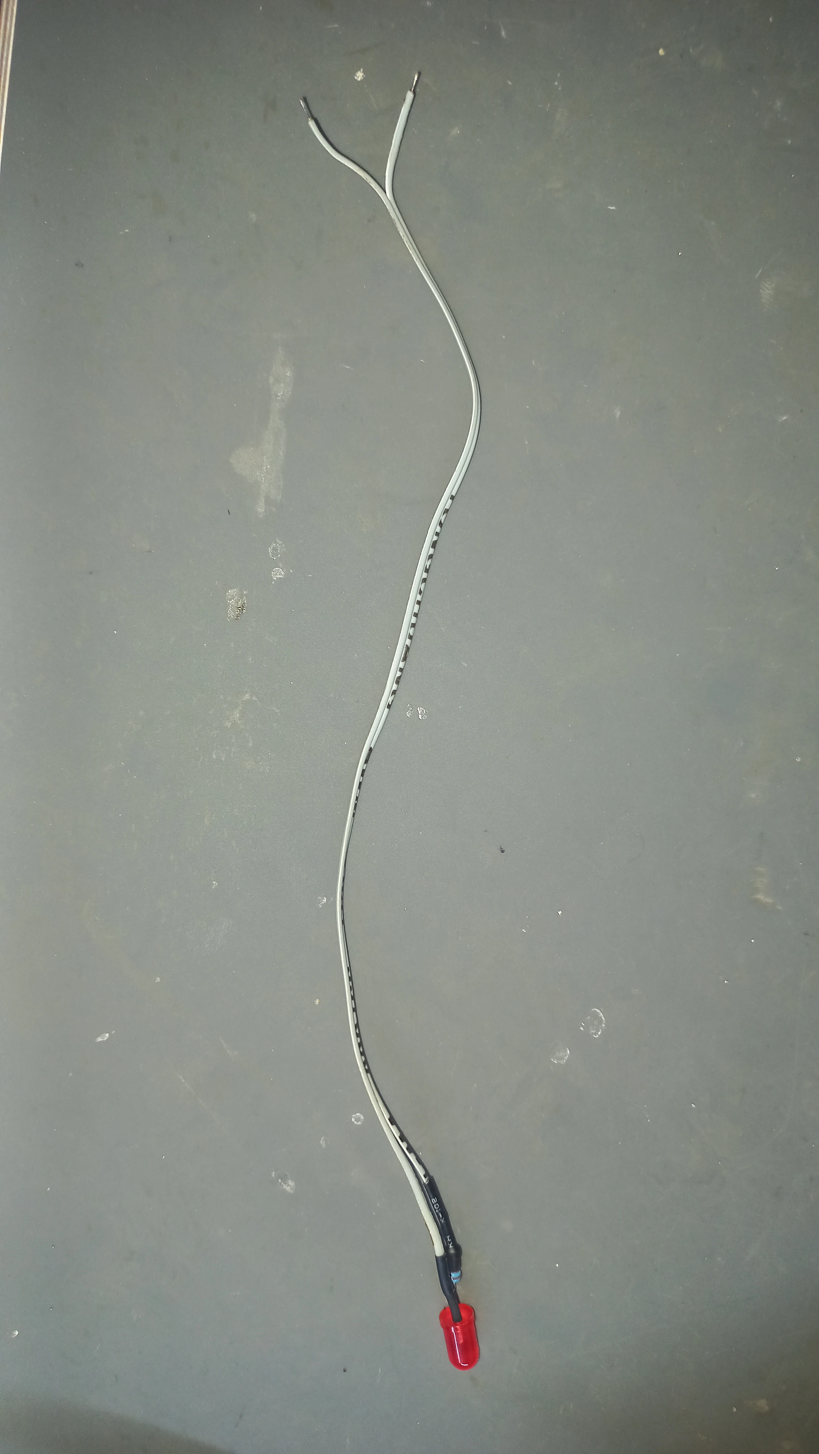
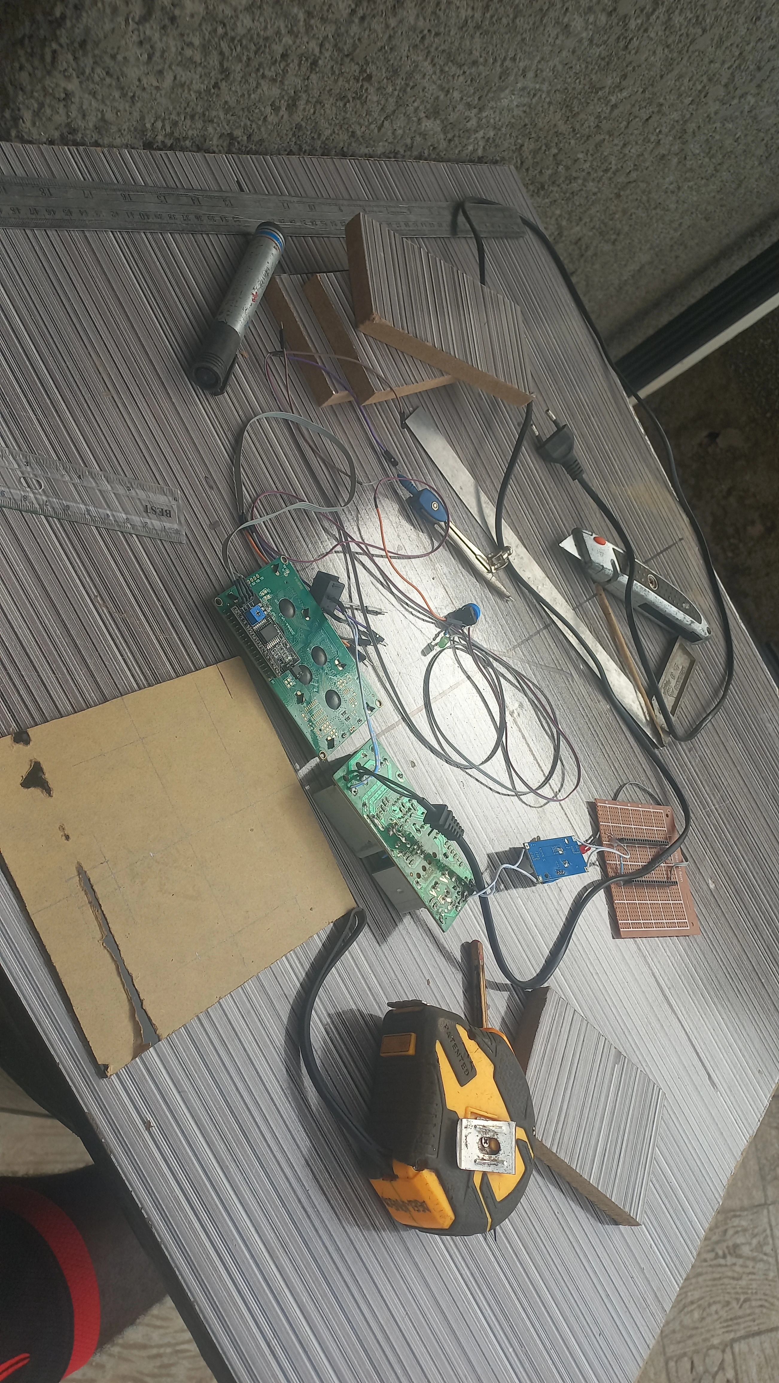
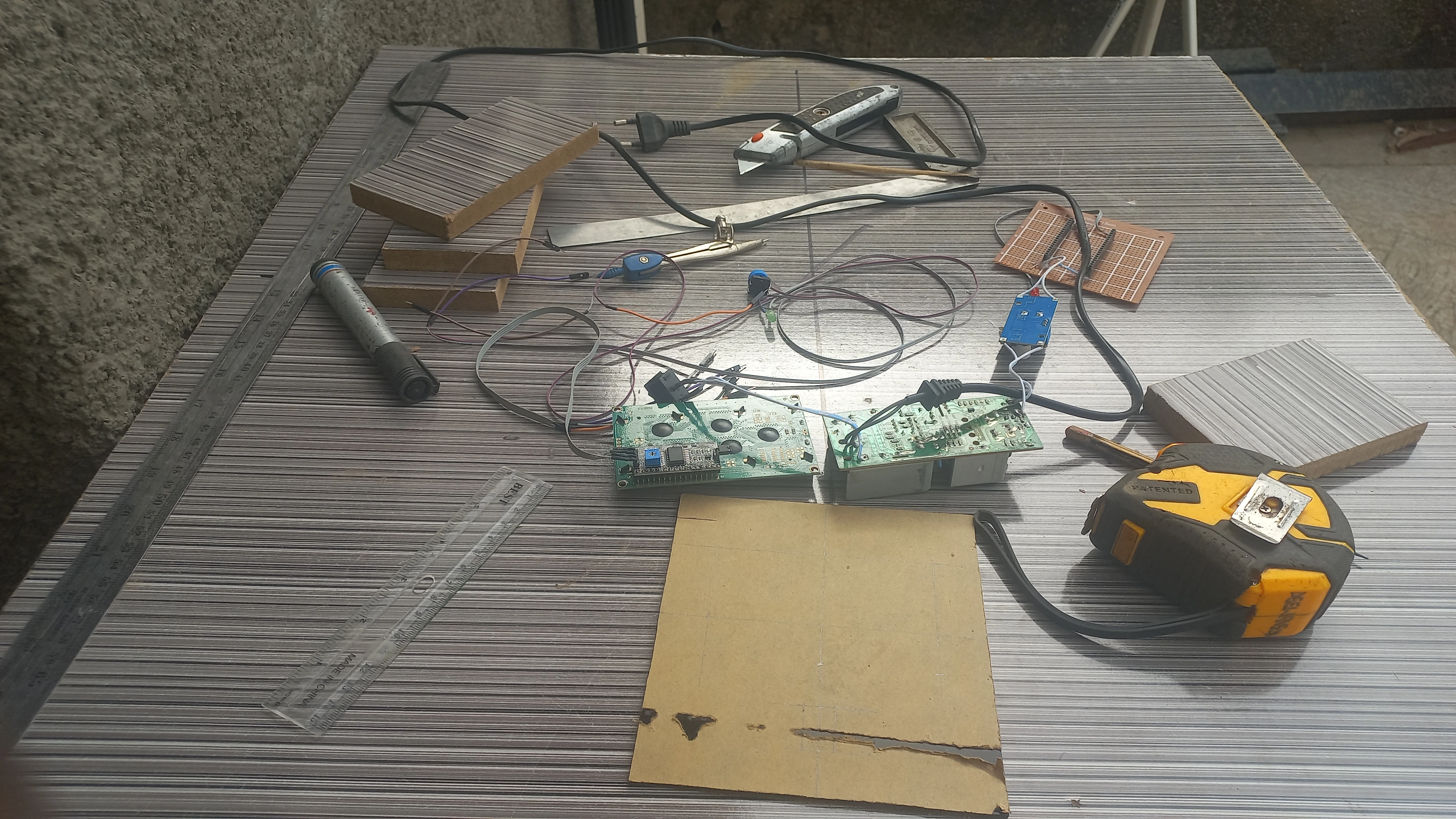
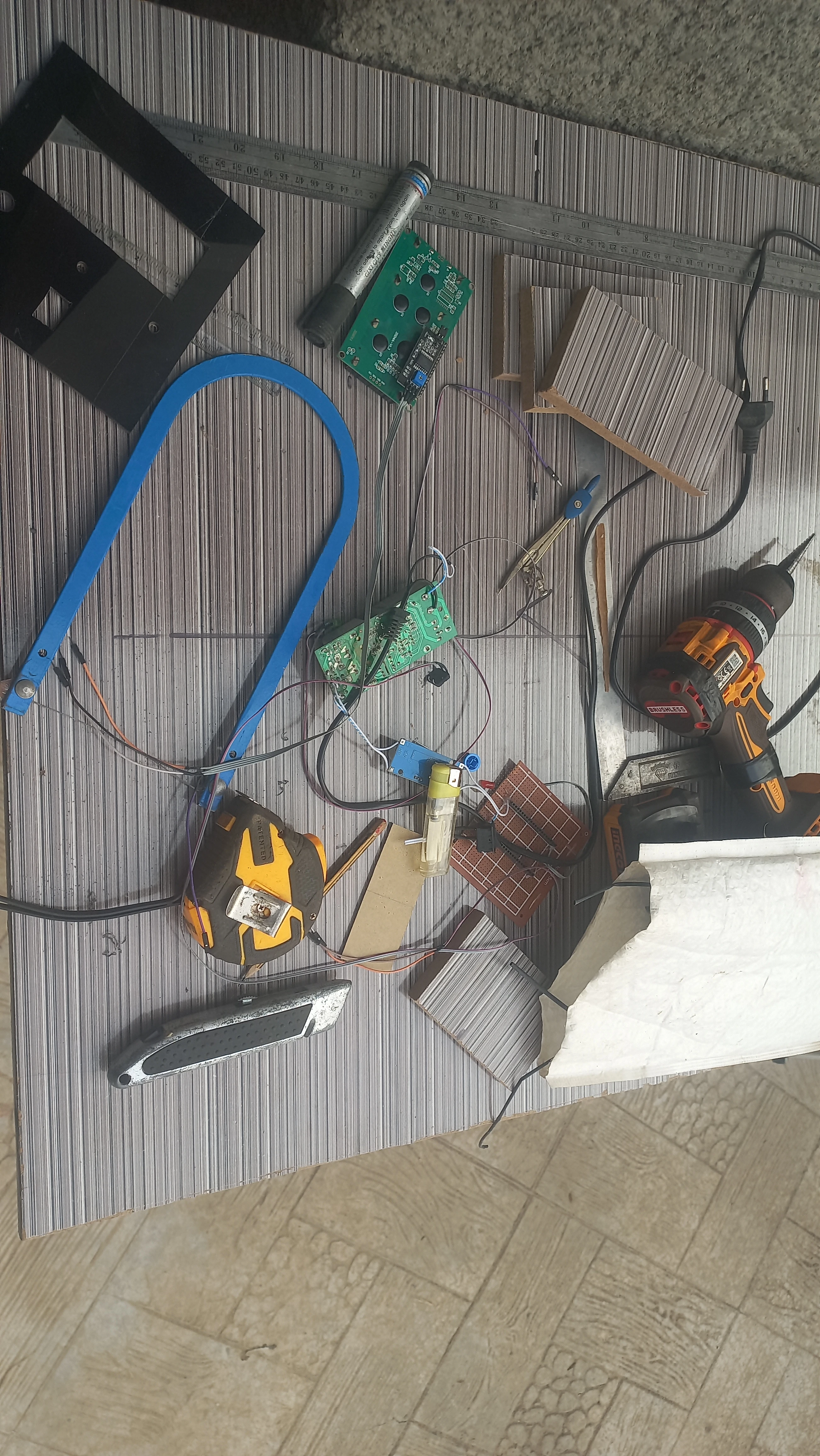
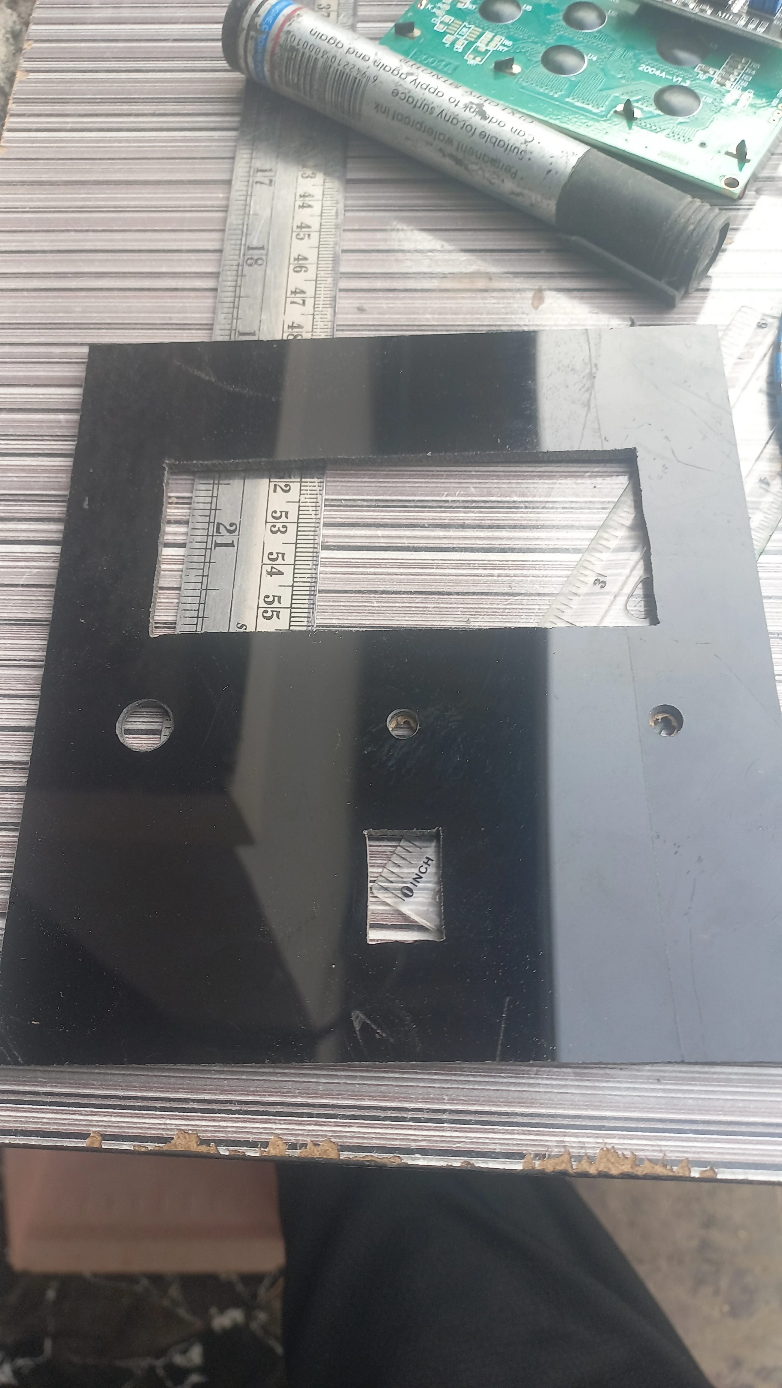
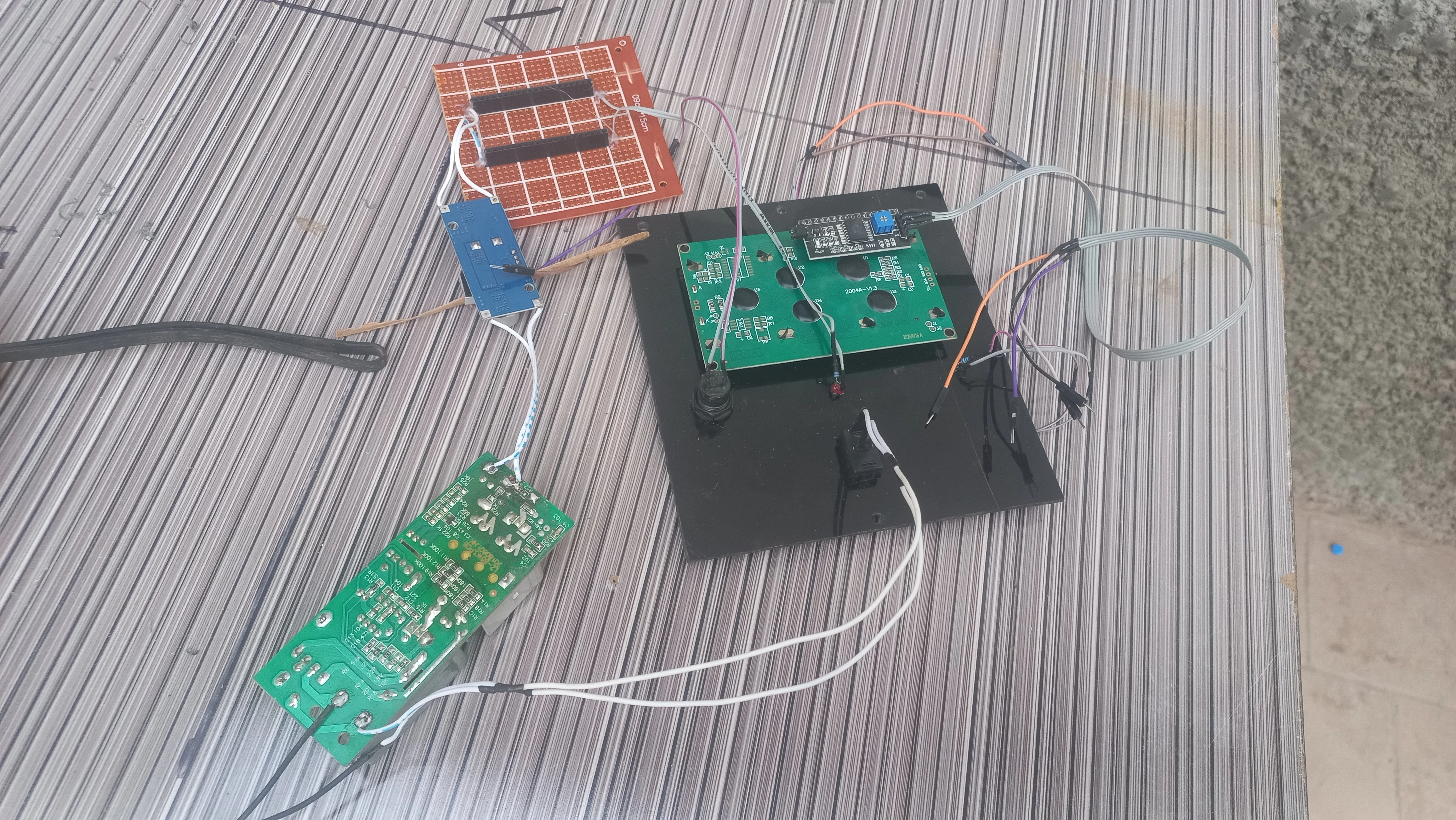
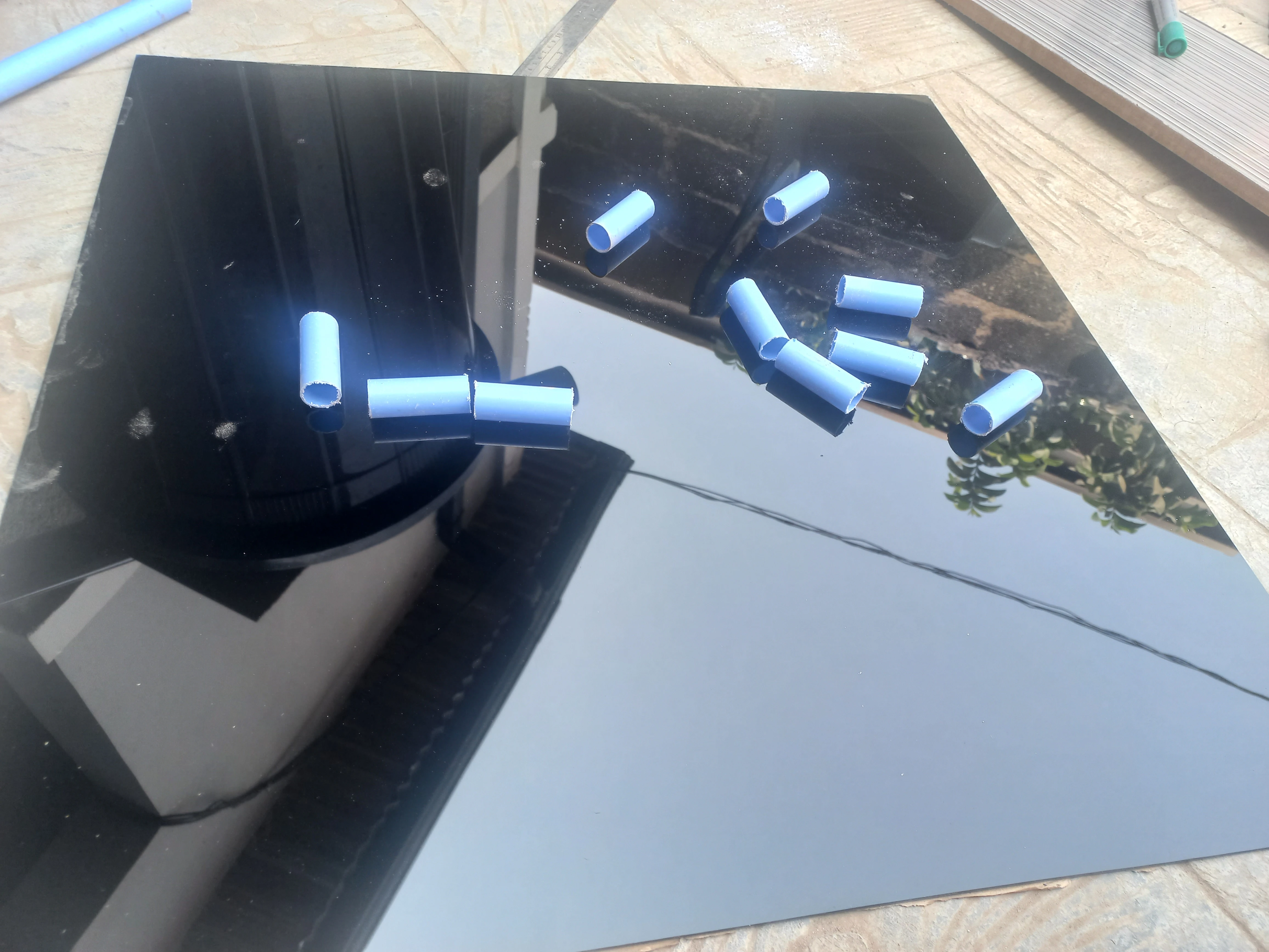
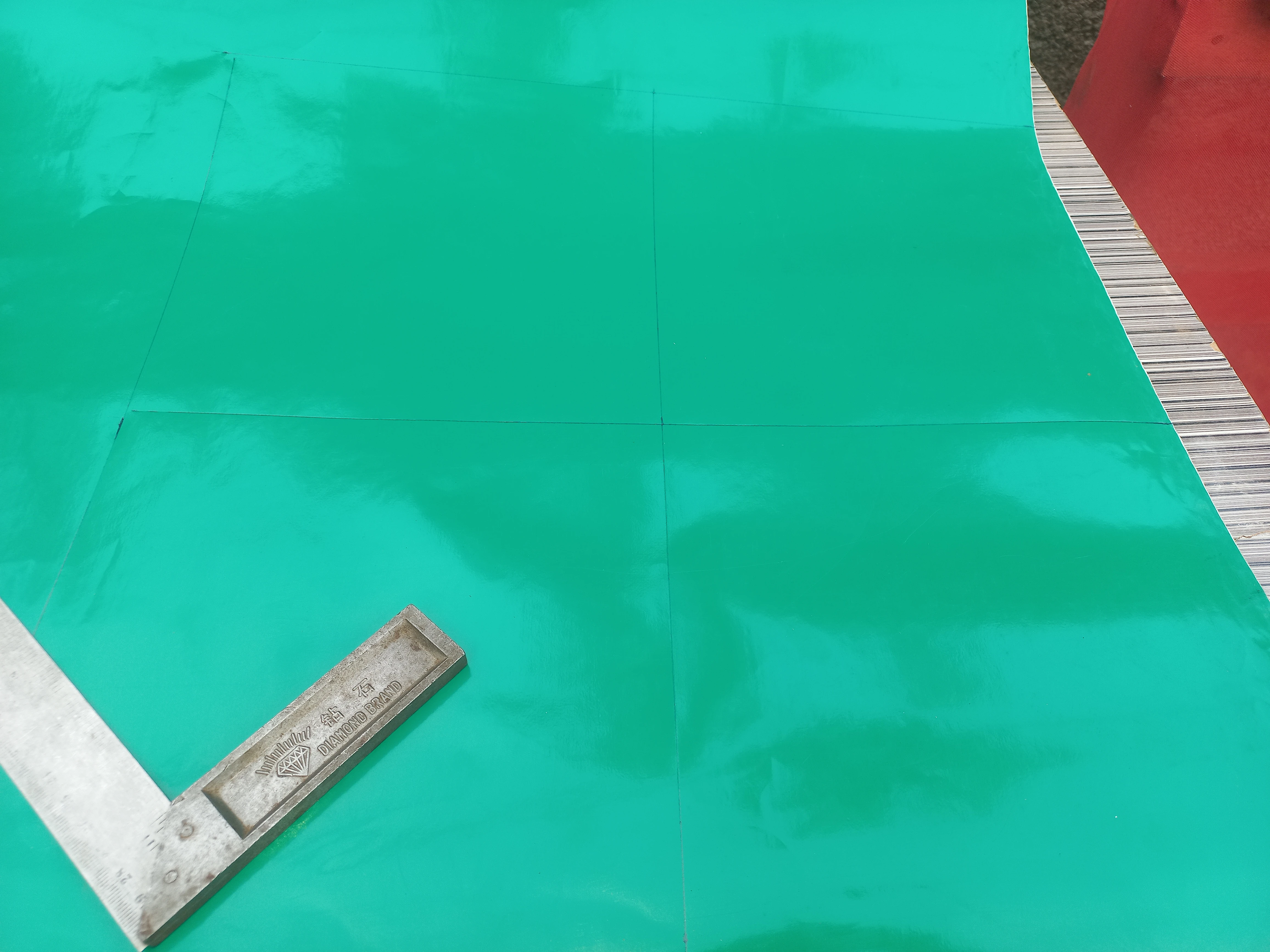
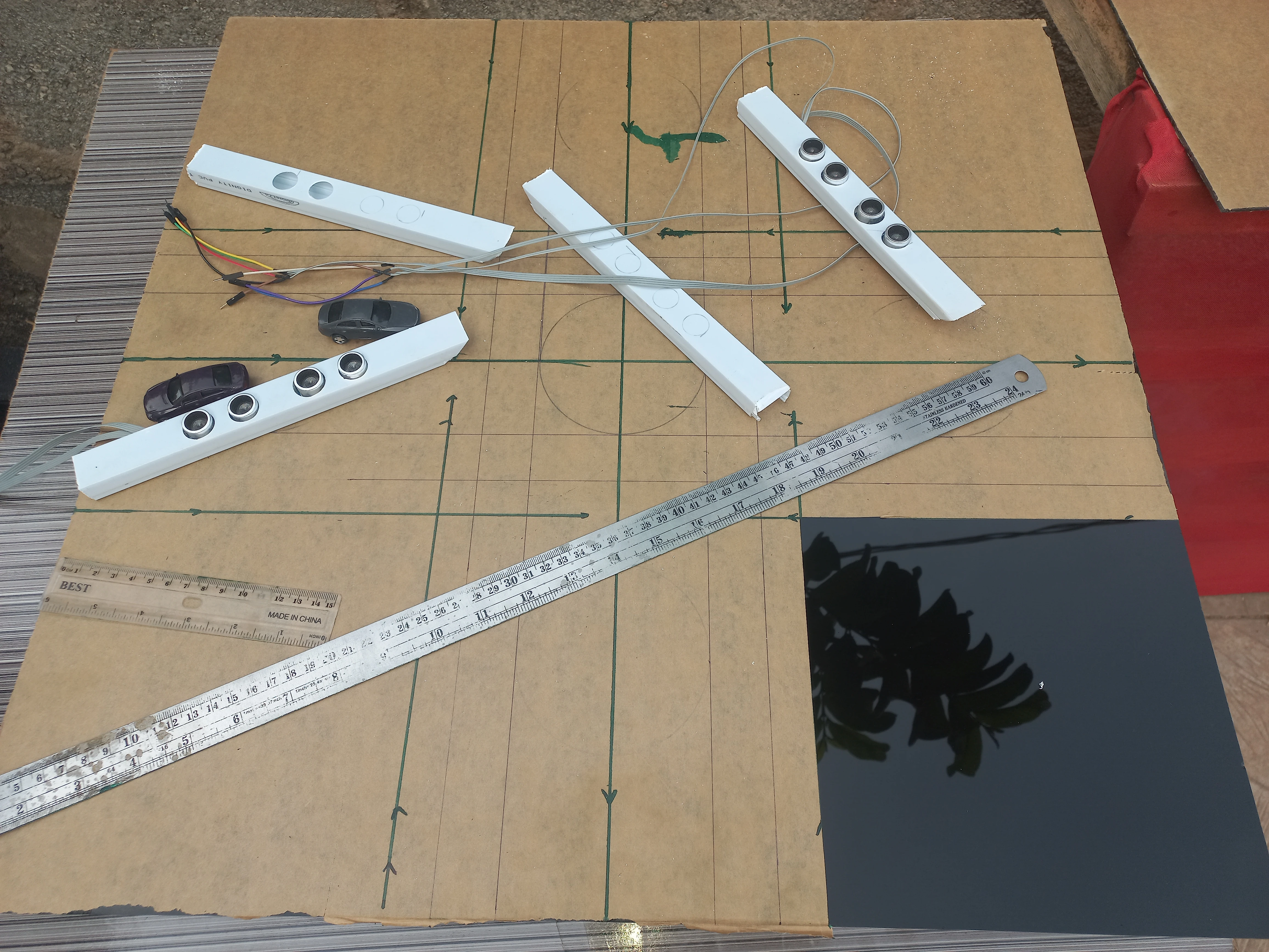
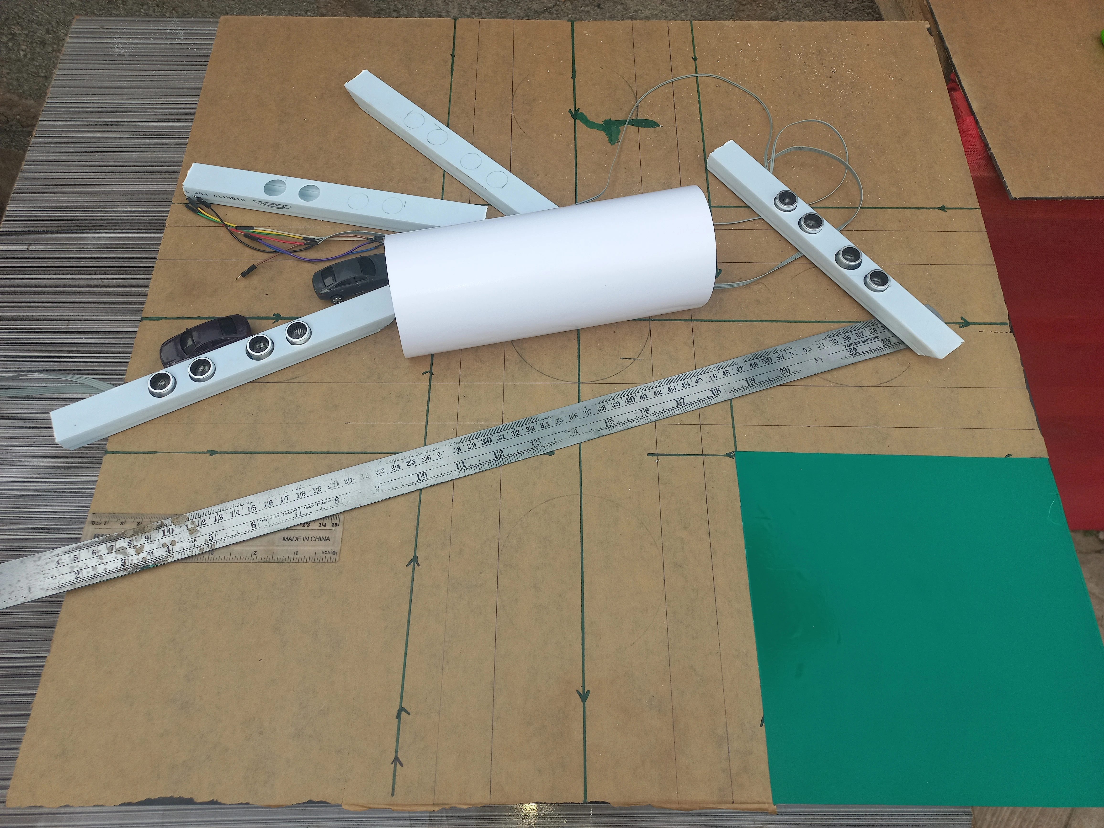
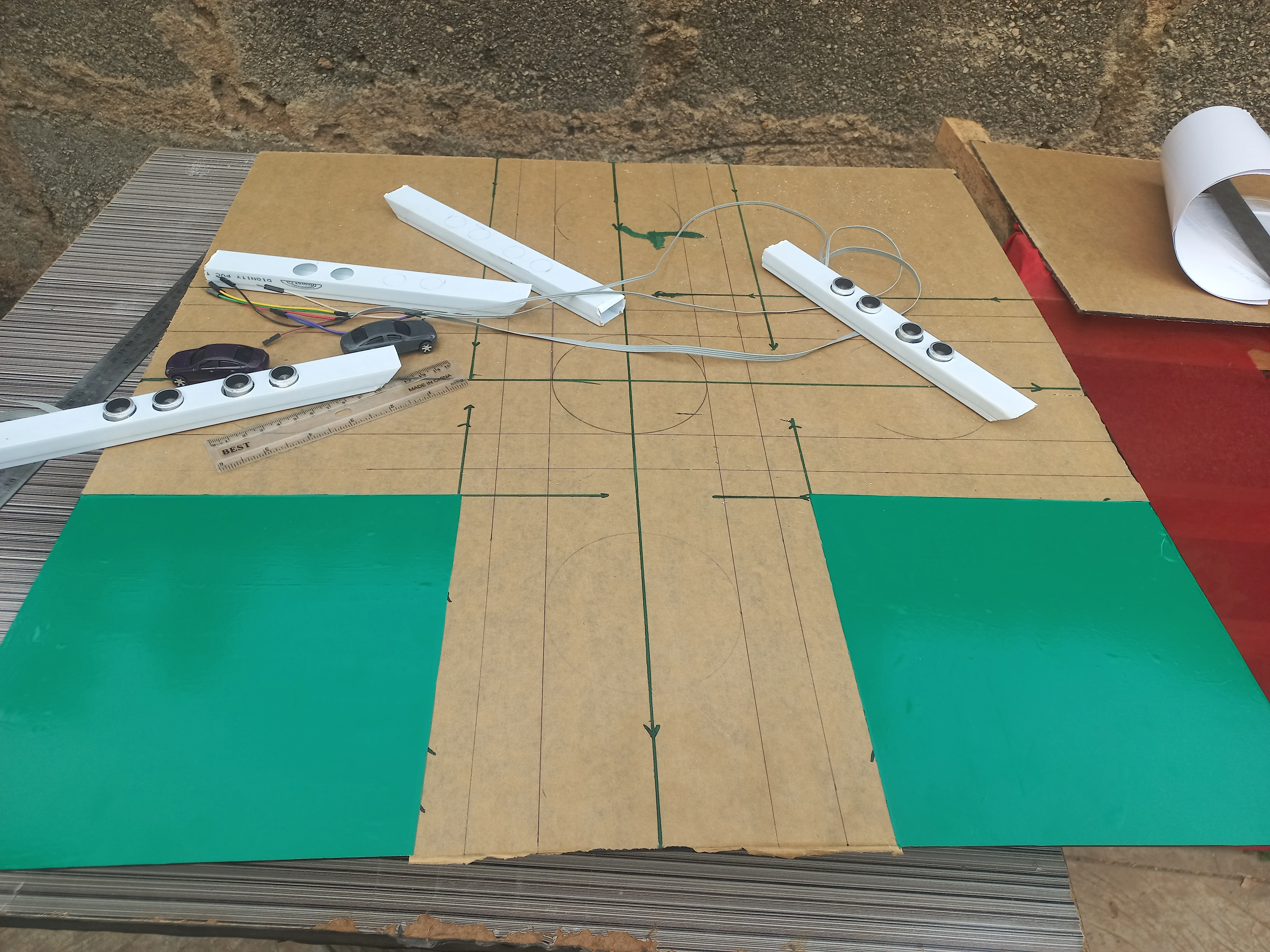
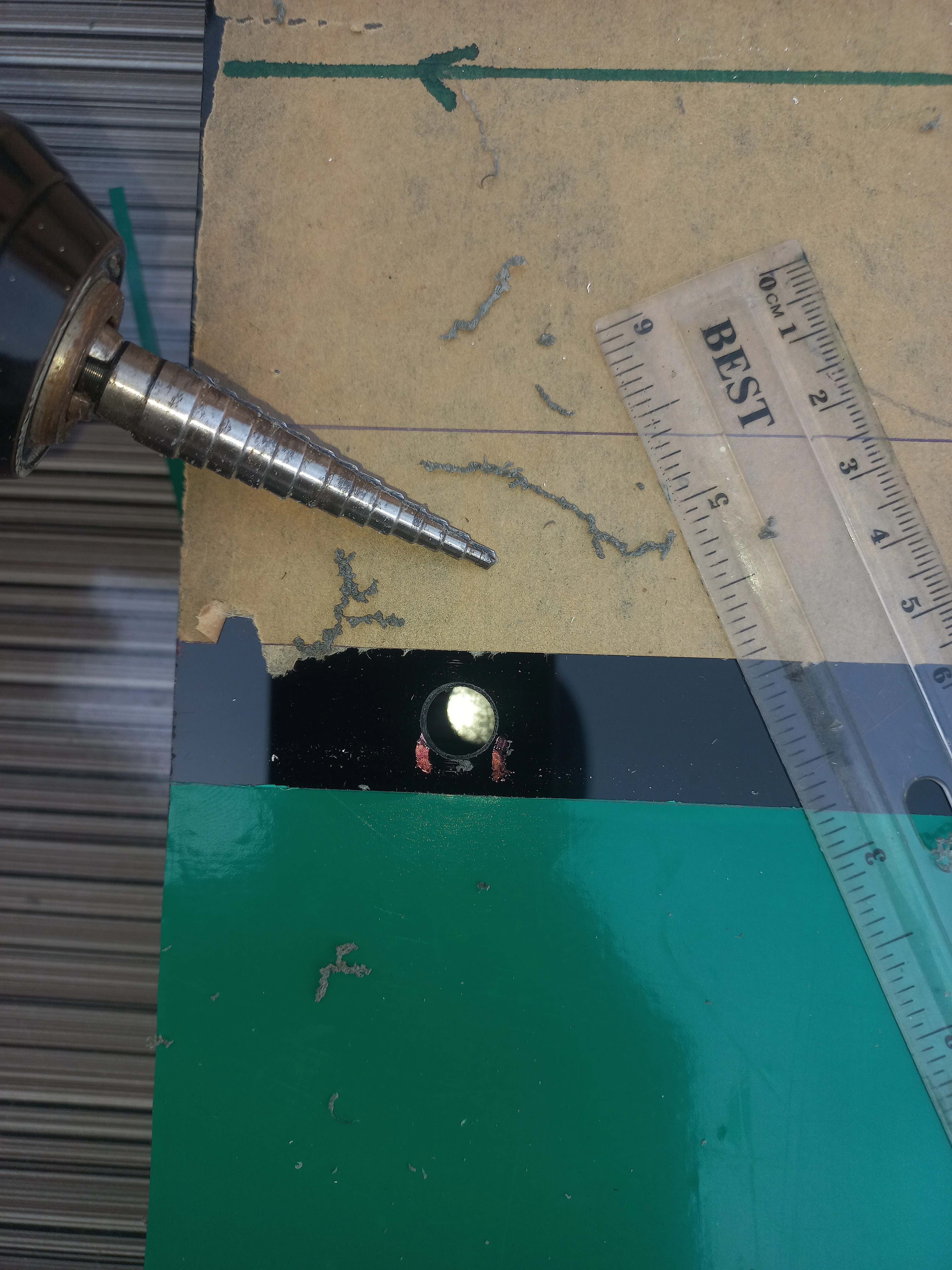
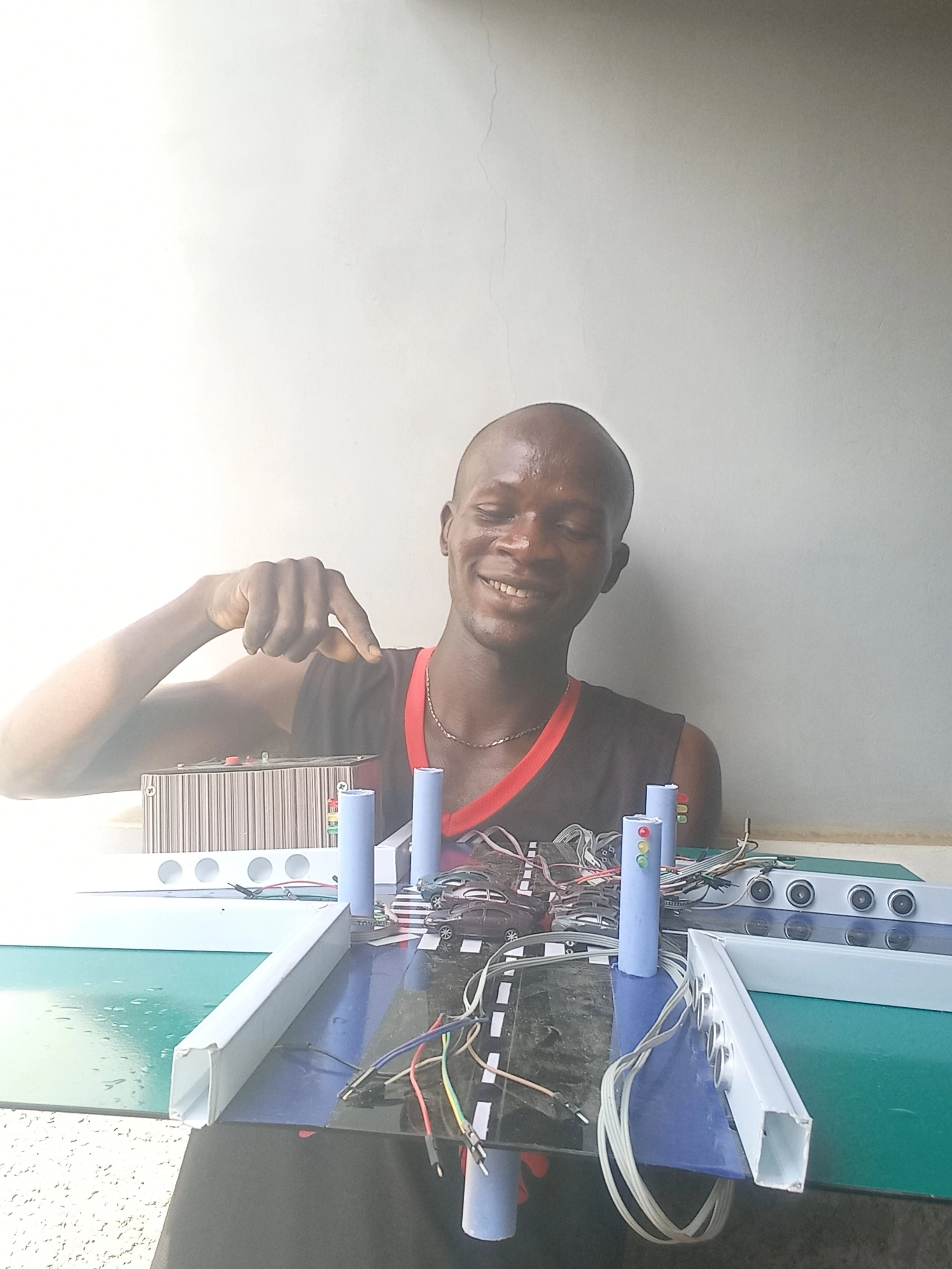
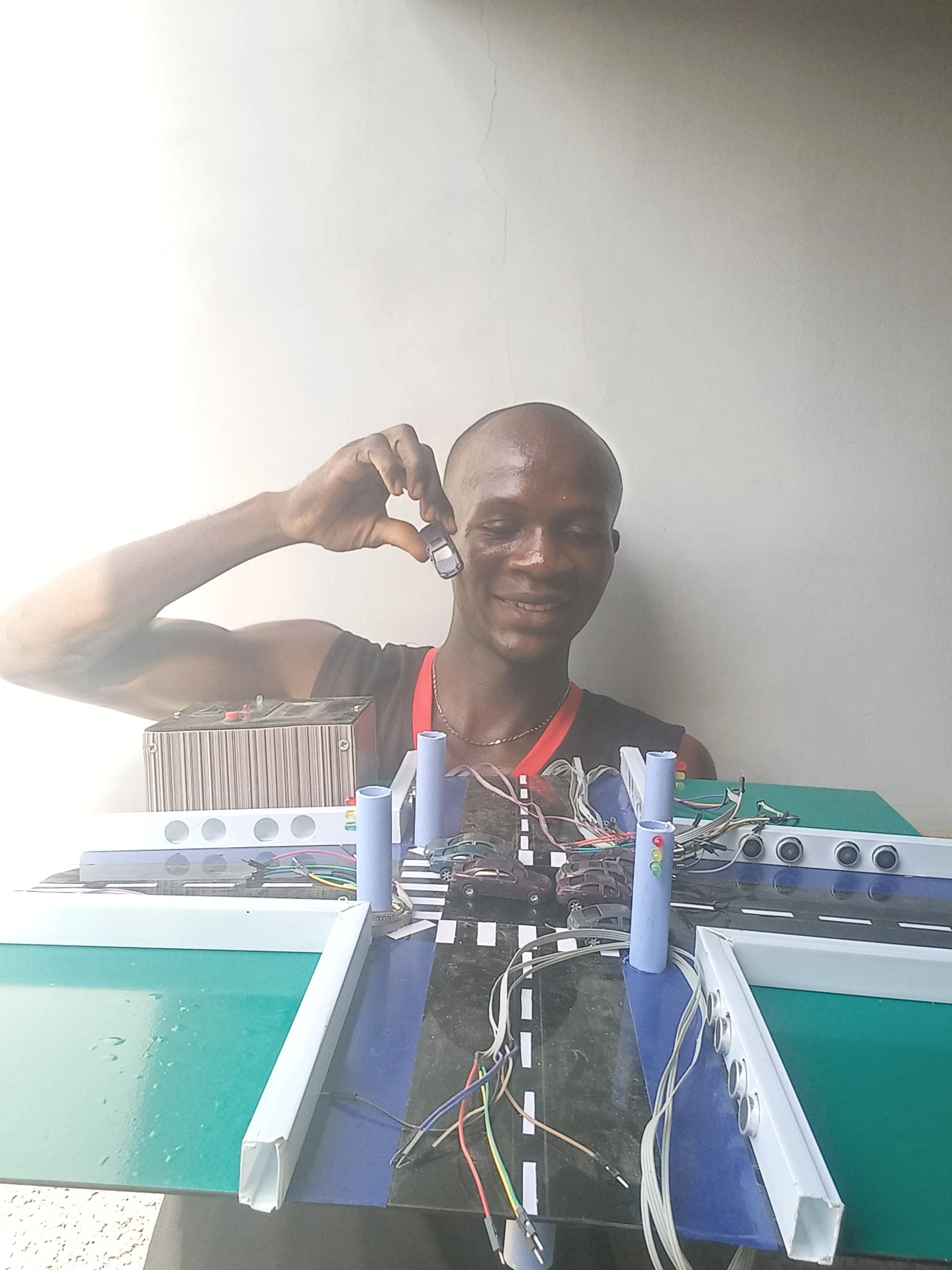
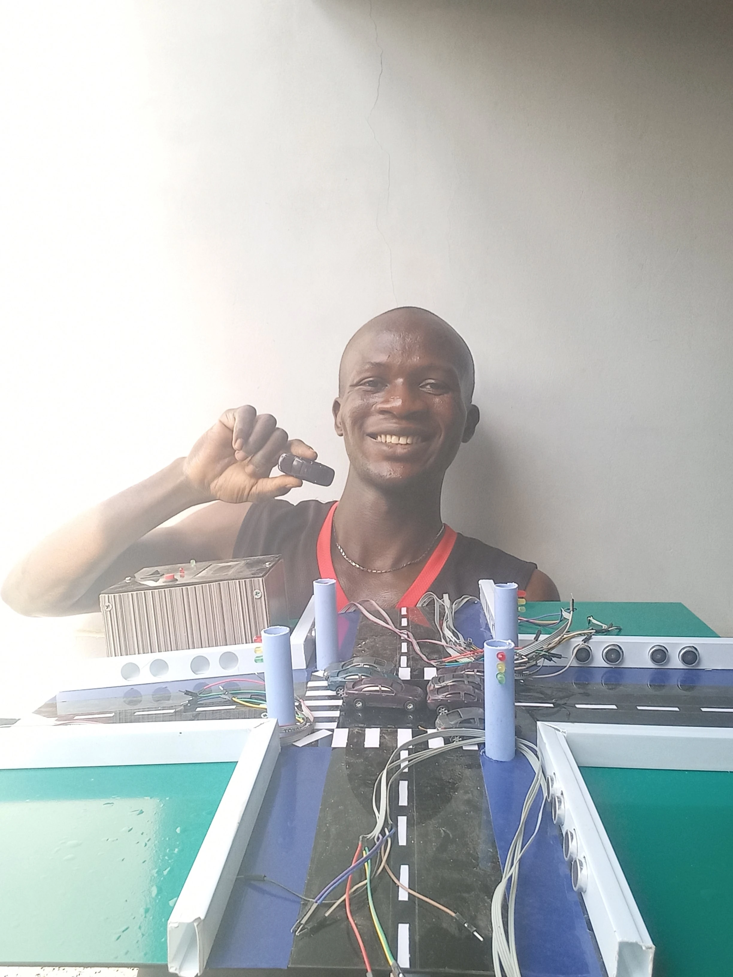
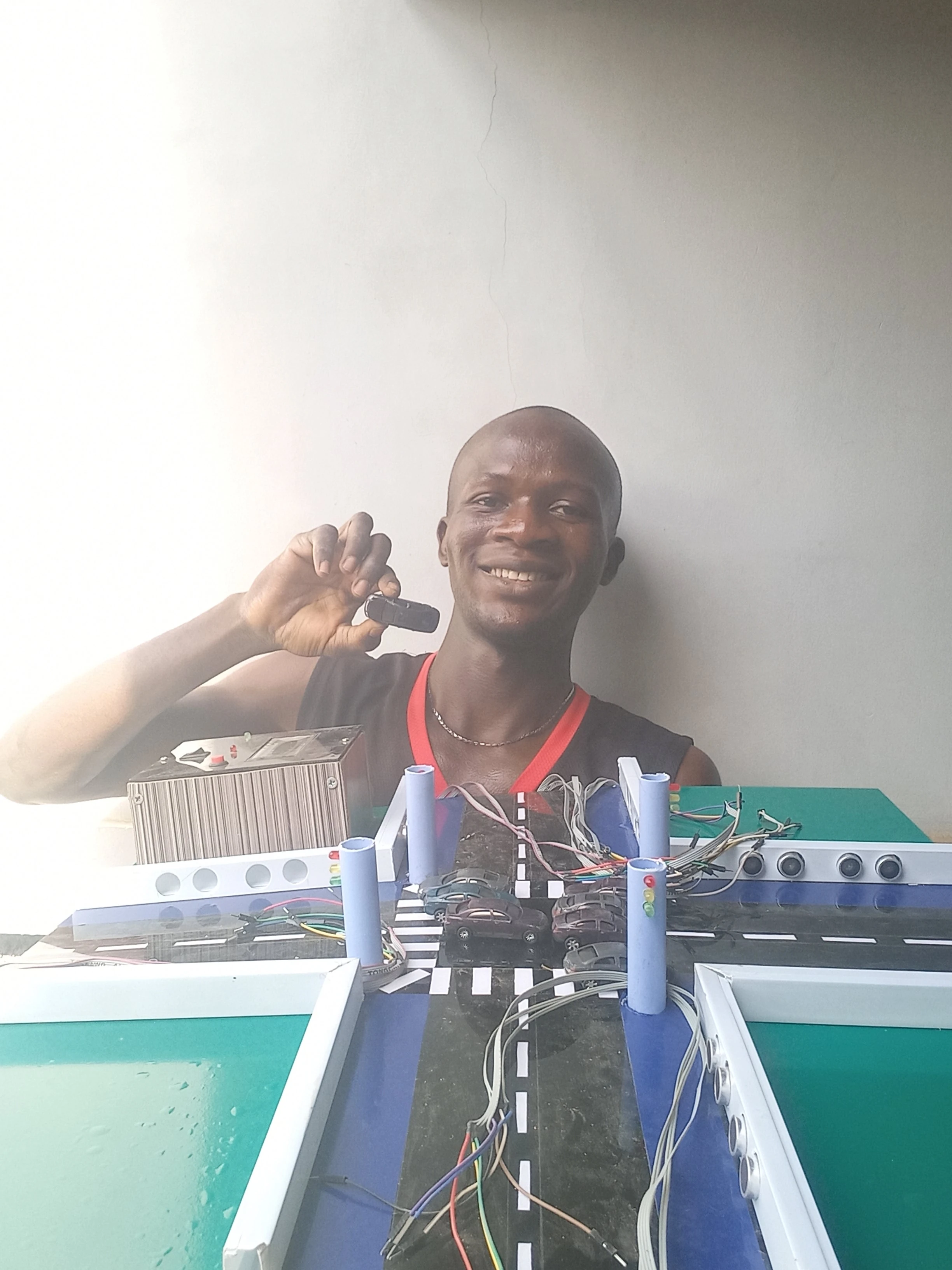
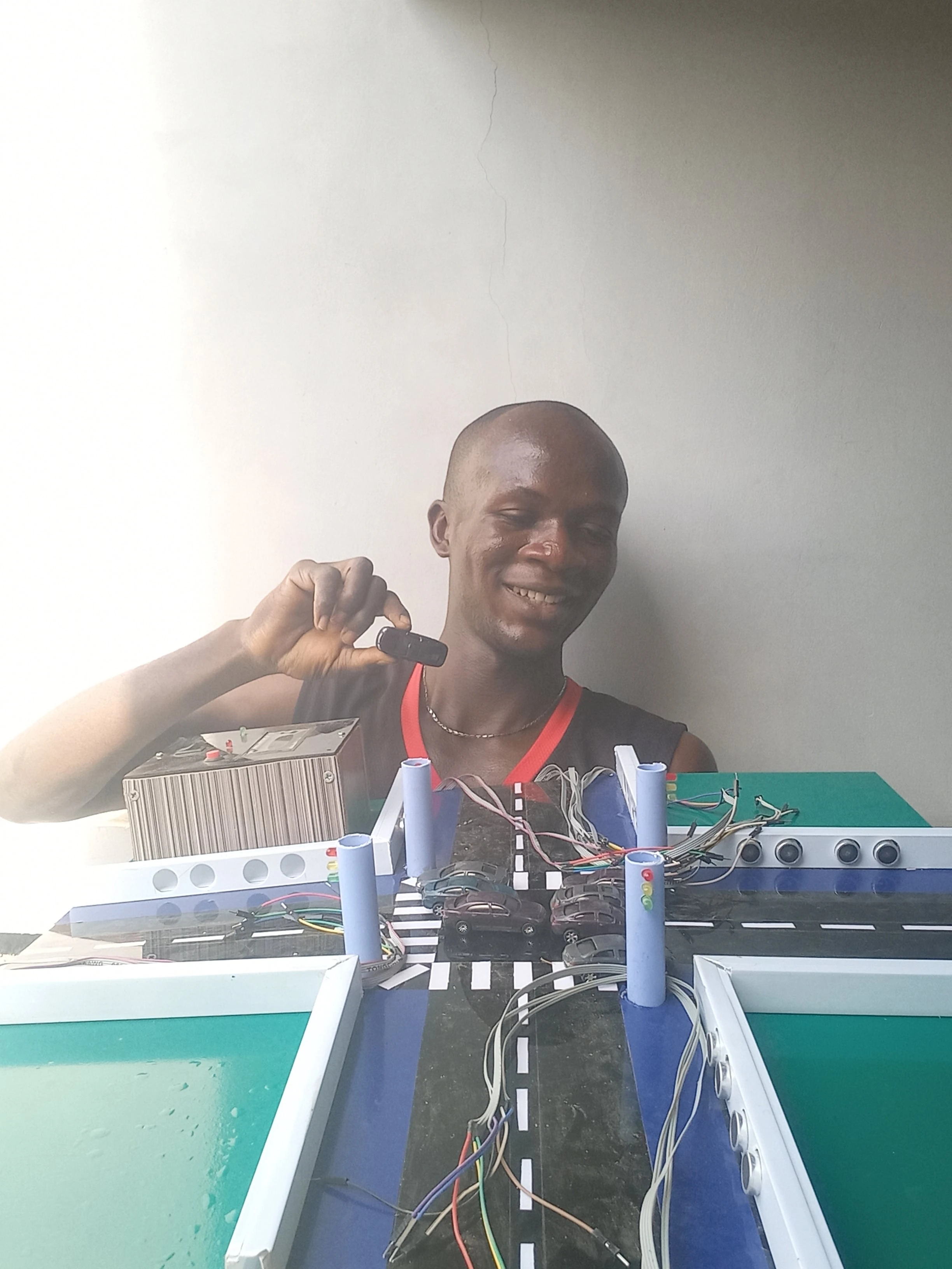
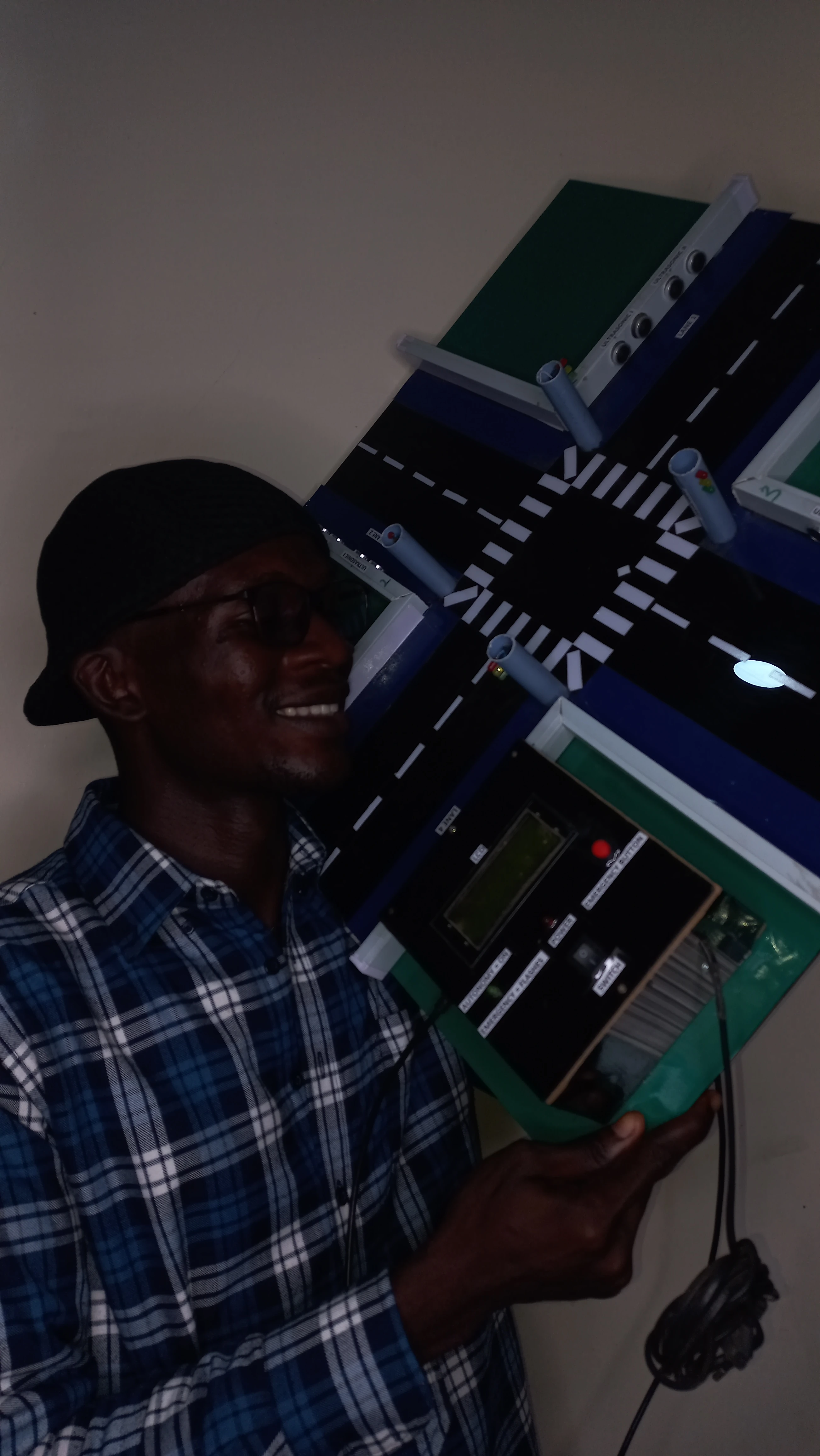
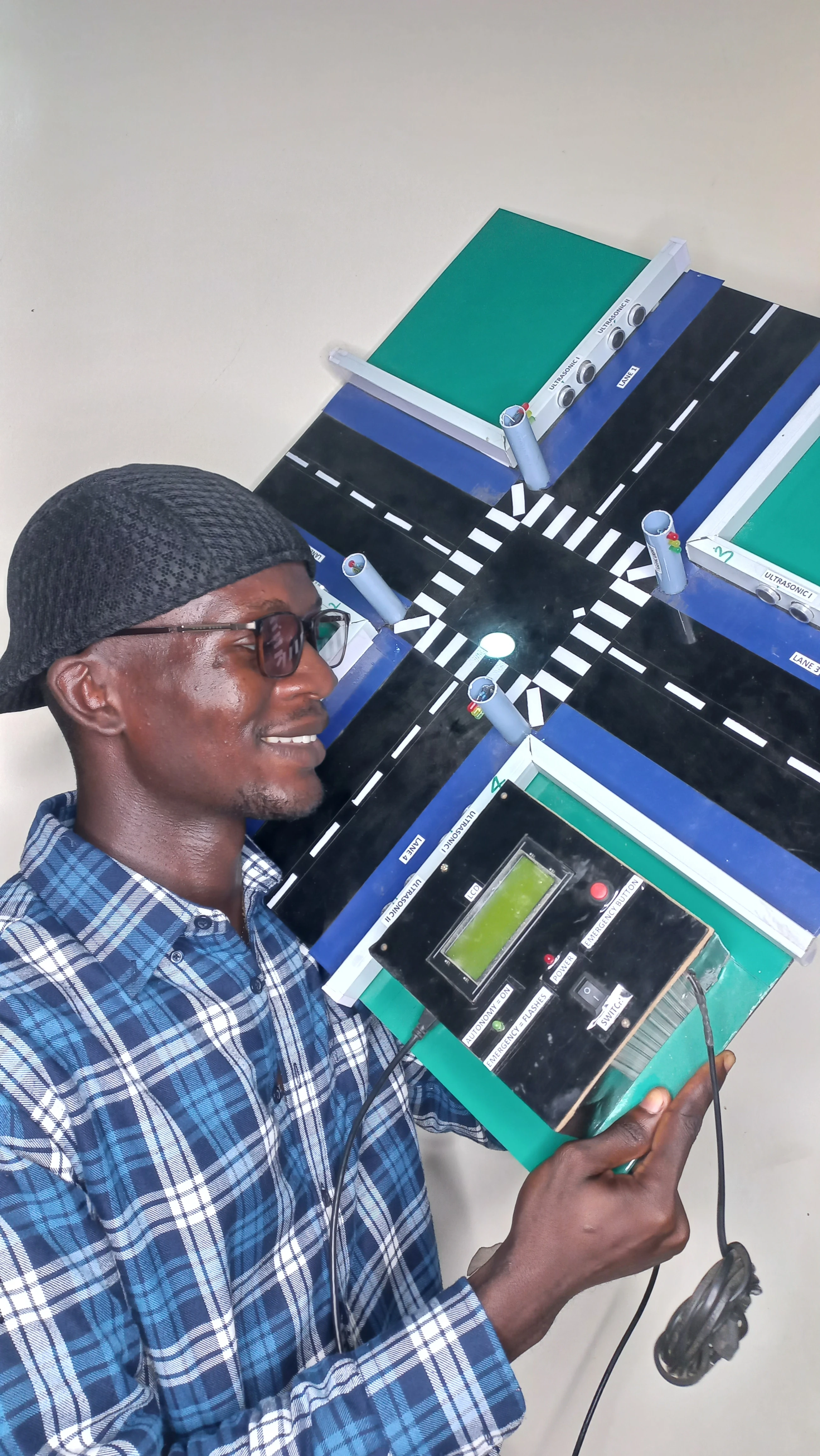
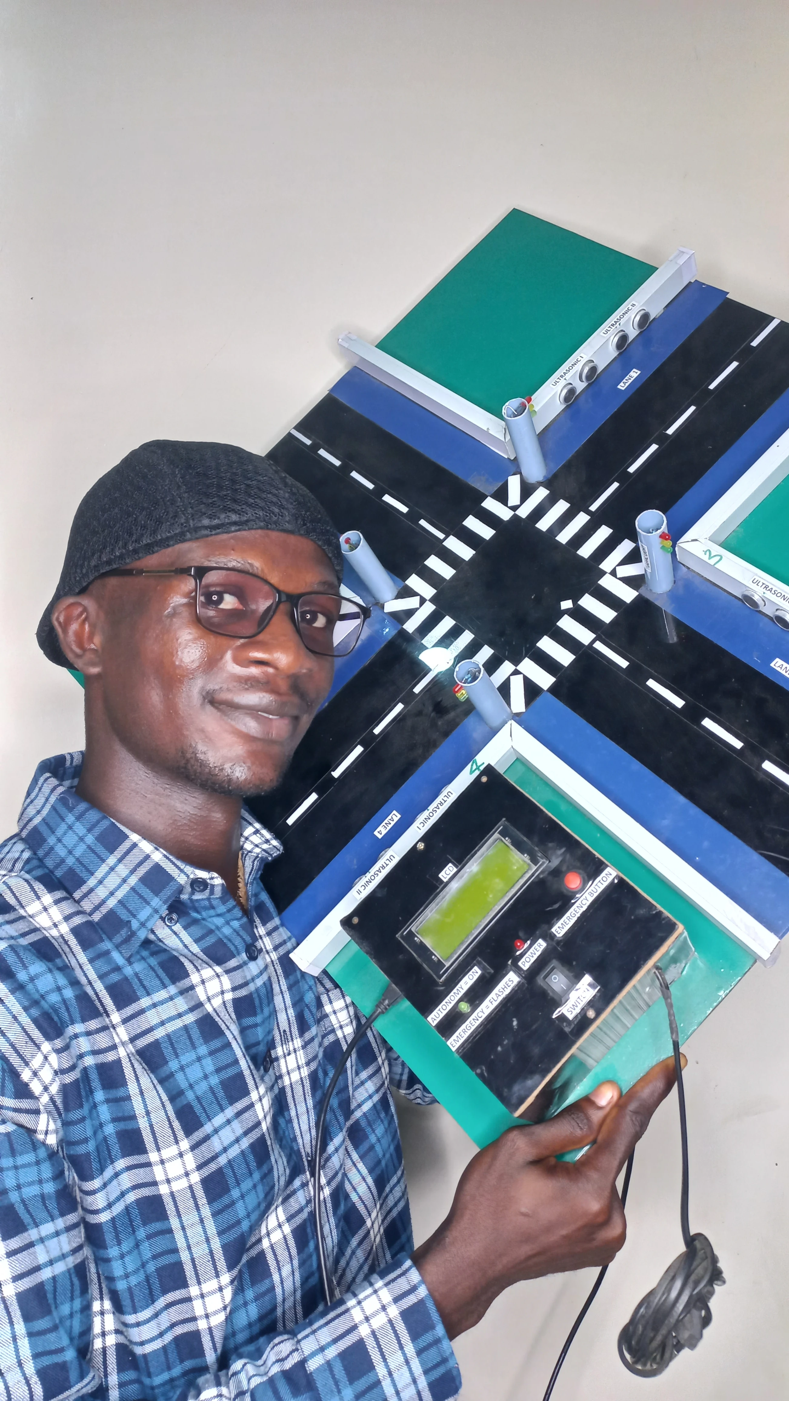
}134 photographs documenting the complete build process from initial component procurement through to final system presentation.


I sincerely appreciate you taking the time to explore my portfolio and learn about my work and expertise. If you have any questions or wish to discuss potential collaborations, please feel free to reach out via the Contact section.
Best regards,
Damilare Lekan, Adekeye.